This electronic clock, built on the Atmega8 microcontroller, is equipped with an easy-to-read LED display, an alarm clock with a snooze function, and a function to restore work after a power outage.
Watch characteristics
- time display format: hours, minutes;
- alarm clock with snooze function;
- simple control with 2 buttons;
- support for battery operation;
- supply voltage: 7 ... 12V / 0.2 A;
- dimensions of two printed circuit boards: 60 × 21 mm, 58 × 44 mm.
The schematic diagram of the clock is shown in the figure below. The clock circuit must be powered with a constant voltage in the range of 7 ... 12V. It can be anyone with a current load of at least 200 mA.
A buzzer with a generator can be connected to the CON5 connector of the board, which will act as an alarm sound. Buttons are connected to terminals SA1 and SA2 of the printed circuit board, which are used to enter settings and operate the clock.

Setting the time and alarm
When you press the SA1 button, we get to the “Set1” clock menu, where we have the ability to set the current time, and another short press of the SA1 button takes us to the “Set2” alarm clock setting menu.
To select and change settings, use the SA2 button. After selecting both in the time setting mode, as in the alarm clock setting mode, the first digit will flash on the display, after which you can set tens of hours using the SA2 button.
Pressing SA1 again will cause the second digit to flash and using SA2 you can set the units of hours. The next two presses of SA1 will set tens of minutes and units of minutes. When setting the hours and minutes, only one digit is always set. The fifth press of SA1 returns the watch to normal operation. Also, a long time without pressing the buttons completes the installation procedures.
While the watch is running, long pressing of the SA2 button turns on / off the alarm clock. When the alarm is activated, the time it starts is displayed for a few seconds. The state of the alarm clock is signaled by a dot located in the fourth digit. If the alarm is active, this indicator is on.
After turning on the alarm clock by pressing any button, you can turn it off for about 5 minutes, while the snooze function is activated. This fact is indicated by the blinking of a dot on the fourth digit of the indicator. After 5 minutes, the alarm will start again. By pressing any button again, it can be postponed for another 5 minutes, etc.
A complete shutdown of the alarm clock occurs after a long press of the SA2 key, or about a minute and a half without a response from the user.
The watch is tested in Proteus:

If, during the operation of the watch, it turns out that the watch is significantly behind or in a hurry, you can try to decrease or increase the value of the capacitor C1.
(34.7 Kb, downloaded: 1 652)
In the photo there is a prototype that I assembled to debug the program that will manage this entire economy. The second arduino nano in the upper right corner of the breadboard does not belong to the project and sticks out there just like that, you can ignore it. 
A little about the principle of operation: Arduino takes data from the DS323 timer, processes them, determines the level of illumination using a photoresistor, then sends everything to the MAX7219, and it, in turn, lights the necessary segments with the desired brightness. Also, using three buttons, you can set the year, month, day, and time at will. In the photo, the indicators display the time and temperature, which is taken from a digital temperature sensor.
The main difficulty in my case is that 2.7 inch indicators with a common anode, and they had to be first somehow made friends with the max7219, which is sharpened for indicators with a common cathode, and secondly, to solve the problem with their power supply, since they need 7.2 volts for glow, which the max7219 alone cannot provide. After asking for help on one forum, I got the same answer.
Screenshot solution: 
A microcircuit clings to the outputs of the segments from max7219, which inverts the signal, and a circuit of three transistors clings to each output, which must be connected to the common cathode of the display, which also invert its signal and increase the voltage. Thus, we get the opportunity to connect displays with a common anode and a supply voltage of more than 5 volts to the max7219.
For the test, I connected one indicator, everything works, nothing smokes 
We begin to collect.
I decided to divide the circuit into 2 parts because of the huge number of jumpers in the version that was divorced by my crooked legs, where everything was on one board. The clock will consist of a display unit and a power and control unit. It was decided to assemble the latter first. Aesthetes and seasoned radio amateurs, please do not faint because of the abuse of parts. There is no desire to buy a printer for the sake of LUT, so I do it the old fashioned way - I train on a piece of paper, drill holes according to a template, draw a track with a marker, then bait.The principle of fixing the indicators is the same as on.
We mark the position of indicators and components using a plexiglass template made for convenience.
The markup process


Then, using the template, we drill holes in the right places and try on all the components. Everything fell flawlessly.

We draw paths and we poison. 

bathing in ferric chloride 
Ready!
control board: 
indication board: 
The control board turned out to be excellent, the track on the display board did not critically gobble up the track, this is fixable, it's time to solder. This time I lost my SMD virginity, and included 0805 components in the circuit. At the very least, the first resistors and capacitors were soldered in place. I think I'll fill my hand further, it will be easier.
For soldering, I used the flux I bought. It is a pleasure to solder with it, now I use alcohol rosin only for tinning.
Here are the finished boards. The control board has a seat for an arduino nano, a clock, as well as outputs for connecting to a display board and sensors (photoresistor for auto brightness and a digital thermometer ds18s20) and a power supply unit with adjustable output voltage (for large seven-segment devices) and for powering the clock and arduino, the display board contains slots for displays, sockets for max2719 and uln2003a, a solution for powering four large seven-segment devices and a bunch of jumpers.


rear control board 
Rear display board: 
Horrible installation smd: 
Running
After soldering all the cables, buttons and sensors, it's time to turn it on. The first launch revealed several problems. The last big indicator was off, and the rest were dim. I dealt with the first problem by soldering the leg of the SMD transistor, with the second - by adjusting the voltage issued by the lm317.IT'S ALIVE!

A variant of the implementation of a large LED clock
We will talk about LED watches, assembled on large seven-segment displays 70X110 mm with a common cathode, having 6 LEDs per segment and, accordingly, requiring a clock power supply of just over 12 volts. The maximum current consumption of the segment is 30 mA, but in our design the segment consumes about 13 mA, which is more than enough for normal visibility. Also, the watch has a thermometer on the DS18B20 sensor and a stroke correction. Controller - Atmega8. When the power is turned off, the watch runs on three AA batteries, while the indication turns off.
The ready-made firmware and circuit of the respected Alexander was taken, the original article can be found.
The circuit was redone for these indicators, that is, keys on bipolar transistors in the anode circuits and a ULN2003 microcircuit in the cathode circuits were added.
Resistors R43-R49 and R50-R53 are not really needed, they are installed here so that Proteus adequately triggers the circuit. The circuit could be simpler if we used field-effect transistors and indicators with a common anode.
The design uses transistors BC847 and BC857. Resistors in 20 Ohm anode circuits, and you do not need to select them, since it is enough to select the supply voltage that comes with the LM317. In my case, it is 12.7 volts. D2 is a point, in indicators it is usually one LED. It only needs to be connected to one indicator.
The setting is done by pressing the SET button, in a circle.
1. Minutes and seconds display mode. If in this mode you simultaneously press the button PLUS and MINUS, then the seconds will be reset.
2. Setting the minutes of the current time.
3. Setting the current time clock.
4. The value of the daily correction of the clock rate accuracy. Symbol c and correction value. Setting limits -25 ÷ 25 sec. The selected value will be daily at 0 hours 0 minutes and 30 seconds added / subtracted from the current time.
5. Symbol t. Setting the clock display duration.
6. Symbol o. setting the time for displaying the temperature from the internal sensor.
7. Symbol P. setting the display time of the advertising splash screen.
Setting limits for display time 0 ÷ 60 sec. If 0 is set, this parameter is not displayed on the indicator. If all parameters are set to 0, the indicator will display hours.
In all modes, holding the buttons PLUS / MINUS an expedited installation is performed.
If changes were made to the settings, 10 seconds after the last change, the new values will be written to the non-volatile memory (EEPROM) and will be read from there when the power is turned on again. The indicator will switch to the main time mode.
The new settings take effect during installation.
The microcontroller monitors the presence of the main power supply. To reduce the current consumption when it disappears, the indicator, sensors and buttons are turned off. The clock continues to count down. When power is supplied from the main source, all functions are restored.
Microcontroller fuses:

Now directly about the implementation of the scheme. First, the board was collected.


The indicators were connected to each other with an MGTF wire, and with the board through connectors.
Indicators are held together by means of fiberglass strips screwed into them


Then I soldered the sensor to the board and started the circuit.

An electrical panel for 18 modules with a transparent cover was purchased as a case.

As you can see, indicators can be perfectly installed in the flap, all that remains is to cut out a window of the appropriate size.

After using a knife, pliers and a file to make a window, the indicators were installed inward and secured with staples cut from the strip for fastening the machines.


A battery compartment, a transformer and a power supply board are installed on the rear cover of the shield. A window for adjusting the clock is also cut out, since the buttons remain on the board. The parts are installed so that the center of gravity of the whole structure is in the middle, since the shield will hang on one self-tapping screw.
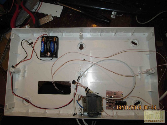
Running the finished clock. The tinted cover satisfactorily hides the screws, wires and white segments, while at the same time clearly showing the luminous segments through it.
Hello everyone! On the eve of the holiday on March 8, have you already figured out what to give? Not really? You can certainly buy a ready-made gift, but the best gift is a handmade gift. And so, I wondered: what to give Mom for March 8? I thought ... I thought ... Oh, I'll give you a watch. But I don’t want to buy a Chinese watch and I won’t be for two reasons: it will break right away, I’m a radio amateur. And I decided to make my own watch with my own hands! And here's what came of it:
Now I will tell you how to make such a watch myself, but about everything in order.
And so what did I want? And I wanted to make a clock big enough on LED seven-segment indicators so that it just showed the time and went even when they were turned off. The design was based on the Attiny2313 AVR microcontroller with two kilobytes of flash, this is more than enough. The clock itself was implemented using the RTC of the DS1307 real-time microcircuit, to which a 3-volt battery is connected to maintain the clock. Seven-segment indicators were supplied by REC-S12101AG, green, with a common anode. Their dimensions are 28.8 x 40.8 mm. Since the clock needs 5 volts to power it, I used a ready-made switching power supply RS-25-5. Why such a UPS? It lay in my box with the details (a long time ago, a year ago I bought it for five thousand Belarusian rubles from one guy, I think a good UPS will come in handy!), Gathering dust, and I did not have a transformer, so I put what was. With the power supply unit, the watch is powered from a 220 volt mains voltage. Here is a photo of the UPS:

Well, in fact, there should be no difficulties in assembling the watch. And so, the schematic diagram of the clock:


I assembled everything on printed circuit boards, placed the seven-segment indicators on one board, everything else on the other. The boards were tinned with rose alloy and covered at the end. I made printed circuit boards using. I drew in the program. Here is a photo of the board with seven-segment LEDs:


I connected the boards together with a loop, like this:

A computer IDE loop can be used. Here is a photo of the main board:


Please note that the case of the watch quartz must be connected to the minus of the power supply, this allows you to avoid malfunctions and external interference. I put everything in the case, this is what happened:


As you can see, inside the case, I secured everything with thermal glue. After assembling the clock, you need to flash the microcontroller with the ClockFirmware.HEX firmware. How to flash a microcontroller and make a programmer, I wrote and. Don't forget to install the following fuse bits after flashing:


I was flashing the microcontroller using the programmer and the SinaProg program. I wrote the program (firmware) for the clock in the environment, the source code is attached. My clock has been running for almost a week and is not lagging behind for a second. The accuracy of the watch depends on the quartz, it is better to buy a new one. The brightness of the clock depends on the resistors R1-R8, in order to decrease the brightness, increase the resistance of these resistors, but it should be noted that resistors must be installed with a resistance of at least 10 ohms and resistor R3 at least 100 ohms. When you turn on the watch for the first time or after changing the backup battery, hold down both buttons S1, S2 and turn on the watch. The clock will reset to 00:00 and start running.
By the way, the clock looks just fine at night:

Well, everything, the watch is ready and operational!
I spent about 250 thousand Belarusian rubles on assembling the watch. rub. Fine! I killed two birds with one stone: I made it with my own hands and cost less than the cost of a Chinese watch. I hope Mom will like the watch.
For lovers of the program, a draft watch is attached.
List of radioelements
| Designation | A type | Denomination | Quantity | Note | Score | My notebook |
|---|---|---|---|---|---|---|
| IC1 | MK AVR 8-bit | ATtiny2313 | 1 | Into notepad | ||
| IC2 | Real Time Clock (RTC) | DS1307 | 1 | Into notepad | ||
| VT1-VT4 | Bipolar transistor | KT315A | 4 | Into notepad | ||
| C1 | Electrolytic capacitor | 100 uF | 1 | Into notepad | ||
| C2 | Capacitor | 100 nF | 1 | Ceramic | Into notepad | |
| R1, R2, R4-R8 | Resistor | 10 ohm | 7 | Into notepad | ||
| R3 | Resistor | 150 Ohm | 1 | Into notepad | ||
| R9-R12 | Resistor | 1 kΩ | 4 | Into notepad | ||
| R13-R15 | Resistor | 10 kΩ | 3 | Into notepad | ||
| R16, R17 | Resistor | 4.7 k Ohm | 2 | Into notepad | ||
| CH1 | Quartz | 32768 Hz | 1 | Into notepad | ||
| 7Seg | Seven-segment indicator | REC-S12101AG | 4 | With a common anode |
Simple watch with seconds on 7-segment displays with calendar and thermometer, + 6 indication effects.
My NEW YEAR'S GIFT.
ALL HAPPY NEW 2014 YEAR.
This is a simple watch - a thermometer on seven-segment LED matrices with a common anode.
What they can:
Date: (Date - Month - Day of the Week)

House temperature:

And threw this sensor out into the street: 
6 display modes:
Auto display of date and temperature every 35 seconds.
Description of buttons:
The "-" button in the clock setting mode and the button to cycle through the indication modes in the clock operating mode.
"OK" button - to enter the clock setting mode.
Button "+" in the clock setting mode and the button for displaying the date and temperature in the clock operating mode.
Enumeration of indication modes:
Press the "-" button - cycle through the display modes.
Will appear:

The first display mode - the numbers fade out smoothly and new ones appear smoothly.
We press again
Will appear:

The second display mode - the watch works as usual.
Once again
Will appear:

The third display mode - when changing, the numbers change by brute force.
Press again
Will appear:

The fourth display mode is that the numbers overlap each other when changing.
One more press
Will appear:

Fifth automatic indication mode - indication modes themselves change every hour.
And one more press
Will appear:

The sixth automatic indication mode - indication modes themselves change every day at 00:00.
Enable / disable automatic display of date and temperature every 35 seconds.
Press and hold the "+" button for 3 seconds - displaying the date / temperature.
If it appears:

Auto show is off.

Auto show included.
Time setting:
To set the time, press and hold the "OK" button for 3 seconds while showing the time.
The clock enters the time setting mode and the clock starts flashing.
Use the "-" and "+" buttons to set the hour and press the "OK" button and proceed to setting the minutes.
And so on in the sequence hour> minutes> day> month> day of the week.
If you hold down the "-" or "+" buttons for a long time, the numbers automatically decrease or increase by themselves.
The clock is assembled on a minimum of microcircuits:
PIC16F628 is a clock controller.
DS1307 is the watch itself.
BU2090 - Cathode decoder.
DS18B20 - thermal sensor.
DS32KHz - generator microcircuit for stroke accuracy.
If accuracy is not needed and you just select the exact quartz at 32.768
then DS32KHz can be omitted.
The scheme is standard.

Standard scheme No. 2.

It is needed if you will be using multi-LED indicators.
Such as:
(photo)
For which 5 volts the anode voltage will not be enough.
To switch the controller to this circuit, press and hold the "-" button and turn on the clock.
We do the same for the reverse translation.
This command inverts the output pulses from the controller to control the anode switches.
By adjusting the power supply in such a scheme, you can change the brightness of the watch.
Dimmer circuit:

Tuning the cathodes, that is, the assignment of the segments.
Any indicator can be used in the watch.
For the board that is included in the project, I used three LED assemblies from the DE07-00011A washing machine modules.
The controller firmware is designed to use my board for my indicators,
if you use others or draw your own board
after assembling the board and starting the clock, you need to reassign the connection of the segments to the BU2090.
Because their order is violated - for example, instead of 0 or 7, there will be a beleberda.

The only exception is for a point if it is in the indicator.
The points should only be connected to the 15th pin of BU2090.
Segment assignment:
The process itself:
We press and hold the "+" button and turn on the clock - 8ka will appear - showing that all segments are connected.

After releasing the button, one of the segments lights up in the 1st digit.
The iteration over the segments begins.

It is necessary to assign segments from A to G - according to the figure below:

When the required segments are ignited, press the "+" button
and so sequentially from the appearance of segment A to G - according to the figure.
Then the 2nd digit lights up - this is the permission of the flashing of the second indicators.
In case you are 7-segment seconds, place them in the center between hours and minutes instead of seconds points.
Here is the same
If you press the "+" button to 0, then the flashing is turned off.

If it turns on 1.

After that, the watch goes into working mode.
The boards are drawn using Sprint Layout 5.0
On the "LED clk" board, the buttons are located at the top.
On the board "LED clk_v2" - on the side.
Board "LED clk_v3" for the 2nd variant of the circuit - for large indicators.
Here is a photo of the upper part of the board "LED clk_v2" with the labeled elements for greater clarity:

And here from the installation side:

Here is a photo of the upper part of the board "LED clk_v3" with the labeled elements for greater clarity: 
Here from the installation side: 
The firmware of the controller Clck_6x14_v7.hex shows the day of the week in letters - mon, oP, sr, chR, pA, sb, os.
Why the day of the week and not the year? - (you can ask me)
Yes, because everyone already knows what year it is, but sometimes problems arise with the day of the week.
Clck_6x14_v7c.hex firmware has time correction.
During the time setting period after setting the day of the week
the hours and seconds light up.

In the clock, use the "-" and "+" buttons to set the time in seconds
how much time should be adjusted - the range is from -4 to +4 seconds.
Then, by pressing the "OK" button, we proceed to setting the days.
If you put 00, then the correction will occur every day at 03:00.
If 01, then every other day.
If 02, then in two days.
Etc. until the 31st day - that is, after 31 days.
The correction required space in the controller, so I had to sacrifice the assignment of the segments.
But they can be assigned by first stitching the Clck_6x14_v7.hex firmware into the controller,
assign segments and flashing seconds on it,
and then, without touching the EEPROM of the controller, sew the firmware with correction.
All settings will be saved.
The Clck_6x14_v7сb.hex firmware also has an alarm clock in addition to correcting the time.
To set the alarm, press and hold the "OK" button for 3 seconds.
When the time of the previously set alarm clock appears on the display, and b1 appears in seconds, release the button.

If you keep holding the button, then we will enter the time setting.
We set the hour and mieuts.
If you set 00:00, the alarm turns off.
A triggered alarm can only be turned off by pressing the "OK" button.
This is done so that you cannot miss it, even if you see the watch in a couple of hours.
During activation, the display shows its time, and instead of seconds - b1.

Also, at the moment the alarm goes off, the LEDs LD1 - LD3 turn on permanently and LD4 - LD6 flash.
|
How do you like this article? |