Hello. This article is about the BIOS setup utility, which allows the user to change basic system settings. Settings are stored in non-volatile CMOS memory and are retained when the computer is turned off.
ENTERING THE SETUP PROGRAM
To enter the BIOS setup utility, turn on the computer and immediately press the . To change additional BIOS settings, press the combination “Ctrl+F1” in the BIOS menu. The BIOS advanced settings menu will open.
CONTROL KEYS
<
?>
Go to previous menu item
<
?>
Move to next item
<
?>
Move to item on left
<
?>
Go to the item on the right
<+/PgUp>
Increase the numerical value of the setting or select another value from the list
<-/PgDn>
Decrease the numerical value of the setting or select another value from the list
REFERENCE INFORMATION
Main menu
A description of the selected setting appears at the bottom of the screen.
Settings Summary Page / Settings Pages
When you press the F1 key, a window appears with a brief hint about possible configuration options and the assignment of the corresponding keys. To close the window, click
Main menu (using the example of BIOS E2 version)
When you enter the BIOS setup menu (Award BIOS CMOS Setup Utility), the main menu opens (Fig. 1), in which you can select any of eight settings pages and two options for exiting the menu. Use the arrow keys to select the desired item. To enter the submenu, press
Fig.1: Main menu
If you can't find the setting you need, press "Ctrl+F1" and look for it in the BIOS advanced settings menu.
Standard CMOS Features
This page contains all standard BIOS settings.
Advanced BIOS Features
This page contains additional Award BIOS settings.
Integrated Peripherals
This page configures all built-in peripheral devices.
Power Management Setup
This page allows you to configure energy saving modes.
PnP/PCI Configurations (Configuring PnP and PCI resources)
This page allows you to configure resources for devices
PCI and PnP ISA PC Health Status (Computer health monitoring)
This page displays the measured values of temperature, voltage and fan speed.
Frequency/Voltage Control
On this page you can change the clock frequency and processor frequency multiplier.
To achieve maximum performance, set the “Top Performance” item to “Enabled”.
Load Fail-Safe Defaults
Secure default settings ensure system functionality.
Load Optimized Defaults
The default optimized settings provide optimal system performance.
Set Supervisor password
On this page you can set, change or remove your password. This option allows you to restrict access to the system and BIOS settings, or only to the BIOS settings.
Set User password
On this page you can set, change or remove a password that allows you to restrict access to the system.
Save & Exit Setup
Saving settings in CMOS and exiting the program.
Exit Without Saving
Cancels all changes made and exits the setup program.
Standard CMOS Features
Fig.2: Standard BIOS settings
Date
Date format:<день недели>, <месяц>, <число>, <год>.
Day of the week - the day of the week is determined by the BIOS based on the entered date; it cannot be changed directly.
Month - the name of the month, from January to December.
Number - day of the month, from 1 to 31 (or the maximum number of days in the month).
Year - year, from 1999 to 2098.
Time
Time format:<часы> <минуты> <секунды>. Time is entered in 24-hour format, for example, 1 o'clock in the afternoon is written as 13:00:00.
IDE Primary Master, Slave / IDE Secondary Master, Slave (IDE Disk Drives)
This section defines the parameters of the disk drives installed in the computer (from C to F). There are two options for setting parameters: automatically and manually. When defining manually, the drive parameters are set by the user, and in automatic mode, the parameters are determined by the system. Please note that the information you enter must match your drive type.
If you enter incorrect information, the disk will not work properly. If you select the User Type option, you will need to fill out the items below. Enter data using the keyboard and press
CYLS - Number of cylinders
HEADS - Number of heads
PRECOMP - Precompensation when recording
LANDZONE - Head parking zone
SECTORS - Number of sectors
If one of the hard drives is not installed, select NONE and press
Drive A / Drive B (Floppy drives)
This section specifies the types of floppy drives A and B installed in the computer. -
None - Floppy drive is not installed
360K, 5.25 in. Standard 5.25-inch PC-type floppy drive with 360 KB capacity
1.2M, 5.25in. 5.25" high-density AT floppy drive with 1.2 MB capacity
(3.5-inch drive if mode 3 support is enabled).
720K, 3.5 in. 3.5-inch floppy drive with double-sided recording; capacity 720 KB
1.44M, 3.5in. 3.5-inch floppy drive with double-sided recording; capacity 1.44 MB
2.88M, 3.5in. 3.5-inch floppy drive with double-sided recording; capacity 2.88 MB.
Floppy 3 Mode Support (for Japan Area)
Disabled Regular floppy drive. (Default setting)
Drive A Floppy drive A supports mode 3.
Drive B Floppy drive B supports mode 3.
Both floppy drives A and B support mode 3.
Halt on
This setting determines which errors will stop the system boot when detected.
NO Errors The system will continue to boot despite any errors. Error messages are displayed on the screen.
All Errors Boot will be aborted if the BIOS detects any error.
All, But Keyboard The download will be aborted on any error other than a keyboard failure. (Default setting)
Ail, But Diskette The boot will abort on any error except a floppy drive failure.
All, But Disk/Key Boot will abort on any error except keyboard or disk failure.
Memory
This item displays the memory sizes determined by the BIOS during system self-test. You cannot change these values manually.
Base Memory
During the automatic self-test, the BIOS determines the amount of base (or regular) memory installed in the system.
If the system board has 512 KB of memory installed, the value is 512 K, and if the motherboard has 640 KB or more memory installed, the value is 640 K.
Extended Memory
During an automatic self-test, the BIOS determines the size of extended memory installed on the system. Extended memory is RAM with addresses above 1 MB in the CPU's addressing system.
Advanced BIOS Features
Fig.Z: Additional BIOS settings
First / Second / Third Boot Device
(First/second/third boot device)
Floppy Loading from a floppy disk.
LS120 Boot from LS120 drive.
HDD-0-3 Boot from hard disk 0 to 3.
SCSI Boot from a SCSI device. Boot from a ZIP drive.
USB-FDD Boot from a USB floppy drive.
USB-ZIP Boot from a USB ZIP device.
USB-CDROM Boot from a USB CD-ROM.
USB-HDD Boot from a USB hard drive.
LAN Download via local network.
Boot Up Floppy Seek (Detecting the type of floppy drive at boot)
During the system self-test, the BIOS determines whether the floppy drive is 40-track or 80-track. The 360 KB drive is a 40-track drive, while the 720 KB, 1.2 MB, and 1.44 MB drives are 80-track.
Enabled BIOS determines the drive type - 40- or 80-track. Keep in mind that the BIOS does not differentiate between 720 KB, 1.2 MB, and 1.44 MB drives because they are all 80-track drives.
Disabled BIOS will not detect the drive type. When installing a 360 KB drive, no message is displayed on the screen. (Default setting)
Password Check
System If you do not enter the correct password when prompted by the system, the computer will not boot and access to the settings pages will be denied.
Setup If you do not enter the correct password when prompted by the system, the computer will boot, but access to the settings pages will be denied. (Default setting)
CPU Hyper-Threading
Disabled Hyper Threading mode is disabled.
Enabled Hyper Threading mode is enabled. Please note that this feature is only implemented if the operating system supports a multiprocessor configuration. (Default setting)
DRAM Data Integrity Mode
The option allows you to set the error control mode in RAM if ECC type memory is used.
ECC ECC mode is enabled.
Non-ECC ECC mode is not used. (Default setting)
Init Display First (The order in which video adapters are activated)
AGP Activate the AGP video adapter first. (Default setting)
PCI Activate the PCI video adapter first.
Integrated Peripherals
Figure 4: Embedded peripherals
On-Chip Primary PCI IDE (Built-in controller 1 channel IDE)
Enabled Built-in 1 channel IDE controller is enabled. (Default setting)
Disabled The built-in IDE channel 1 controller is disabled.
On-Chip Secondary PCI IDE (Built-in controller 2 channels IDE)
Enabled Built-in 2 channel IDE controller is enabled. (Default setting)
Disabled The built-in IDE channel 2 controller is disabled.
IDE1 Conductor Cable (Type of cable connected to IDE1)
ATA66/100 A cable of type ATA66/100 is connected to IDE1. (Make sure your IDE device and cable support ATA66/100 mode.)
ATAZZ A cable of type ATAZZ is connected to IDE1. (Make sure your IDE device and cable support ATAZZ mode.)
IDE2 Conductor Cable (Type of cable connected to ШЭ2)
Auto Automatically detected by BIOS. (Default setting)
ATA66/100/133 A cable of type ATA66/100 is connected to IDE2. (Make sure your IDE device and cable support ATA66/100 mode.)
ATAZZ A cable of type ATAZZ is connected to IDE2. (Make sure your IDE device and cable support ATAZZ mode.)
USB Controller
If you are not using the built-in USB controller, disable this option here.
Enabled The USB controller is enabled. (Default setting)
Disabled The USB controller is disabled.
USB Keyboard Support
When connecting a USB keyboard, set this item to “Enabled”.
Enabled USB keyboard support is enabled.
Disabled USB keyboard support is disabled. (Default setting)
USB Mouse Support
When connecting a USB mouse, set this item to “Enabled”.
Enabled USB mouse support is enabled.
Disabled USB mouse support is disabled. (Default setting)
AC97 Audio (AC'97 Audio Controller)
Auto Built-in audio controller AC'97 is enabled. (Default setting)
Disabled Built-in audio controller AC'97 is disabled.
Onboard H/W LAN (Built-in network controller)
Enable The built-in network controller is enabled. (Default setting)
Disable The built-in network controller is disabled.
Onboard LAN Boot ROM
Using the embedded network controller ROM to boot the system.
Enable The function is enabled.
Disable The function is disabled. (Default setting)
Onboard Serial Port 1
Auto BIOS sets port 1 address automatically.
3F8/IRQ4 Enable the built-in serial port 1 by assigning it the address 3F8.(Default setting)
2F8/IRQ3 Enable the built-in serial port 1 by assigning it the address 2F8.
3E8/IRQ4 Enable built-in serial port 1, assigning it the address ZE8.
2E8/IRQ3 Enable built-in serial port 1, assigning it the address 2E8.
Disabled Disable the built-in serial port 1.
Onboard Serial Port 2
Auto BIOS sets port 2 address automatically.
3F8/IRQ4 Enable the built-in serial port 2 by assigning it the address 3F8.
2F8/IRQ3 Enable the built-in serial port 2 by assigning it the address 2F8. (Default setting)
3E8/IRQ4 Enable the built-in serial port 2, assigning it the address ZE8.
2E8/IRQ3 Enable built-in serial port 2, assigning it the address 2E8.
Disabled Disable the built-in serial port 2.
Onboard Parallel port
378/IRQ7 Enable the built-in LPT port by assigning it address 378 and assigning the IRQ7 interrupt. (Default setting)
278/IRQ5 Enable the built-in LPT port by assigning it address 278 and assigning the IRQ5 interrupt.
Disabled Disable the built-in LPT port.
3BC/IRQ7 Enable the built-in LPT port by assigning it the DS address and assigning the IRQ7 interrupt.
Parallel Port Mode
SPP The parallel port is operating normally. (Default setting)
EPP Parallel port operates in Enhanced Parallel Port mode.
ECP Parallel port operates in Extended Capabilities Port mode.
ECP + EPP The parallel port operates in ECP and EPP modes.
ECP Mode Use DMA
3 ECP mode uses DMA channel 3. (Default setting)
1 ECP mode uses DMA channel 1.
Game Port Address
201 Set the game port address to 201. (Default setting)
209 Set the game port address to 209.
Disabled Disable the function.
Midi Port Address
290 Set the MIDI port address to 290.
300 Set the MIDI port address to 300.
330 Set the MIDI port address to 330. (Default setting)
Disabled Disable the function.
Midi Port IRQ (MIDI Port Interrupt)
5 Assign IRQ 5 to the MIDI port.
10 Assign IRQ 10 to the MIDI port. (Default setting)
Power Management Setup
Figure 5: Power Management Settings
ACPI Suspend Type
S1(POS) Set S1 standby mode. (Default setting)
S3(STR) Set S3 standby mode.
Power LED in SI state
Blinking In standby mode (S1), the power indicator blinks. (Default setting)
Dual/OFF In standby mode (S1):
a. If a single-color indicator is used, it goes out in S1 mode.
b. If a two-color indicator is used, it changes color in S1 mode.
Soft-offby PWR BTTN (Computer soft-off)
Instant-off When you press the power button, the computer turns off immediately. (Default setting)
Delay 4 Sec. To turn off the computer, hold down the power button for 4 seconds. When you press the button briefly, the system goes into standby mode.
PME Event Wake Up
Disabled The PME event wake-up function is disabled.
ModemRingOn
Disabled The modem/LAN wake-up feature is disabled.
Enabled The function is enabled. (Default setting)
Resume by Alarm
In the Resume by Alarm item, you can set the date and time the computer turns on.
Enabled The function of turning on the computer at a specified time is enabled.
If the feature is enabled, set the following values:
Date (of Month) Alarm: Day of the month, 1-31
Time (hh: mm: ss) Alarm: Time (hh: mm: cc): (0-23): (0-59): (0-59)
Power On By Mouse
Disabled The function is disabled. (Default setting)
Double Click Wake up your computer when you double click the mouse.
Power On By Keyboard
Password To turn on the computer, you must enter a password of 1 to 5 characters.
Disabled The function is disabled. (Default setting)
Keyboard 98 If your keyboard has a power button, pressing it turns on the computer.
KB Power ON Password (Setting a password to turn on the computer from the keyboard)
Enter Enter a password (1 to 5 alphanumeric characters) and press Enter.
AC Back Function (Computer behavior after a temporary power failure)
Memory When power is restored, the computer returns to the state it was in before the power was lost.
Soft-Off The computer remains off after power is turned on. (Default setting)
Full-On After power is restored, the computer turns on.
PnP/PCI Configurations
Fig.6: Configuring PnP/PCI devices
PCI l/PCI5 IRQ Assignment
Auto Automatic interrupt assignment for PCI 1/5 devices. (Default setting)
3, 4, 5, 7, 9, 10, 11, 12, 15 Assignment for PCI 1/5 devices IRQ 3, 4, 5, 7, 9, 10, 11, 12, 15.
PCI2 IRQ Assignment
Auto Automatically assigns an interrupt to the PCI 2 device. (Default setting)
3, 4, 5, 7, 9, 10, 11, 12, 15 Assignment for PCI 2 device IRQ 3, 4, 5, 7, 9, 10, 11, 12, 15.
ROZ IRQ Assignment (Interrupt assignment for PCI 3)
Auto Automatically assigns an interrupt to the PCI 3 device. (Default setting)
3, 4, 5, 7, 9, 10, 11, 12, 15 Assignment for PCI 3 device IRQ 3, 4, 5, 7, 9, 10, 11, 12, 15.
PCI 4 IRQ Assignment
Auto Automatically assigns an interrupt to the PCI 4 device. (Default setting)
3, 4, 5, 7, 9, 10, 11, 12, 15 Assignment for PCI 4 device IRQ 3, 4, 5, 7, 9, 10, 11, 12, 15.
PC Health Status
Fig.7: Computer status monitoring
Reset Case Open Status
Case Opened
If the computer case has not been opened, “Case Opened” will display “No.” If the case has been opened, “Case Opened” will display “Yes.”
To reset the sensor readings, set the “Reset Case Open Status” item to “Enabled” and exit the BIOS saving the settings. The computer will restart.
Current Voltage (V) Vcore / VCC18 / +3.3 V / +5V / +12V (Current system voltage values)
This item displays the automatically measured main voltages in the system.
Current CPU Temperature
This item displays the measured processor temperature.
Current CPU/SYSTEM FAN Speed (RPM)
This item displays the measured rotation speed of the processor and case fans.
CPU Warning Temperature
Disabled The processor temperature is not monitored. (Default setting)
60°C / 140°F A warning is issued when the temperature exceeds 60°C.
70°C / 158°F A warning is issued when the temperature exceeds 70°C.
80°C / 176°F A warning is issued when the temperature exceeds 80°C.
90°C / 194°F A warning is issued when the temperature exceeds 90°C.
CPU FAN Fail Warning
Disabled The function is disabled. (Default setting)
SYSTEM FAN Fail Warning
Disabled The function is disabled. (Default setting)
Enabled When the fan stops, a warning is issued.
Frequency/Voltage Control
Fig.8: Frequency/voltage adjustment
CPU Clock Ratio
If the processor frequency multiplier is fixed, this option is not available in the menu. - 10X - 24X The value is set depending on the processor clock frequency.
CPU Host Clock Control
Note: If the system freezes before loading the BIOS setup utility, wait 20 seconds. After this time, the system will reboot. When rebooting, the processor base frequency will be set to the default value.
Disabled Disable the function. (Default setting)
Enabled Enable the processor base frequency control function.
CPU Host Frequency
100MHz - 355MHz Set the base processor frequency value from 100 to 355 MHz.
PCI/AGP Fixed
To adjust AGP/PCI clock frequencies, select 33/66, 38/76, 43/86 or Disabled.
Host/DRAM Clock Ratio
Attention! If the value in this item is set incorrectly, the computer will not be able to boot. In this case, you should reset the BIOS settings.
2.0 Memory frequency = Base frequency X 2.0.
2.66 Memory frequency = Base frequency X 2.66.
Auto The frequency is set according to the SPD data of the memory module. (Default value)
Memory Frequency (Mhz)
The value is determined by the base frequency of the processor.
PCI/AGP Frequency (Mhz)
Frequencies are set depending on the value of the CPU Host Frequency or PCI/AGP Divider option.
CPU Voltage Control
The processor supply voltage can be increased by 5.0% to 10.0%. (Default: nominal)
DIMM OverVoltage Control
Normal The memory supply voltage is equal to the nominal voltage. (Default value)
+0.1V Memory supply voltage increased by 0.1 V.
+0.2V Memory supply voltage increased by 0.2 V.
+0.3V Memory supply voltage increased by 0.3 V.
For advanced users only! Incorrect installation may damage your computer!
AGP OverVoltage Control
Normal The video adapter's supply voltage is equal to the nominal voltage. (Default value)
+0.1V The video adapter supply voltage is increased by 0.1 V.
+0.2V The video adapter supply voltage is increased by 0.2 V.
+0.3V The video adapter supply voltage is increased by 0.3 V.
For advanced users only! Incorrect installation may damage your computer!
Top Performance
Fig.9: Maximum performance
Top Performance
To achieve the best system performance, set the “Top Performance” item to “Enabled”.
Disabled The function is disabled. (Default setting)
Enabled Maximum performance mode.
Enabling Maximum Performance mode increases the speed of your hardware components. System operation in this mode is affected by both hardware and software configurations. For example, the same hardware configuration may work well under Windows NT, but not work under Windows XP. Therefore, if there are problems with the reliability or stability of the system, we recommend disabling this option.
Load Fail-Safe Defaults
Figure 10: Setting secure defaults
Load Fail-Safe Defaults
Safe default settings are system parameter values that are the most secure from the point of view of system performance, but provide minimal performance.
Load Optimized Defaults
When you select this menu item, the default BIOS and chipset settings are loaded, automatically detected by the system.
Set Supervisor/User Password
Fig.12: Setting a password
When you select this menu item, a password prompt will appear in the center of the screen.
Enter a password of no more than 8 characters and press
To cancel your password, when prompted to enter a new password, click
The BIOS settings menu allows you to set two different passwords: the administrator password (SUPERVISOR PASSWORD) and the user password (USER PASSWORD). If no passwords are set, any user can access BIOS settings. When setting a password, you must enter the administrator password to access all BIOS settings, and the user password to access only basic settings.
If you select the “System” option in the BIOS advanced settings menu in the “Password Check” item, the system will prompt you for a password every time you boot the computer or try to enter the BIOS settings menu.
If you select “Setup” in the BIOS advanced settings menu under “Password Check”, the system will only ask for a password when you try to enter the BIOS settings menu.
Save & Exit Setup
Fig.13: Saving settings and exit
To save your changes and exit the settings menu, press “Y”. To return to the settings menu, press “N”.
Exit Without Saving
Fig. 14: Exit without saving changes
To exit the BIOS settings menu without saving the changes made, press “Y”. To return to the BIOS settings menu, press "N".
BIOS is a faithful assistant when Windows crashes, connects and configures new peripherals, and optimizes the temperature of a PC and laptop. The user's goal in this case is to enter the BIOS in order to move the PC or gadget from a “dead point” when further work on the computer suddenly became impossible.
Why do you need a BIOS program?
BIOS is a firmware, firmware of a PC/laptop motherboard or tablet monoboard, independent of the operating system installed on the computer. It allows you to use the following features:
- starting a PC from external media (flash drives, memory cards, external storage and CD/DVD/BD-RW drives);
- “overclocking” the processor, adjusting the temperature and PC cooling systems;
- enable/disable and configure hardware interfaces of a computer system or gadget.
The first option is used most often. You may never access the rest of the BIOS functions (there is no need), but you will have to reinstall Windows dozens of times while your PC, laptop or tablet is alive.
Entering the BIOS on computers and laptops with a keyboard before Windows boots
Before looking in the settings of different versions of Windows for options to enter the BIOS, it is worth mentioning about entering the BIOS before loading the operating system. This is the oldest, but at the same time proven method, which was used by the previous generation of users.
The most common single keys for entering the BIOS are Del, Esc and F2. They should be tried first if the instructions from the PC or laptop are not available, but you still need to enter the BIOS urgently.
Table: keys for entering different BIOS versions
On most laptops from the 2000s. release, AMI BIOS is installed, and on most system units - Phoenix/Award BIOS. Other BIOS versions are less common.
Different laptop manufacturers also dictate their own rule - the BIOS entry keys can differ significantly.
Table: keys to enter BIOS on different laptops
| Laptop manufacturers | Keys or key combinations to enter BIOS |
| F1 | IBM (most computers) |
| F2 | Dell Inspiron, Dell Presicion, IBM E-Pro Laptop |
| F10 | Compaq |
| Del | CompUSA, eMachine, Intel Tangent, Roverbook, Tiget |
| Esc | Cybermax |
| F1, F2 | Gateway, H.P. |
| F1, F3 | Dell 400 |
| F1, Esc | Toshiba |
| F2, F3 | Sony VAIO |
| F2, Del | Dell Dimension, Dell Optiplex |
| F2, Fn+F1 | Dell Latitude |
| F1, F2, Del | Micron, Packard Bell |
| F1, F2, Ctrl+Alt+Esc | Acer |
| Ctrl+Alt+Esc, Ctrl+Alt+Del | AST |
| Ctrl+Alt+Del, Ctrl+Alt+Ins | IBM with PS/2 keyboard |
Video: BIOS entry keys for all PCs and BIOS versions
How to enter BIOS after Windows starts
One could, perhaps, stop at “hot” keys if it were not for ultra-high-speed flash drives (SSD drives), which are installed even in very budget laptop models (as of 2017 - 7-10 thousand rubles). They already run Windows 8.1/10. The fact is that the transition to launching from an SSD drive in Windows 8.1 or 10 occurs so quickly that you are unlikely to have time to press the coveted key.
The latest models are gone - and smartbooks with Windows 10 are no longer equipped with BIOS, but with its continuation - UEFI.
With Windows 2000/XP/Vista/7
Unlike the much newer Windows 8.1/10, previous versions of Windows do not have an extensive boot menu, offering almost a dozen options for fixing problems when starting the OS. So do it the old way. There are no special boot options here - use the hotkeys from the list above, since outdated versions of Windows are recommended mainly for older PCs and laptops that are not equipped with UEFI and other launch “improvers”.
With Windows 8/8.1/10
Starting with Windows 8, you can get into the BIOS by selecting a special restart option in Windows settings, or from the command line.
Restarting Windows 8/8.1/10 to enter BIOS
You cannot go directly from Windows to the BIOS - the OS must shut down in the current session.
- Give the command “Start - Settings - System - Update and Recovery - Recovery”. Go to Windows 10 recovery
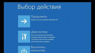
- Select specific Windows 10 boot options and click the Restart Now button.
- After restarting, wait until the Windows 10 boot menu appears.
 Select the desired action
 - In the boot menu, give the command “Diagnostics - Advanced Settings - UEFI Firmware Settings”.
 Go to EFI settings in boot menu
 - Confirm BIOS startup.
 Confirm startup in BIOS/UEFI mode
The PC or laptop will start in UEFI where you can select the advanced BIOS mode.
Calling the Windows 10 emergency boot menu without logging in
This method is suitable if the system cannot start a new session, for example, due to incompatibility of any drivers or applications with Windows 10.
Do the following.

Video: Common methods of entering BIOS under Windows 10
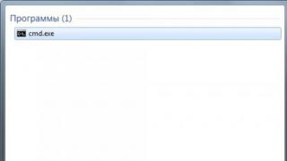
Entering BIOS/UEFI mode using the Windows 10 command line
Do the following.

The system launcher "shutdown.exe" is a tool that allows you to close your current Windows session and shut down the OS. By running the ShutDown.exe program from the C:\Windows\ folder, you will also allow the system to shut down correctly without losing data - even when, for example, if the system is infected with a virus that has blocked the Windows Start button and taskbar, you still need to restart normally PC.
Other options for entering BIOS
There are also older ways to get into the BIOS - connect a keyboard with an outdated PS/2 interface, or switch the jumper on the motherboard of a PC or laptop.
Reset BIOS using jumper
If entering the BIOS is not available due to the manufacturer’s settings, you need to switch the jumper on the motherboard back and forth, turning on the PC each time, so that the BIOS firmware works a little.
 Move the CMOS jumper to a different position or remove it
 Connecting a PS/2 keyboard to work with a PC
First of all, this problem faces owners of PCs and laptops that already have a version of Windows 10 and UEFI firmware instead of BIOS, but have a PS/2 keyboard lying around, purchased 10–15 years ago.
By default, the BIOS/UEFI is already configured to work with USB devices - by connecting your adapter to any of the USB ports, you get a working PS/2 keyboard and/or mouse.
Today there are practically no computers left that are not equipped with USB ports. Overly outdated “system units” and laptops from the distant 90s don’t count - people threw them away, and there is no point in remembering such computers. Judge for yourself: who needs computers with Windows 95/98, having a Pentium 1/2/3 processor with a 300 MHz frequency, 16–64 MB of RAM and a 10 GB hard drive? And there are not very many programs for Windows 9x.
Based on the above, connecting keyboards and mice with an outdated PS/2 plug is easier to do using a special PS/2-USB adapter.
 Combined USB-PS/2 adapters allow you to connect a mouse and keyboard to one port
 There are also reverse adapters that selectively connect mice and keyboards to PC “system units” that have the PS/2 interface itself. Both a wired mouse and a nano-receiver (or Bluetooth module) from a wireless mouse or keyboard are connected to the USB port on the cord. If you connect a mouse or keyboard to the wrong socket through such a converter, the mouse and keyboard themselves will not work; do not confuse the devices.
 Unlike universal adapters, these converters are selective to the type of device
 Adapters for connecting wireless mice and keyboards to the PS/2 socket on the PC system unit allow you to get rid of the age-old problem of wires and cables - fraying of the “cores” at bends, leading to the device not working.
You can order such adapters on the Internet, for example, in the Ozon or AliExpress store - the latter, by the way, carries many goods from China, including various small items, to Russia for free, final delivery is carried out to the Russian Post office closest to to the user. In Russian hypermarket chains, for example, Yulmart or DNS, there is also a lot of this stuff. Don't create unnecessary problems for yourself.
The blue-violet adapter, like the PS/2 connector itself, means that you are working with a keyboard. The green adapter and connector are the PS/2 interface for the mouse.
Today, USB keyboards and mice are actively replacing their outdated PS/2 counterparts. On a more or less modern PC or laptop, you no longer need to do anything.
You should not connect other devices via a “reverse” adapter (for example, a flash drive) - the PS/2 bus was not designed for high-speed data streams of tens and hundreds of megabits. The performance of the PS/2 interface is enough to control the mouse pointer and enter text from the keyboard - it was originally “tailored” for input devices. At worst, you can try connecting a joystick, but its correct operation is not guaranteed.
Is it possible to enter BIOS without restarting Windows
To enter the BIOS, any version of Windows must end the current session and enter a mode in which the power of the PC or laptop can be forcibly turned off (if required). Give the command “Start - Shut down - Restart” or turn off your PC or laptop by pressing and quickly releasing the power button (if the power button action is configured to shut down Windows 10).
In the MS-DOS operating system, the way to go directly to the BIOS was extremely simple - the user pressed the Reset button on the system unit, and when restarting the PC, in turn, a hot key (most often Del) was used. Before this, it was necessary to complete all read/write operations on the disks.
What to do if you can’t enter the BIOS
PC motherboards, laptop mainboards and tablet monoboards are quite reliable, and you should not have any difficulties entering the BIOS. However, entering the BIOS, or rather, not starting a PC or gadget with Windows 10, is mainly due to the following reasons.
- Failure of the ROM chip(s) in which the BIOS firmware is written. On system systems, the ROM chip is often not soldered into the motherboard, but has a special socket block that allows it to be removed and replaced. If you are technically savvy and have at least a little experience in servicing and replacing components, you can take the risk of changing the ROM yourself by ordering it on the manufacturer’s website or in popular Chinese stores, or by purchasing a BIOS chip directly from the service center in your city. On laptops and tablets, replacement mainly helps by re-soldering it on a special soldering station, available in every computer service center that provides a full range of PC repair services, including replacing capacitors on boards.
- Accidental flashing (updating) of the BIOS to an incompatible version. If you dare to update the BIOS version yourself, or even change the BIOS to UEFI in the hope that previously inaccessible functions will open and the mouse will work, such an action is often refused recklessly, because the ROM parameters may not be so perfect as to “pull” the graphics UEFI firmware interface. Restoring (reprogramming) the ROM is also carried out by the service center.
- You press the wrong key or key combination to enter the BIOS. Check the assignment of the key(s) to enter the BIOS specifically for your BIOS version and/or laptop or tablet manufacturer.
- The manufacturer of the PC, laptop or tablet motherboard has closed (classified) the ability to enter the BIOS using a special key combination that is not mentioned in the instructions. This is a very rare case when service centers, in pursuit of profit, can agree with PC and gadget manufacturers not to indicate either in the instructions for the device itself or on the display with the corresponding inscription before starting the OS, how the user can get into the BIOS.
- The PC keyboard (or external tablet keyboard) does not have time to “come to life” when the transition to launching Windows 8.1/10 is too fast. The methods listed above will help here.
- The manufacturer/seller has entered a password that prevents you from entering the BIOS. This is done for commercial reasons - so that in the event of any actions, including reinstalling Windows, the user will pay for such an action. Resetting the settings using the CMOS jumper on the PC motherboard will help here.
- The keyboard is simply faulty. Repair or replace it. Perhaps a certain group of keys does not work, including, say, the Del, F2 or similar key. Old “system systems” did not work at all without a keyboard.
- You pressed the required key (or combination of keys) too late - the OS has already loaded (Windows, MS-DOS, Linux, Android x86, LiveCD/DVD/USB loader or its equivalent, installation/update program for the corresponding OS, etc.) . Wait for the OS (or a tool that emulates its operation) to load and normally end the session that just started. Wait until the PC resets - this is indicated by the logo of the manufacturer and/or distributor of computers of your series/batch appearing on the screen.
- The fast boot function interferes. It needs to be disabled.
Video: problems entering the BIOS - the built-in keyboard does not work well
How to disable fast boot in Windows 10
Do the following.

Restart your PC or tablet. Most likely, before starting Windows 10, you will still have the opportunity to enter the BIOS/EFI using the key, according to the instructions for your computer or gadget.
Errors when entering BIOS
BIOS, like any program (or software package, operating system), including your Windows 10, contains many errors. It won’t hurt to know them if entering the BIOS and/or starting a PC/laptop is accompanied by the BIOS refusing to control a particular device, or the PC refusing to start Windows.
| Message | Description of the problem |
|---|---|
| 8042 Gate A20 Error | Keyboard controller problem (you need to replace the controller or motherboard) |
| Address Line Short | Problem with motherboard expansion cards (possible short circuit; if after checking it fails to boot, you need to change the motherboard) |
| BIOS ROM Checksum Error - System Halt | Checksum error of the permanent memory chip (it is necessary to reflash the chip or replace it) |
| BIOS Update For Installed CPU Failed | BIOS version mismatch with specific processor model |
| Bad PnP Serial ID Checksum | Plug and Play device checksum error (remove the devices, carefully inspect and install again; if this does not help, you need to change the faulty devices) |
| Boot Error - Press F1 To Retry Disk Boot Failure, Insert System Disk And Press Enter | The boot disk is not detected (this often happens if the BIOS Setup has a floppy drive or floppy drive as the first boot sector, and when the computer is turned on, this drive contains a non-system disk or floppy disk - this often happens when, for example, they are watching a movie with disk or listen to music, and then forget to remove the disk. You need to remove the disk and restart the computer, or better yet, in the settings, make it boot from the computer’s hard drive) |
| Bus Time Out NMI At Slot XXX | Happens if EISA bus is installed (try rebooting) |
| CH2 Timer Error | Second timer initialization problem (check peripherals) |
| CMOS Battery Failed | The CMOS battery is dead (replace the battery) |
| CMOS Battery Has Failed | Likewise |
| CMOS Battery State Low | Likewise |
| CMOS Checksum Bad (Error, Failure) | CMOS chip checksum error (check the battery, if that doesn’t help, reprogram the BIOS chip) |
| CMOS Date/Time Not Set | Errors when setting the system time and date (fix the error in the BIOS, check the functionality of the battery) |
| CMOS Display Type | The system monitor characteristics are incorrectly specified in the BIOS |
| CMOS Memory Size Mismatch | |
| CMOS System Options Not Set | The contents of the CMOS memory are damaged (check the battery, it may require flashing) |
| Cache Memory Bad, Do Not Enable Cache | Cache error (replace chip) |
| Checking NVRAM | Information that the system is updating the computer configuration (if it appears frequently, check the motherboard battery) |
| DMA#1(2) Error | Error initializing the DMA channel (possibly a problem due to the connected peripheral device; the motherboard may need to be changed) |
| DMA Bus TimeOut | The system does not receive a response to the DMA controller request (check peripherals and replace faulty ones) |
| DMA Error | DMA controller error (you may have to change the motherboard) |
| Display Type Has Changed Since Last Boot | |
| Drive X: Error | Problems with the hard drive (check the BIOS settings, cable; if the drive is damaged, format it, or better yet, buy a new one) |
| Drive X: Failure | The hard drive cannot be initialized (check the BIOS settings, cable; if the drive is damaged, format it) |
| ECC Error | Problems with RAM (memory needs to be replaced) |
| EISA CMOS Inoperational | EISA board CMOS memory chip error (check battery or replace chip) |
| EISA Configuration Checksum Error | EISA board CMOS memory checksum error (check BIOS settings and battery) |
| EISA Configuration Is Not Complete | EISA board CMOS memory chip error (check BIOS settings) |
| Error Encountered Initializing Hard Drive | Problems with initializing the IDE hard drive (check the BIOS settings, the correct jumper settings; if this does not help, replace the device) |
| Error Initializing Hard Drive Controller | Problems with initializing the IDE controller (check jumpers, BIOS settings) |
| Expansion Board Not Ready At Slot XXX | Problems with initializing the board in slot XXX (check the connection, the board or the slot itself may be faulty) |
| Extended RAM Failed At Offset: XXX | Error initializing extended memory (check connections, or replace memory) |
| FDD Controller Failure | Floppy drive controller initialization error (check connections or replace controller) |
| Floppy Disk Controller Resource Conflict | A conflict between the floppy drive controller and another device (you need to disconnect the device, work, and then connect it again) |
| HDD Controller Failure | IDE controller initialization error (check jumpers, BIOS settings) |
| Hard Disk Install Failure | Problems with initializing the IDE hard drive (check the BIOS settings, jumpers, cables, if that doesn’t help, change the faulty device) |
| Hard Disk Diagnosis Failure | Problems with hard drive initialization (check BIOS settings, jumpers, cables, if that doesn’t help, change the faulty device) |
| Hard Disk Fail (20) Hard Disk Fail (40) | Likewise |
| I/O Card Parity Error at XXX | Expansion board parity error (check board installation) |
| INTR #1 Error | Problems with initializing the first channel of the interrupt controller (IRQ0-IRQ7) |
| INTR #2 Error | Problems with initializing the second channel of the interrupt controller (IRQ8-IRQ15) |
| Incorrect Drive A/B - Run Setup | Floppy drive initialization error (check cable, BIOS settings) |
| Disabled Drive Specification | The hard drive is damaged or, if it is new, is not partitioned (use the FDisk command) |
| Invalid Media In Drive X: | Likewise |
| Invalid System Configuration Data | Error in Plug and Play device configurations (reset the data using the Reset Configuration Date option) |
| Invalid System Configuration Data - Run Configuration Utility Press F1 to Resume, F2 to Setup | Likewise |
| K/B Interface Error | Keyboard problem (check connection) |
| Keyboard Error | Likewise |
| Keyboard Error Or No Keyboard Present | Problems with keyboard operation (see if any key is pressed) |
| Keyboard Failure, Press To Continue | Likewise |
| Keyboard Is Locked Out - Unlock The KeyKeyboard Is Locked | Sticky keys on the keyboard |
| Memory Address Error at XXX | |
| Memory Parity Error at XXX | Likewise |
| Memory Size Decreased | The amount of RAM is incorrectly specified in the BIOS. |
| Memory Size Has Changed Since Last Boot | Likewise |
| Memory Size Increased | Likewise |
| Memory Test Fail | Problems with RAM (check the power supply and the memory itself) |
| Memory Verify Error at XXXX | Likewise |
| Missing Operation System | |
| Monitor Type Does Not Match CMOS - Run Setup | The system monitor is incorrectly specified in the BIOS |
| NVRAM Checksum Error | NVRAM memory error (check BIOS settings and battery) |
| NVRAM Cleared | Likewise |
| NVRAM Data Invalid | Likewise |
| No ROM Basic | Error when trying to boot the system from the hard drive (possibly caused by a virus, you will have to partition the disk again with the loss of all data) |
| Off Board Parity Error | Trying to boot from a floppy disk when there is no system floppy disk in the drive (remove the floppy disk) |
| Offending Address Not Found | Problems with devices not integrated into the motherboard (processor, RAM...) |
| Offending Segment | Unknown device error (most likely problems with data transfer or a conflict when accessing ports - check the BIOS) |
| On Board Parity Error | Problems with devices integrated into the motherboard (hard drive controller, PCI bus...) |
| Onboard PCI VGA Not Configured For Bus Master | Problem with integrated video card |
| Operating System Not Found | Error when trying to load the operating system - it was not found (possibly caused by a virus, you will have to partition the disk again with the loss of all data) |
| Override Enabled - Default Loaded | The system cannot boot with the BIOS values set, all parameters will be reset to factory values |
| PCI I/O Port Conflict | PCI bus device conflict - trying to use the same I/O port (update hardware configuration) |
| PCI IRQ Conflict | Likewise |
| PCI Memory Conflict | PCI bus device conflict - trying to use the same memory area (update hardware configuration) |
| Parallel Port Source Conflict | Conflict between devices using parallel port (update hardware configuration or configure manually) |
| Parity Error | RAM parity error |
| Press A Key To Reboot | Problems booting the system (if the message appears frequently, change the motherboard) |
| Press ESC To Skip Memory Test | Pressing the ESC key will check the RAM using an abbreviated program |
| Press F L To Disable NMI, F2 To Reboot | Interrupt controller problem - it is impossible to determine the device that submitted a request for a non-maskable NMI interrupt |
| Primary Boot Device Not Found | The device configured in the BIOS as the primary boot disk was not found (there may be no system floppy disk or disk - insert the floppy disk or disk, or make the appropriate settings in the BIOS) |
| Primary Master Hard Disk Failure | Problems with testing the Primary Master hard drive (check the BIOS settings, cables, jumpers, try connecting another drive; you may have to change the cable or hard drive) |
| Primary Slave Hard Disk Failure | Problems with testing the Primary Slave hard drive (check the BIOS settings, cables, jumpers, try connecting another drive; you may have to change the cable or hard drive) |
| Primary/Secondary IDE Controller Resource Conflict | Device conflict - the IDE controller is accessing already occupied computer resources (update the hardware configuration or configure it manually) |
| RAM Parity Error - Checking For Segment | RAM parity error (maybe the memory stick is installed incorrectly, try setting the slowest memory settings in the BIOS) |
| Real Time Clock Error | Errors in setting the system time and date (check the battery, BIOS settings, if that doesn’t help, change the motherboard) |
| Real Time Clock Failure | Likewise |
| Secondary Master Hard Disk Failure | Problems with testing the Secondary Master hard drive (check the BIOS settings, cables, jumpers, try connecting another drive; you may have to change the cable or hard drive) |
| Secondary Slave Hard Disk Fail | Problems with testing the Secondary Slave hard drive (check the BIOS settings, cables, jumpers, try connecting another drive; you may have to change the cable or hard drive) |
| Serial Port 1 Resource Conflict | Conflict of devices using serial port COM1 (update hardware configuration or configure manually) |
| Serial Port 2 Resource Conflict | Conflict of devices using serial port COM2 (update hardware configuration or configure manually) |
| Should Be Empty But EISA Board Found | EISA expansion card error (update hardware configuration or configure manually) |
| Should Have EISA Board But Not Found | EISA expansion board error - does not respond to system requests (update the hardware configuration or configure manually, if that does not help, replace the faulty hardware) |
| Slot Not Empty | An unknown expansion card was detected on the ELSA bus (check your BIOS settings) |
| Software Port NMI Inoperational | Problems with the NMI software interrupt port (check the BIOS settings, you may have to change the motherboard) |
| State Battery CMOS Low | |
| Static Device Resource Conflict | |
| System Battery Is Dead | The CMOS memory battery is low (replace the battery) |
| System Battery Is Dead - Replace And Run Setup | Likewise |
| System CMOS Checksum Bad | CMOS memory checksum error (check the battery, replace if necessary, if that doesn’t help, change the motherboard) |
| System Device Resource Conflict | Device conflict (update hardware or configure manually) |
| System Halted, (CtrlAltDel) To Reboot | Stopping the system (press Ctrl+Alt+Del to reboot the system) |
| System RAM Failed At Offset: XXXX | Error initializing RAM (maybe the memory stick is installed incorrectly, try setting the slowest memory settings in the BIOS) |
| Type Display CMOS Mismatch | The system monitor type is incorrectly specified in the BIOS |
| Uncorrectable ECC DRAM Error | Problems with RAM (you may need to replace the memory) |
| Unknown PCI Error | Unknown PCI bus error (if all PCI cards are working normally, change the motherboard) |
| Update Failed | Failed to update information about new Plug@Play devices (check battery or replace system board) |
| Update OK! | Information about new devices was updated successfully |
| Wrong Board In Slot | EISA expansion board error (check BIOS settings or replace faulty devices) |
BIOS will help where Windows - or another OS - is already powerless. If there were no BIOS, it would be impossible to revive the PC in emergency situations. Great work to you - and less problems associated with its downtime!
If you were looking for BIOS settings in pictures, then you have come to the right address.
The changes made will be protected by a lithium battery built into the motherboard and maintaining the required parameters in the event of a loss of voltage.
Thanks to the program, it is possible to establish stable interaction between the operating system (OS) and PC devices.
Attention! The present Boot network configuration section allows you to adjust parameters related to system boot speed and keyboard and mouse settings.
After finishing work or familiarizing yourself with the Bios Setup Utility menu, you need to press the hot Exit key, which automatically saves the changes made.
Section Main - Main Menu
Let's start working with the MAIN section, which is used to modify settings and adjust timing indicators.
Here you can independently configure the time and date of your computer, as well as configure connected hard drives and other storage devices.

To reformat the operating mode of the hard drive, you need to select the hard drive (for example: “SATA 1”, as shown in the figure).
- Type - This item indicates the type of connected hard drive;
- LBA Large Mode- is responsible for supporting drives with a capacity of more than 504 MB. So the recommended value here is AUTO.
- Block (Multi-Sector Transfer) - For faster operation here, we recommend selecting the AUTO mode;
- PIO Mode - Enables the hard drive to operate in legacy data exchange mode. It would also be best to select AUTO here;
- DMA Mode - gives direct memory access. To get faster read or write speed, select AUTO;
- Smart monitoring - this technology, based on an analysis of the drive’s operation, can warn of a possible disk failure in the near future;
- 32 bit Data Transfer - The option determines whether the 32-bit data exchange mode will be used by the standard IDE/SATA controller of the chipset.

Everywhere, using the “ENTER” key and arrows, the Auto mode is set. The exception is the 32 Bit Transfer subsection, which requires the Enabled setting to be fixed.
Important! It is required to refrain from changing the “Storage Configuration” option, which is located in the “System information” section and not to allow correction “SATADetectTimeout".

Advanced section - Additional settings
Now let's start setting up the basic PC components in the ADVANCED section, which consists of several sub-items.
Initially, you will need to set the necessary processor and memory parameters in the system configuration menu Jumper Free Configuration.

By selecting Jumper Free Configuration, you will be taken to the Configure System Frequency/Voltage subsection, where you can perform the following operations:
- automatic or manual overclocking of the hard drive - AI Overclocking;
- changing the clock frequency of memory modules - ;
- Memory Voltage;
- manual mode for setting chipset voltage - NB Voltage
- changing port addresses (COM,LPT) - Serial and Parallel Port;
- setting controller settings - Onboard Devices configuration.

Power Section - PC Power
The POWER item is responsible for powering the PC and contains several subsections that require the following settings:
- Suspended Mode- set automatic mode;
- ACPI APIC- set Enabled;
- ACPI 2.0- fix the Disabled mode.

BOOT section - boot management
Here you can determine the priority drive, choosing between a flash card, disk drive or hard drive.

If there are several hard drives, then in the Hard Disk sub-item the priority hard drive is selected.
The PC boot configuration is set in the Boot Setting subsection, which contains a menu consisting of several items:

Selecting a hard drive
The PC boot configuration is set in the Boot Setting subsection,

- Quick Boot– acceleration of OS loading;
- Logo Full Screen– disabling the screen saver and activating the information window containing information about the download process;
- Add On ROM- setting the order on the information screen of modules connected to the motherboard (MT) via slots;
- Wait For 'F1' If Error- activation of the function of forced pressing “F1” at the moment the system identifies an error.
The main task of the Boot section is to determine boot devices and set the required priorities.
- ASUS EZ Flash– using this option, you have the opportunity to update the BIOS from such drives as: floppy disk, Flash disk or CD.
- AINET– using this option, you can obtain information about the cable connected to the network controller.

Exit section - Exit and save
Particular attention should be paid to the EXIT item, which has 4 operating modes:
- Save Changes– save the changes made;
- Discard Changes + EXIT– leave the factory settings in effect;
- Setup Defaults– enter default parameters;
- Discard Changes– we cancel all our actions.

The following step-by-step instructions explain in detail the purpose of the main BIOS sections and the rules for making changes to improve PC performance.
Bios setup
Bios Settings - Detailed instructions in pictures
So, you have a boot disk with Windows, now you need to make sure that the computer can boot from it. To do this, you only need to change one parameter in the BIOS.
You can get there immediately after turning on the computer, when the message Press DEL to enter SETUP appears on the monitor, that is, to get into the BIOS you need to press the button while the message is displayed on the monitor Delete.
The inscriptions may be different, there may even be no inscriptions, this should not confuse you. In most cases, the following keys are most often used to get into the BIOS:
Desktops – Delete(In most cases), F1 or F4
Laptops – F1, F2, F3, Delete, Ctrl + Alt + Esc. In the case of laptops, keyboard shortcuts can be very varied, depending on its model. You can find this information either online or by calling technical support.
Be careful, as the inscription on the screen disappears quickly enough, so after turning on the computer, you can immediately press the corresponding key several times (once is enough, but to accurately catch the right moment, pressing it multiple times will not hurt) If you cannot see it on the first try , then restart your computer using the button Reset and try again. When loading begins, a graphic image may appear on the screen that obscures service labels. To remove it, press the Esc key. If everything is done correctly, a window with BIOS settings will appear.
There are different versions of BIOS. Select your option and follow the instructions provided.
1.AMI BIOS (BIOS SETUP UTILITY)
After entering the BIOS settings of this type, you will see the following window:
At the top, enter the section Boot and in the subsection Boot Device Priority in point 1st Boot Device select the option with CDROM.

All. Our BIOS is configured. Now you need to insert the Windows disk into the drive and exit the BIOS after saving the settings you made. To do this, press the F10 key, select Yes in the dialog box that appears and press Enter.

2. AWARD (PHOENIX) BIOS
Choose a section Boot(Sometimes Advanced). Find the parameter CD-ROM and move it to the very top. In this BIOS version, to move CD-ROM To reach the top position, press the + key twice.

It should look like in the picture:
Save your settings and exit the BIOS. To do this, go to the tab Exit and select Exit Saving Changes:

3. Another option AWARD (PHOENIX) BIOS
Here we are interested in the section Advanced BIOS Features.

We go to this section and look for the item First Boot Device. Then at this point we set the computer to boot from CDROM.

Once you have configured BIOS, you need to insert a boot disk with Windows into the drive and save the settings BIOS. To do this, press the F10 key, select Yes in the window that appears and press Enter.
4. UEFI (EFI) BIOS
The main UEFI BIOS window looks like the picture below. In the upper right corner of the window you can set the interface language - I selected “Russian”. Left-click on the button once Output/Additional.

In the window that appears, select “Additional mode” with the left mouse button.

A UEFI BIOS advanced mode window will appear, in which you need to select the “Boot” menu item, as shown in the picture below.

You will see the menu items shown below in the picture. Considering that Windows will be installed from a boot disk, left-click on the button opposite “Boot option #1”.

In the small window that appears, select your DVD-ROM. My DVD drive (disc reader) is named after the company that made it - Optiarc DVD RW. This is the one you need to choose. The name of your DVD drive, of course, may be different.

This completes the BIOS settings required to install Windows from a disk. To save the settings, click on the “Exit” button. In the window that appears, you must select “Save changes and reset.”

REMEMBER! After installing Windows, you need to enter the BIOS again and return booting from the hard drive.
Most often, we think about the BIOS (Basic Input/Output System) only when we need to reinstall the operating system and need to somehow set it to boot from a disk or flash drive. I often wrote about this in articles such as:, and others. Now I want to put it together and refer only to this article when necessary. This article will be useful for all BIOS versions and for different companies. A kind of single reference book
The first thing you need to know is that BIOS is divided by manufacturer and version.
To change boot method in BIOS- You must first enter it.
You can, of course, find out what version and manufacturer of your BIOS is from the manual that came with your computer.
You can also find out by looking at the line at the top of the black screen when loading (the manufacturer will be indicated there).
Well, then enter the BIOS, knowing what it is for you.
Some BIOS versions do not have such a screen showing lines. There’s just a logo there and at the bottom it says something like “Press F2 to enter SETUP,” which means press F2. If there is just a logo and there are no inscriptions, press ESC, and then del or f2
Here is a small list of manufacturers and keyboard shortcuts for entering BIOS:
Also at the bottom of the black screen there are keys for entering the BIOS and for displaying a list that contains available devices for booting and so that you can boot from it. But more about him at the end of the article.

As you can see, most often you need to press the key F2 or Del.
Now you need to load a flash drive or disk.
Let's look at a few examples that differ from the BIOS manufacturer.
Setting up Award Bios to boot from a flash drive or disk:
The main window looks like this, in which we need the second item:

Further depends on the firmware version. In one case, you will need to go to an item similar to “Boot Seq & Floppy Setup”

in another case, you don’t need to go anywhere - everything will be right before your eyes

Clicks on First Boot Device(First boot device), click Enter and a window like this will appear

in which you need to select the disk or flash drive that will launch first. You can specify a Second boot device, for example, but usually the BIOS itself fills in this data.
On a note:
If you select a flash drive, then, among other things, you also need to go to the “Hard Disk Boot Priority” item and move our flash drive to the very top using the “+” and “-” or “PageUp” and “PageDown” buttons:

It is also worth remembering that In order for the BIOS to see the flash drive, it must be connected before turning it on or before rebooting
Then press “F10” (see the exact key in the hint at the bottom of the screen called “Save”, “Exit”) or go to the main BIOS menu and select “Save and Exit Setup”. In the red window, select “Yes” using the “Y” button on the keyboard and press “Enter”

The computer will reboot and when booting from the Windows installation disk, the following request may appear for a few seconds: “Press any key to boot from CD or DVD...”

Which translates to “Press any button to boot from a CD or DVD.”
This means that if you do not press any button on the keyboard at this moment, the computer will continue to boot from the next device on the list.
Another version of this BIOS:
I've only seen this on old computers from ten years ago, before 2003. The main menu looks like this:

To configure the boot order, you need to go to the menu BIOS FEATURES SETUP:

At this point, use the PageUp and PageDown buttons (or Enter and arrows) to select what to put first - CDROM or flash drive. DO NOT forget about the second and third device
And further:


How to choose what to boot from in AMI BIOS
If, after entering the Bios, you see such a screen, it means you have AMI BIOS:

Use the right arrow button on the keyboard to move to the Boot tab:

Go to "Hard Disk Drives" and in the line "1st Drive" (may be called "First Drive") select a disk or flash drive:

Next, go to "Boot Device Priority", go to "1st Boot Device" and select from the list what you selected in the previous tab (i.e. if you selected a flash drive in Hard Disk Drives, then you need to specify it here too. This is important! )

To boot from a CD/DVD disk, you need to select “ATAPI CD-ROM” (or simply “CDROM”) in this menu; there is no need to go to the previous “Hard Disk Drives” menu.
Now we save the results with the “F10” button or go to the BIOS “Exit” section and select “Exit Saving Changes”.
Another AMI BIOS, but everything is clear here:

Setting up Phoenix-Award Bios to boot from a flash drive
If, after entering the Bios, you see a screen like this, then you have a Phoenix-Award BIOS:

Go to the “Advanced” tab and opposite “First Boot Device” set what you need (flash drive or disk):

Save with F10 key

Setting up EFI (UEFI) Bios with a graphical interface for booting from a flash drive
Now this won’t surprise anyone. Almost all new computers are equipped with a similar shell. You can read more about it in the article.
When loading, at the bottom of the screen there is a “Boot Priority” section, where you can use the mouse (by dragging) the pictures to set the desired boot order.
You can also click the “Exit/Advanced mode” button in the upper right corner and select Advanced mode in the window that appears.

Next, go to the “Boot” tab and in the section Boot Option Priorities in the “Boot Option #1” field, set the default boot device to be a flash drive, DVD-ROM, hard drive or other available device.

How to boot from a flash drive or disk without entering BIOS
This is what I wrote about almost at the very beginning of the article.
This is when you need to press a key once and a window will appear with a boot selection. This method does not change the BIOS settings.
Usually Award BIOS prompts you to press "F9" to bring up the boot menu, and AMI asks you to press "F8". On laptops this may be the “F12” key.
In general, look at the bottom line and look for items like “Press F8 for BBS POPUP” or “Press F9 to Select Booting Device after POST”.

Why can't I boot from a flash drive into BIOS?
Possible reasons: 
On older computers there is no way to boot from USB flash drives at all. If a newer BIOS does not exist, then the project may help.
1) Download the latest version of "Plop Boot Manager" from the link above and unpack it.
2) The archive contains the following files: plpbt.img – an image for a floppy disk, and plpbt.iso – an image for a CD.
3) Write the image to disk and boot from it (or from a floppy disk).
4) A menu will appear in which we select our flash drive and boot from it.
A small explanation of disk designations when selecting:
Do not forget, after you have done what you wanted (namely, why you changed the boot in the BIOS) - return the boot settings back so that the computer boots from the hard drive.