Hello.
Note
At the end of the article there are two videos that roughly duplicate the content of the article and demonstrate the operation of the device.
I can assume that many local residents are attracted to electronic devices based on vacuum tubes (I personally am pleased with the warmth, pleasant light and monumentality of lamp structures), but at the same time, the desire to design something warm and lamp-like with one's own hands often breaks down against the fear of contacting high voltages or trouble finding specific transformers. And with this article I want to try to help those who suffer, i.e. describe lamp low anode voltage design, very simple circuitry, common components and no need for an output transformer. At the same time, this is not just another headphone amplifier or some kind of overdrive for a guitar, but a much more interesting device.
"What kind of structure is this?" - you ask. And my answer is simple: Super regenerator!".
Superregenerators are a very interesting type of radio receivers, which are distinguished by their simplicity of circuits and good characteristics comparable to simple superheterodynes. Subjects were extremely popular in the middle of the last century (especially in portable electronics) and they are primarily designed to receive stations with amplitude modulation in the VHF band, but they can also receive stations with frequency modulation (i.e., to receive those same conventional FM stations).
The main element of this type of receivers is a super-regenerative detector, which is both a frequency detector and a radio frequency amplifier. This effect is achieved through the use of adjustable positive feedback. I don’t see the point in describing the theory of the process in detail, since “everything has been written before us” and is mastered without problems at this link.
Further in this set of bookoffs, emphasis will be placed on the description of the construction of a proven design, because the circuits encountered in the literature are often more complicated and require a higher anode voltage, which is not suitable for us.
I began the search for a circuit that satisfies the set requirements from Comrade Tutorsky's book "The Simplest Amateur VHF Transmitters and Receivers" of the 1952 model. There was a circuit for a super-regenerator, but I did not find the lamp that was proposed to be used, and with the analog, the circuit did not start up normally, so the search was continued.
Then this one was found. It already suited me better, but there was a foreign lamp in it, which is even more difficult to find. As a result, it was decided to start experiments using a common exemplary analogue, namely, a 6n23p lamp, which feels great in VHF and can operate at a not too high anode voltage.
Based on this diagram:

And after a series of experiments, the following circuit was formed on a 6n23p lamp:

This design works immediately (with proper installation and a live lamp), and gives good results even on ordinary in-ear headphones.
Now let's go through the elements of the circuit in more detail and start with the 6n23p lamp (double triode):
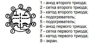
To understand the correct location of the legs of the lamp (information for those who have never dealt with lamps before), you need to turn it with the legs towards you and the key down (sector without legs), then the beautiful view that appears in front of you will correspond to the picture with the pinout of the lamp (it works and for most other lamps). As you can see from the figure, there are two triodes in the lamp, but we need only one. You can use any, there is no difference.
Now let's go through the diagram from left to right. It is best to wind the inductors L1 and L2 on a common round base (mandrel), a medical syringe with a diameter of 15 mm is ideal for this, and it is desirable to wind L1 over a cardboard tube that moves with little effort along the syringe body, which ensures adjustment of the connection between the coils. As an antenna, you can solder a piece of wire to the extreme output of L1, or solder the antenna jack and use something more serious.
It is advisable to wind L1 and L2 with a thick wire to increase the quality factor, for example, with a wire of 1 mm or more in 2 mm increments (special accuracy is not needed here, so you don’t have to bother with each turn). For L1, you need to wind 2 turns, and for L2 - 4-5 turns.
Next come capacitors C1 and C2, which are a two-section air-dielectric variable capacitor (CPV), it is an ideal solution for such circuits, CFC with a solid dielectric is undesirable. Probably, KPI is the rarest element of this circuit, but it is quite easy to find it in any old radio equipment or at flea markets, although it can also be seen with two ordinary capacitors (necessarily ceramic), but then you will have to adjust using an impromptu variometer (a device for smoothly changing inductance). KPI example:

We need only two KPI sections and they necessarily must be symmetrical, i.e. have the same capacity in any adjustment position. Their common accurate will be the contact of the moving part of the KPI.
This is followed by a quenching circuit made on the resistor R1 (2.2 MΩ) and the capacitor C3 (10 pF). Their values can be changed within small limits.
Coil L3 acts as an anode choke, i.e. high frequency is not allowed to pass further. Any choke will do (but not on an iron magnetic circuit) with an inductance of 100-200 μH, but it is easier to wind 100-200 turns of a thin copper enameled wire on the body of a worn-out powerful resistor.
Capacitor C4 serves to separate the DC component at the output of the receiver. Headphones or an amplifier can be connected directly to it. Its capacity can vary within fairly large limits. It is desirable that C4 be film or paper, but it will also work with ceramic.
Resistor R3 is a conventional 33kΩ potentiometer, which serves to regulate the anode voltage, which allows you to change the lamp mode. This is necessary for a more precise adjustment of the mode for a specific radio station. You can replace it with a fixed resistor, but this is undesirable.
This completes the elements. As you can see the circuit is very simple.
And now a little about the power supply and installation of the receiver.
Anode power supply can be safely used from 10V to 30V (more is possible, but it is already a little dangerous to connect low-resistance equipment there). The current there is quite small and a PSU of any power with the required voltage is suitable for power supply, but it is desirable that it be stabilized and have a minimum of noise.
And another prerequisite is the power supply of the incandescent lamp (in the picture with the pinout it is indicated as heaters), since without it it will not work. Here, more currents are needed (300-400 mA), but the voltage is only 6.3V. Both AC 50Hz and DC voltage are suitable, and it can be from 5 to 7V, but it is better to use the canonical 6.3V. Personally, I have not tried using 5V on the glow, but most likely everything will work fine. Heat is supplied to legs 4 and 5.
Now about the installation. Ideally, all circuit elements are located in a metal case with ground connected to it at one point, but it will work without a case at all. Since the circuit operates in the VHF band, all connections in the high-frequency part of the circuit should be as short as possible to ensure greater stability and quality of the device. Here is an example of the first prototype:

With this installation, everything worked. But with a metal case, the chassis is a little more stable:

For such circuits, surface mounting is ideal, since it gives good electrical characteristics and allows you to make corrections to the circuits without much difficulty, which is no longer so easy and accurate with the board. Although my installation can not be called accurate.
Now for the setup.
After you are 100% sure that the installation was correct, you applied voltage and nothing exploded or caught fire - this means that the circuit most likely works if the correct element values \u200b\u200bare used. And you will most likely hear noises in the headphones. If in all positions of the KPI you do not miss the stations, and you are sure that you receive broadcast stations on other devices, then try changing the number of turns of the L2 coil, by doing this you will rebuild the resonance frequency of the circuit and possibly fall into the desired range. And try turning the knob of the variable resistor - that might help too. If nothing helps at all, then you can experiment with the antenna. This completes the setup.
At this stage, all the most basic has already been said, and the inept narrative presented above can be supplemented with the following videos, which illustrate the receiver at different stages of development and demonstrate the quality of its work.
Pure tube version (at the breadboard level):
Option with the addition of ULF to the IC (already with the chassis):
Recently, there has been a great interest in antique and retro radio equipment. The items of the collections are both copies of retro radio equipment of the 40-60s, and real antique devices of the 10-30s of the last century. In addition to collecting original items, there is a growing interest in collecting and making so-called replicas. This is a very interesting direction of amateur radio creativity, but first let's explain the meaning of this term.
There are three concepts: original, copy and replica of an antique item. The term "original" needs no description. A copy is a modern repetition of some antique product, down to the smallest details, materials used, design solutions, etc. A replica is a modern product made in the style of products of those years and, if possible, with approximate design solutions. Accordingly, the closer the replica is to the original products in terms of style and detail, the more valuable it is.
Now there are many so-called radio souvenirs on sale, mostly made in China, decorated in the form of retro and even antique radio equipment. Unfortunately, upon closer inspection, it is clear that its value is low. Plastic handles, painted plastic, body material - MDF covered with foil. All this speaks of a very low-grade product. As for their "stuffing", it, as a rule, is a printed circuit board with modern integral elements. The internal installation of such products in terms of quality also leaves much to be desired. The only "advantage" of these products is their low price. Therefore, they may be of interest only to those who, without going into technical subtleties or simply not understanding them, want to have an inexpensive "cool thing" on their desk in their office.
As an alternative, I want to present a receiver design that fully meets the requirements of an interesting and high-quality replica. This is a super-regenerative tube VHF FM receiver (Fig. 1), operating in the frequency range of 87 ... 108 MHz. It is assembled on radio tubes of the octal series, since it is not possible to use lamps with a pin base, older and suitable in style, in this design due to the high operating frequency of the receiver.
Rice. 1. Super-regenerative tube VHF FM receiver
Bronze terminals, control knobs and brass nameplates are an exact copy of those used in products of the 20s of the last century. Some elements of fittings and design are original. All radio tubes of the receiver are open, except for the screens. All inscriptions are made in German. The body of the receiver is made of solid beech. Installation, with the exception of some high-frequency nodes, is also made in a style as close as possible to the original of those years.
The front panel of the receiver has a power switch (ein / aus), a frequency setting knob (Freq. Einst.), a frequency scale with an arrow tuning indicator. The volume control (Lautst.) - on the right and the sensitivity control (Empf.) - on the left are displayed on the top panel. Also on the top panel there is a pointer voltmeter, the backlight of the scale of which is an indication of the power on of the receiver. On the left side of the case there are terminals for connecting the antenna (Antenne), and on the right side there are terminals for connecting an external classical or horn loudspeaker (Lautsprecher).
I want to note right away that the further description of the receiver device, despite the presence of drawings of all the details, is for informational purposes, since the repetition of such a design is available to experienced radio amateurs, and also implies the presence of certain wood and metalworking equipment. In addition, not all elements are standard and purchased. As a result, some installation dimensions may differ from those given in the drawings, as they depend on the elements that will be available. For those who want to repeat this one-to-one receiver and who need more detailed information about the design of certain parts, assembly and installation, drawings are offered, as well as the opportunity to ask a question directly to the author.
The receiver circuit is shown in fig. 2. Antenna input is designed to connect a balanced VHF antenna drop cable. The output is designed to connect a loudspeaker with a resistance of 4-8 ohms. The receiver is assembled according to the 1-V-2 scheme and contains a UHF on a VL1 pentode, a super-regenerative detector and a preliminary UHF on a VL3 double triode, a final UHF on a VL6 pentode and a power supply on a T1 transformer with a rectifier on a VL2 kenotron. The receiver is powered by 230 V.

Rice. 2. Receiver circuit
UHF is a range amplifier with a diversity tuning of the circuits. Its tasks are to amplify the high-frequency oscillations coming from the antenna, and to prevent the penetration into it and radiation into the air of its own high-frequency oscillations of the super-regenerative detector. UHF is assembled on a high-frequency pentode 6AC7 (analogue - 6Zh4). The connection of the antenna with the input circuit L2C1 is carried out using the coupling coil L1. The input impedance of the cascade is 300 ohms. The input circuit in the grid circuit of the VL1 lamp is tuned to a frequency of 90 MHz. The setting is carried out by selecting the capacitor C1. The L3C4 circuit in the anode circuit of the VL1 lamp is tuned to a frequency of 105 MHz. The setting is carried out by selecting the capacitor C4. With this configuration of the circuits, the maximum UHF gain is about 15 dB, and the frequency response unevenness in the frequency range of 87 ... 108 MHz is about 6 dB. Communication with the subsequent cascade (superregenerative detector) is carried out using the L4 coupling coil. Using a variable resistor R3, you can change the voltage on the screen grid of the VL1 lamp from 150 to 20 V and thereby change the UHF transmission coefficient from 15 to -20 dB. Resistor R1 serves to automatically generate a bias voltage (2 V). Capacitor C2 shunting resistor R1 eliminates AC feedback. Capacitors C3, C5 and C6 - blocking. The voltages at the terminals of the VL1 lamp are indicated for the upper position of the resistor R3 engine according to the diagram.
Super Regenerative Detector assembled on the left half of the double triode VL3 6SN7 (analogue - 6H8C). The super-regenerator circuit is formed by an inductor L7 and capacitors C10 and C11. The variable capacitor C10 serves to tune the circuit in the range of 87 ... 108 MHz, and the capacitor C11 - to "lay" the boundaries of this range. In the grid circuit of the triode of the superregenerative detector, the so-called "gridlick" is included, formed by the capacitor C12 and the resistor R6. With a selection of capacitor C12, a damping frequency of about 40 kHz is set. The connection of the super-regenerator circuit with UHF is carried out using the L5 coupling coil. The supply voltage of the anode circuit of the super-regenerator is supplied to the output of the loop coil L7. Inductor L8 - superregenerator load at high frequency, inductor L6 - at low frequency. Resistor R7 together with capacitors C7 and C13 form a filter in the power circuit, capacitors C8, C14, C15 are blocking. The AF signal through the capacitor C17 and the low-pass filter R11C20 with a cutoff frequency of 10 kHz is fed to the input of the preliminary ultrasonic frequency converter.
Preliminary ultrasound assembled on the right (according to the scheme) half of the triode VL3. The cathode circuit includes a resistor R9 for automatically generating a bias voltage (2.2 V) on the grid and a choke L10, which reduces the gain at frequencies above 10 kHz and serves to prevent the penetration of superregenerator quenching pulses into the final ultrasonic frequency converter. From the anode of the right triode VL3, through the coupling capacitor C16, the AF signal is fed to the variable resistor R13, which acts as a volume control.
The power supply provides power to all components of the receiver: an alternating voltage of 6.3 V - to power the incandescent lamps, a constant unstabilized voltage of 250 V - to power the anode circuits of the UHF and the final ultrasonic frequency converter. The rectifier is assembled according to a full-wave circuit on a VL2 5V4G kenotron (analog - 5Ts4S). The rectified voltage ripple is smoothed out by the C9L9C18 filter. The supply voltage of the super-regenerator and the preliminary ultrasonic frequency converter is stabilized by a parametric stabilizer on the resistor R14 and gas-discharge zener diodes VL4 and VL5 VR105 (analogue - SG-3S). The R12C19 RC filter additionally suppresses voltage ripple and zener diode noise.
Construction and installation. UHF elements are mounted on the main chassis of the receiver around the lamp panel. To prevent self-excitation of the cascade, the grid and anode circuits are separated by a brass screen. Communication coils and loop coils are frameless and mounted on textolite mounting racks (Fig. 3 and Fig. 4). Coils L1 and L4 are wound with a silver-plated wire with a diameter of 2 mm on a mandrel with a diameter of 12 mm with a pitch of 3 mm.

Rice. 3. Communication coils and contour coils are frameless, mounted on textolite mounting racks

Rice. 4. Communication coils and contour coils are frameless, mounted on textolite mounting racks
L1 has 6 turns with a tap in the middle and L4 has 3 turns. Loop coils L2 (6 turns) and L3 (7 turns) are wound with a silver-plated wire with a diameter of 1.2 mm on a mandrel with a diameter of 5.5 mm, the winding pitch is 1.5 mm. Loop coils are located inside the coupling coils.
The screen grid voltage of the VL1 lamp is controlled by a pointer voltmeter located on the top panel of the receiver. The voltmeter is implemented on a milliammeter with a total deviation current of 2.5 mA and an additional resistor R5. Subminiature scale backlight lamps EL1 and EL2 (CMH6.3-20-2) are placed inside the milliammeter case.

Rice. Fig. 5. Elements of the super-regenerative detector and preliminary USCH, mounted in a separate shielded block
The elements of the super-regenerative detector and the preliminary UZCH are mounted in a separate shielded block (Fig. 5) using standard mounting racks (SM-10-3). The variable capacitor C10 (1KPVM-2) is fixed on the block wall with glue and a textolite sleeve. Capacitors C7, C8, C14 and C15 are pass-through series KTP. The inductor L6 is connected through the capacitors C7 and C8. The supply voltage to the shielded unit is supplied through the capacitor C15, and the filament voltage is supplied through the capacitor C14. Oxide capacitor C19 - K50-7, inductor L8 - DPM2.4. The inductor L6 is self-made, it is wound in two sections on a Sh14x20 magnetic circuit and contains 2x8000 turns of PETV-2 0.06 wire. Since the choke is sensitive to electromagnetic interference (in particular, from the elements of the power supply), it is mounted on a steel plate above the UHF (Fig. 6) and closed with a steel screen. It is connected with shielded wires. The braid is connected to the body of the super-regenerator unit. For the manufacture of the L10 inductor, an SB-12a armored magnetic circuit with a permeability of 1000 was used, a winding was wound on its frame - 180 turns of PELSHO 0.06 wire. Coils L5 and L7 are wound with a silver-plated wire with a diameter of 0.5 mm with a pitch of 1.5 mm, on a ribbed ceramic frame with a diameter of 10 mm, which is glued using a textolite sleeve into the hole of the lamp panel. The inductor L7 contains 6 turns with a tap from 3.5 turns, counting from the top according to the output circuit, the coupling coil L5 is 1.5 turns.

Rice. 6. Choke mounted on a steel plate above the UHF
The shielded block is attached to the main chassis of the receiver using a threaded flange. The connection of the capacitor C16 and the resistor R13 is made by a shielded wire with the shielding braid grounded near the resistor R13. The rotation of the rotor of the capacitor C10 is carried out using a textolite axis. To ensure the necessary strength and wear resistance of the splined connection of the axis and the C10 capacitor, a cut was made in the axis, into which a fiberglass plate was glued. One end of the plate is sharpened so that it fits snugly into the slot of the capacitor C10. The axle is fixed and pressed against the condenser spline by means of a spring washer laid between the bracket sleeve and the driven pulley fixed on the axle (Fig. 7).

Rice. 7. Shielded block
The vernier is assembled on two brackets fixed on the front wall of the shielded block of the super-regenerator (Fig. 8). Brackets can either be made independently, according to the attached drawings, or you can use a standard aluminum profile with minor modifications. To transmit rotation, a nylon thread with a diameter of 1.5 mm was used. You can use a "harsh" shoe thread of the same diameter. One end of the thread is attached directly to one of the pins of the driven pulley, and the other - to the other pin through the tension spring. Three turns of thread are made in the groove of the leading axis of the vernier. The driven pulley is fixed on the axis so that in the middle position of the variable capacitor C10, the end hole for the thread is located diametrically opposite to the leading axis of the vernier. Both axles are equipped with extension nozzles, fixed to them with locking screws. On the nozzle of the leading axis there is a frequency adjustment knob, and on the nozzle of the slave - a pointer scale indicator.

Rice. 8. Vernier
Most of the elements of the final ultrasonic frequency converter are mounted on the terminals of the lamp panel and mounting racks. The output transformer T2 (TVZ-19) is installed on an additional chassis and is oriented at an angle of 90 ° with respect to the magnetic circuit of the inductor L9 of the power supply. The connection of the control grid of the VL6 lamp with the engine of the resistor R13 is made with a shielded wire with grounding of the shielding braid near this resistor. Oxide capacitor C21 - K50-7.
The power supply (except elements L9, R12 and R14, which are mounted on an additional chassis) is mounted on the main chassis of the receiver. Choke L9 unified - D31-5-0.14, capacitor C9 - MBGO-2 with flanges for mounting, oxide capacitors C18, C19 - K50-7. For the manufacture of the T1 transformer with an overall power of 60 V-A, a Sh20x40 magnetic circuit was used. The transformer is equipped with stamped metal covers. On the top cover there is a panel of the VL2 kenotron together with a brass decorative nozzle (Fig. 9). A mounting block is installed on the bottom cover, where the necessary outputs of the transformer windings and the output of the cathode of the kenotron are brought out. The power transformer is attached to the main chassis with studs that tighten its magnetic circuit. The stud nuts are four threaded posts, on which the additional chassis is fixed (Fig. 10).

Rice. 9. Kenotron panel VL2 with brass decorative cap

Rice. 10. Additional chassis
The entire installation of the receiver (Fig. 11) is carried out with a single-core copper wire with a diameter of 1.5 mm, placed in a lacquered cloth tube of various colors. Its ends are fixed with a nylon thread or pieces of a heat-shrinkable tube. The assembly wires assembled in bundles are interconnected with copper brackets.

Rice. 11. Mounted receiver
Before installation, the transformer T1 and capacitors C13, C18, C19 and C21 are painted with Hammerite hammer black paint from an airbrush. The power transformer is painted in a contracted state. When painting capacitors, it is necessary to protect the lower part of their metal case, which is adjacent to the chassis. To do this, before painting, the capacitors can, for example, be fixed on a thin sheet of plywood, cardboard or other suitable material. At the power transformer, before painting, it is necessary to remove the decorative brass nozzle and protect the kenotron panel from paint with masking tape.
The body of the receiver is wooden and made of solid beech. The side walls are connected with a tenon joint with a pitch of 5 mm. An understatement was made in the front of the case to accommodate the front panel. Rectangular holes are made in the side and rear walls of the case. The outer edges of the holes are processed with an edge radius cutter. On the inner edges of the holes, there are understatements for fastening the panels. Panels with contact input and output terminals are fixed in the side openings of the case, and a decorative grille is in the back. The upper and lower parts of the body are also made of solid beech and finished with edge cutters. All wooden parts are stained with a mocha stain, primed and varnished with Votteler professional paints and varnishes (LKM) with intermediate grinding and polishing according to the instructions attached to these paintwork materials.
The front panel is painted with "Hammerite black smooth" paint using a technology that gives a large, pronounced shagreen (large droplet spray onto a heated surface). The front panel is fixed on the receiver body with brass self-tapping screws of appropriate sizes with a semicircular head and a slot. Similar brass fasteners are available in some hardware stores. All nameplates are custom made and CNC laser engraved on 0.5mm thick brass plates. They are mounted on the front panel with M2 screws, and on a wooden panel - with brass self-tapping screws.
After assembling the receiver and checking the installation for possible errors, you can proceed with the adjustment. To do this, you will need a high-frequency oscilloscope with an upper cut-off frequency of at least 100 MHz, a capacitor capacitance meter (from 1 pF) and, ideally, a spectrum analyzer with a maximum frequency of at least 110 MHz and a swept frequency generator (SFS) output. If the spectrum analyzer has a GKCh output, it is possible to observe the frequency response of the objects under study. A similar instrument is, for example, the SK4-59 analyzer. If this is not available, an RF generator with the appropriate frequency range will be required.
A properly assembled receiver starts working immediately, but requires adjustment. First check the power supply. To do this, the VL1, VL3 and VL6 lamps are removed from the panels. Then a load resistor with a resistance of 6.8 kOhm and a power of at least 10 W is connected in parallel with the capacitor C18. After turning on the power supply and warming up the kenotron VL2, the gas-discharge zener diodes VL4 and VL5 should light up. Next, measure the voltage across the capacitor C18. With an unloaded filament winding, it should be slightly higher than indicated on the diagram - about 260 V. At the anode of the zener diode VL4, the voltage should be about 210 V. The alternating voltage of the glow tubes VL1, VL3 and VL6 (in their absence) is about 7 V. If all of the above above the voltage value is normal, the test of the power supply can be considered complete.
Unsolder the load resistor and install the VL1, VL3 and VL6 lamps in their places. The sensitivity control slider (resistor R3 is set to the upper position according to the diagram, and the volume control (resistor R13) is set to the minimum volume position. A dynamic head with a resistance of 4 ... 8 ohms is connected to the output (terminals XT3, XT4). After turning on the receiver and warming up all radio tubes check the voltage at their electrodes in accordance with those indicated in the diagram.When the volume is increased by turning the resistor R13, the characteristic high-frequency noise of the super-regenerator should be heard in the loudspeaker.Touching the antenna terminals should be accompanied by an increase in noise, which indicates the correct operation of all stages of the receiver.
Adjustment begins with a super-regenerative detector. To do this, the screen is removed from the VL3 lamp and a communication coil is wound around its cylinder - two turns of a thin insulated mounting wire. Then install the screen back, releasing the ends of the wire through the top hole of the screen and connecting the oscilloscope probe to them. With the correct operation of the superregenerator, characteristic flashes of high-frequency oscillations will be visible on the oscilloscope screen (Fig. 12). By selecting capacitor C12, it is necessary to achieve a flash repetition rate of about 40 kHz. When tuning the receiver over the entire range, the burst repetition rate should not change noticeably. Then the tuning range of the super-regenerator is checked, which determines the tuning range of the receiver, and, if necessary, it is corrected. To do this, instead of an oscilloscope, a spectrum analyzer is connected to the ends of the coupling winding. A selection of capacitor C11 lays the boundaries of the range - 87 and 108 MHz. If they are very different from those indicated above, it is necessary to slightly change the inductance of the coil L7. At this point, the setting of the super-regenerator can be considered complete.

Rice. 12. Oscilloscope readings
After adjusting the super-regenerator, the coupling coil is removed from the VL3 lamp bulb and proceed to the establishment of UHF. To do this, it is necessary to unsolder the wires going to the L6 choke, remove the choke and the plate on which it is fixed (see Fig. 6) from the chassis. This will open access to the UHF installation and turn off the super-regenerator cascade. Turning off the super-regenerator is necessary so that its own oscillations do not interfere with the UHF tuning. To one of the extreme and middle terminals of the inductor L1 connect the output of the spectrum analyzer GKCH (or the output of the RF generator). The input of a spectrum analyzer or an oscilloscope is connected to the coupling coil L4. It should be recalled that the connection of devices to the elements of the receiver must be made with coaxial cables of a minimum length, cut on one side for soldering. The termination ends of these cables should be as short as possible and soldered directly to the terminals of the respective elements. It is categorically not recommended to use oscilloscope probes for connecting devices, as is often done.
By selecting capacitor C1, the UHF input circuit is tuned to a frequency of 90 MHz, and the output circuit by selecting capacitor C4 is tuned to a frequency of 105 MHz. It is convenient to do this by temporarily replacing the corresponding capacitors with small-sized trimmers. If a spectrum analyzer is used, tuning is performed by observing the real frequency response on the analyzer screen (Fig. 13). If an RF generator and an oscilloscope are used, first adjust the input circuit, and then the output circuit according to the maximum signal amplitude on the oscilloscope screen. At the end of the tuning, it is necessary to carefully unsolder the tuning capacitors, measure their capacitance and select constant capacitors with the same capacitance. Then you need to re-check the frequency response of the UHF cascade. This completes the setup of the receiver. It is necessary to return it to its place and connect the L6 choke, check the operation of the receiver in the entire frequency range.

Rice. 13. Analyzer readings
The operation of the receiver is checked by connecting an antenna to the input (terminals XT1, XT2), and a loudspeaker to the output. Keep in mind that a super-regenerative detector can only receive FM signals on the slopes of its circuit's resonant curve, so there will be two settings per station.
If an authentic horn manufactured in the 20s of the last century is supposed to be used as a loudspeaker, it is connected to the output of the receiver through a step-up transformer with a voltage transformation ratio of about 10. You can do otherwise by including the horn capsule directly into the anode circuit of the VL6 lamp. This is how they were connected in receivers in the 20s and 30s. To do this, the output transformer T2 is removed and the terminals XT3 and XT4 are replaced with a 6 mm "Jack" socket. The desoldering of the socket and plug of the horn cord must be done in such a way that the anode current of the lamp, passing through the coils of the horn capsule, amplifies the magnetic field of its permanent magnet.
/ 25.03.2016 - 18:36and why the hell to fence such a thing. take a ready-made VHF-IP2 unit from an old tube receiver. upchz from any TV set and the usual converter of the fm range on k174ps1 use any unch on lamps. assemble in the same case. quickly cheap and cheerful
Coils are wound with wire in any insulation. The wire diameter of the coils L1 and L2 is from 0.1 to 0.2 mm. The wire diameter for the L3 coil is from 0.1 to 0.15 mm. The winding is carried out "in bulk", that is, without observing any order of the arrangement of the turns.
The beginning and end of each coil is passed through small holes pierced in cardboard cheeks. After winding the coils, it is desirable to impregnate them with hot paraffin; this will increase the strength of the windings and further protect them from moisture.
When you go camping, check with the nearest radio station on what wave the local radio station operates on, and wind the receiver coils taking into account the following data.
To receive radio stations with a wavelength of 1,800 to 1,300 m, coils L1 and L2 are wound with 190 turns of wire. To receive waves from 1,300 to 1,000 m - 150 turns each; for waves from 500 to 200 m - 75 turns each. In all cases, 50 turns are wound on the L3 coil. You only need to wind the wire in one direction. When the wire is wound on the coil, it is fixed on the top side of the mounting plate and connected to the circuit. In this case, the end of K1 from the upper coil is passed through the hole / in the panel and is attached to pin 2 of the first lamp; the end K2 of the upper coil is connected to the end K3 of the lower coil. The connection must be made with a wire about 100 mm long. The end K1 of the lower coil through hole 2 is connected to pin 3 of the first lamp. The end K5 of the middle coil is soldered through hole 4 to pin 2 of the second lamp. The end of K6 is soldered through hole 3 to the right bracket of the phone.
To power the receiver, you need to have 7 batteries from a flashlight. Five of them are connected to each other in series, that is, the plus of one battery is connected to the minus of the second, the plus of the second to the minus of the third, etc. and are connected to the brackets plus the anode and minus the anode. With the other two batteries, they do this: the zinc cups of all the elements are connected together and connected to the minus glow bracket, and the carbon rods connected together are connected to the plus glow bracket through the switch. Headphones are attached to the “phone” brackets. If piezo headphones are used, then resistance from 10 thousand to 20 thousand ohms is connected to their ends (in parallel).
The receiver is assembled. You just have to fix it. You insert the lamps, attach the antenna (a piece of wire 8-10 m, thrown on a tree) and make a ground (drive an iron pin into the ground). Now temporarily close the ends of the feedback coil K5 and K6 and, turning on the heat, move the upper coil along the frame until you hear a transmission. If the receiver cannot be adjusted, remove the top coil from the frame and put it on the other side. Set up again. If in this case you do not hear the transmission, connect a capacitor of constant capacitance in parallel with the circuit to the ends of K1 and K2, choosing its value from 100 to 500 mmF. When connecting capacitors, you need to re-configure.
By connecting capacitors of various capacities, you can tune the receiver to any of the radio stations that is well heard in the area. Having achieved this, open the ends of the feedback coil: the volume of reception should increase. By moving the middle coil along the frame, achieve the highest volume. If turning on the feedback coil does not increase the volume, swap (solder) the ends of K5 and K6 of the feedback coil. And if a sharp whistle appears when you turn on the feedback coil, reduce the number of turns in this coil. After the final adjustment, fix the coils with a drop of glue and mount the receiver in a plywood box.
From the magazine "Young Technician" for May 1957
Hello.
Note
At the end of the article there are two videos that roughly duplicate the content of the article and demonstrate the operation of the device.
I can assume that many local residents are attracted to electronic devices based on vacuum tubes (I personally am pleased with the warmth, pleasant light and monumentality of lamp structures), but at the same time, the desire to design something warm and lamp-like with one's own hands often breaks down against the fear of contacting high voltages or trouble finding specific transformers. And with this article I want to try to help those who suffer, i.e. describe lamp low anode voltage design, very simple circuitry, common components and no need for an output transformer. At the same time, this is not just another headphone amplifier or some kind of overdrive for a guitar, but a much more interesting device.
"What kind of structure is this?" - you ask. And my answer is simple: Super regenerator!".
Superregenerators are a very interesting type of radio receivers, which are distinguished by their simplicity of circuits and good characteristics comparable to simple superheterodynes. Subjects were extremely popular in the middle of the last century (especially in portable electronics) and they are primarily designed to receive stations with amplitude modulation in the VHF band, but they can also receive stations with frequency modulation (i.e., to receive those same conventional FM stations).
The main element of this type of receivers is a super-regenerative detector, which is both a frequency detector and a radio frequency amplifier. This effect is achieved through the use of adjustable positive feedback. I don’t see the point in describing the theory of the process in detail, since “everything has been written before us” and is mastered without problems at this link.
Further in this set of bookoffs, emphasis will be placed on the description of the construction of a proven design, because the circuits encountered in the literature are often more complicated and require a higher anode voltage, which is not suitable for us.
I began the search for a circuit that satisfies the set requirements from Comrade Tutorsky's book "The Simplest Amateur VHF Transmitters and Receivers" of the 1952 model. There was a circuit for a super-regenerator, but I did not find the lamp that was proposed to be used, and with the analog, the circuit did not start up normally, so the search was continued.
Then this one was found. It already suited me better, but there was a foreign lamp in it, which is even more difficult to find. As a result, it was decided to start experiments using a common exemplary analogue, namely, a 6n23p lamp, which feels great in VHF and can operate at a not too high anode voltage.
Based on this diagram:
And after a series of experiments, the following circuit was formed on a 6n23p lamp:
This design works immediately (with proper installation and a live lamp), and gives good results even on ordinary in-ear headphones.
Now let's go through the elements of the circuit in more detail and start with the 6n23p lamp (double triode):
To understand the correct location of the legs of the lamp (information for those who have never dealt with lamps before), you need to turn it with the legs towards you and the key down (sector without legs), then the beautiful view that appears in front of you will correspond to the picture with the pinout of the lamp (it works and for most other lamps). As you can see from the figure, there are two triodes in the lamp, but we need only one. You can use any, there is no difference.
Now let's go through the diagram from left to right. It is best to wind the inductors L1 and L2 on a common round base (mandrel), a medical syringe with a diameter of 15 mm is ideal for this, and it is desirable to wind L1 over a cardboard tube that moves with little effort along the syringe body, which ensures adjustment of the connection between the coils. As an antenna, you can solder a piece of wire to the extreme output of L1, or solder the antenna jack and use something more serious.
It is advisable to wind L1 and L2 with a thick wire to increase the quality factor, for example, with a wire of 1 mm or more in 2 mm increments (special accuracy is not needed here, so you don’t have to bother with each turn). For L1, you need to wind 2 turns, and for L2 - 4-5 turns.
Next come capacitors C1 and C2, which are a two-section air-dielectric variable capacitor (CPV), it is an ideal solution for such circuits, CFC with a solid dielectric is undesirable. Probably, KPI is the rarest element of this circuit, but it is quite easy to find it in any old radio equipment or at flea markets, although it can also be seen with two ordinary capacitors (necessarily ceramic), but then you will have to adjust using an impromptu variometer (a device for smoothly changing inductance). KPI example:
We need only two KPI sections and they necessarily must be symmetrical, i.e. have the same capacity in any adjustment position. Their common accurate will be the contact of the moving part of the KPI.
This is followed by a quenching circuit made on the resistor R1 (2.2 MΩ) and the capacitor C3 (10 pF). Their values can be changed within small limits.
Coil L3 acts as an anode choke, i.e. high frequency is not allowed to pass further. Any choke will do (but not on an iron magnetic circuit) with an inductance of 100-200 μH, but it is easier to wind 100-200 turns of a thin copper enameled wire on the body of a worn-out powerful resistor.
Capacitor C4 serves to separate the DC component at the output of the receiver. Headphones or an amplifier can be connected directly to it. Its capacity can vary within fairly large limits. It is desirable that C4 be film or paper, but it will also work with ceramic.
Resistor R3 is a conventional 33kΩ potentiometer, which serves to regulate the anode voltage, which allows you to change the lamp mode. This is necessary for a more precise adjustment of the mode for a specific radio station. You can replace it with a fixed resistor, but this is undesirable.
This completes the elements. As you can see the circuit is very simple.
And now a little about the power supply and installation of the receiver.
Anode power supply can be safely used from 10V to 30V (more is possible, but it is already a little dangerous to connect low-resistance equipment there). The current there is quite small and a PSU of any power with the required voltage is suitable for power supply, but it is desirable that it be stabilized and have a minimum of noise.
And another prerequisite is the power supply of the incandescent lamp (in the picture with the pinout it is indicated as heaters), since without it it will not work. Here, more currents are needed (300-400 mA), but the voltage is only 6.3V. Both AC 50Hz and DC voltage are suitable, and it can be from 5 to 7V, but it is better to use the canonical 6.3V. Personally, I have not tried using 5V on the glow, but most likely everything will work fine. Heat is supplied to legs 4 and 5.
Now about the installation. Ideally, all circuit elements are located in a metal case with ground connected to it at one point, but it will work without a case at all. Since the circuit operates in the VHF band, all connections in the high-frequency part of the circuit should be as short as possible to ensure greater stability and quality of the device. Here is an example of the first prototype:
With this installation, everything worked. But with a metal case, the chassis is a little more stable:
For such circuits, surface mounting is ideal, since it gives good electrical characteristics and allows you to make corrections to the circuits without much difficulty, which is no longer so easy and accurate with the board. Although my installation can not be called accurate.
Now for the setup.
After you are 100% sure that the installation was correct, you applied voltage and nothing exploded or caught fire - this means that the circuit most likely works if the correct element values \u200b\u200bare used. And you will most likely hear noises in the headphones. If in all positions of the KPI you do not miss the stations, and you are sure that you receive broadcast stations on other devices, then try changing the number of turns of the L2 coil, by doing this you will rebuild the resonance frequency of the circuit and possibly fall into the desired range. And try turning the knob of the variable resistor - that might help too. If nothing helps at all, then you can experiment with the antenna. This completes the setup.
At this stage, all the most basic has already been said, and the inept narrative presented above can be supplemented with the following videos, which illustrate the receiver at different stages of development and demonstrate the quality of its work.
Pure tube version (at the breadboard level):
Option with the addition of ULF to the IC (already with the chassis):
The sound, similar to the clinking of wine glasses and glasses, coming from a box of radio tubes, was reminiscent of preparations for a celebration. Here they are, similar to Christmas decorations, 6Zh5P radio tubes of the 60s .... Let's skip the memories. Return to the old preservation of radio components was prompted by viewing the comments on the post
"Detector and direct amplification receivers of the VHF (FM) range" ,
including a circuit on radio tubes and the design of a receiver for this range. Thus, I decided to supplement the article with the construction tube regenerative receiver of the VHF range (87.5 - 108 MHz).
Retro fiction, such direct amplification receivers, at such frequencies, and even on a lamp, were not made on an industrial scale! Time to go back in time and build a blueprint for the future.
0 – V - 1, a detector on a lamp and an amplifier for a telephone or speaker.
In my youth, I assembled an amateur radio station in the 28 - 29.7 MHz range on 6Zh5P, where a receiver with a regenerative detector was used. I remember the design turned out great.
The desire to fly into the past was so strong that I just decided to make a layout, and only then, in the future, arrange everything properly, and therefore I apologize for that negligence in the assembly. It was very interesting to find out how all this will work on the frequencies of the FM band (87.5 - 108 MHz).
From everything that was at hand, I assembled a circuit, and it worked! Almost the entire receiver consists of one radio tube, and given that more than 40 radio stations are currently operating in the FM band, the triumph of radio reception is also invaluable!
 |
| Photo1. Receiver layout. |
The most difficult thing I encountered was the power supply of the radio tube. It turned out several power supplies at once. The active speaker is powered from one source (12 volts), the signal level was enough for the speaker to work. Switching power supply with a constant voltage of 6 volts (twisted the twist to this value) powered the glow. Instead of an anode one, I applied only 24 volts from two small-sized batteries connected in series, I thought it would be enough for the detector and really it was enough. In the future, there will probably be a whole topic - a small-sized switching power supply for a small lamp design. Where there will be no bulky network transformers. There was already a similar thread: "The power supply of a tube amplifier from computer parts."
 |
| Fig.1. Diagram of an FM radio receiver. |
This is so far only a test circuit, which I drew from memory from another old radio amateur reader, according to which I once assembled an amateur radio station. I never found the original circuit, so you will find inaccuracies in this sketch, but it doesn’t matter, practice has shown that the restored design is quite functional.
Let me remind you that the detector is called regenerative because it uses positive feedback (POS), which is provided by the incomplete inclusion of the circuit to the cathode of the radio tube (to one turn in relation to the ground). Feedback is called because part of the amplified signal from the output of the amplifier (detector) is applied back to the input of the cascade. Positive connection because the phase of the reverse signal coincides with the phase of the input, which gives an increase in gain. If desired, the tap location can be selected by changing the influence of the POS or increasing the anode voltage and thereby strengthening the POS, which will affect the increase in the transfer coefficient of the detecting stage and loudness, narrowing the bandwidth and better selectivity (selectivity), and, as a negative factor, with a deeper connection will inevitably lead to distortion, background and noise, and eventually to self-excitation of the receiver or its transformation into a high frequency generator.
 |
| Photo 2. Model of the receiver. |
I tune at the station with a tuning capacitor of 5 - 30 pF, and this is extremely inconvenient, since the entire range is clogged with radio stations. It’s good that not all 40 radio stations broadcast from one point and the receiver prefers to take only closely spaced transmitters, because its sensitivity is only 300 μV. For more precise tuning of the circuit, with a dielectric screwdriver I slightly press on the coil coil, shifting it relative to the other so as to achieve a change in inductance, which provides additional tuning to the radio station.
When I was convinced that everything was working, I took everything apart and stuffed the “guts” into the drawers of the table, but the next day I connected everything together again, I was so reluctant to part with nostalgia, tune in to the stations with a dielectric screwdriver, twitch my head to the beat of musical compositions. This state lasted for several days, and every day I tried to make the layout more perfect or complete for future use.
An attempt to power everything from the network brought the first failure. While the anode voltage was supplied from the batteries, there was no 50 Hz background, but as soon as the network transformer power supply was connected, the background appeared, however, the voltage instead of 24 now increased to 40 volts. In addition to high-capacity capacitors (470 uF), I had to add a POS regulator to the second (shielding) grid of the radio tube through the power circuits. Now the tuning is done with two knobs, since the feedback level is still changing over the range, and for the convenience of tuning, I used a board with a variable capacitor (200 pF) from previous crafts. When the feedback decreases, the background disappears. An old coil from previous crafts, of a larger diameter (mandrel diameter 1.2 cm, wire diameter 2 mm, 4 turns of wire), was also linked to the capacitor set, although one turn had to be closed to get exactly into the range.
Design.
In the city, the receiver well receives radio stations located within a radius of up to 10 kilometers, both on a whip antenna and a wire 0.75 meters long.
I wanted to make ULF on a lamp, but there were no lamp panels in the stores. Instead of a ready-made amplifier on a TDA 7496LK chip, designed for 12 volts, I had to put a home-made one on an MS 34119 chip and power it from a constant heating voltage.
A high-frequency amplifier (UHF) is also requested to reduce the influence of the antenna, which will make the setting more stable, improve the signal-to-noise ratio, thereby increasing the sensitivity. It would be nice to do UHF on a lamp too.
It's time to finish everything, it was only about the regenerative detector for the FM band.
And if you make replaceable coils on the connectors for this detector, then
you get an all-wave direct gain receiver for both AM and FM.
A week passed, and I decided to make the receiver mobile using a simple voltage converter on a single transistor.
Mobile power supply.
Purely by chance, I discovered that the old KT808A transistor comes up to the radiator from the LED lamp. This is how the step-up voltage converter was born, in which the transistor is combined with a pulse transformer from an old computer power supply. Thus, the battery provides a 6 volt filament voltage, and the same voltage is converted to 90 volts for anode power. A loaded power supply consumes 350 mA, and a current of 450 mA passes through the incandescence of the 6Zh5P lamp. With the anode voltage converter, the lamp design turned out to be small-sized.
Now I decided to make the entire receiver a tube one and have already tested the operation of the ULF on a 6Zh1P lamp, it works normally at a low anode voltage, and its filament current is 2 times less than that of a 6Zh5P lamp.
 |
| Installation of a radio station at 28 MHz. |
Addition to comments.
If we slightly change the circuit in Fig. 1 by adding two or three parts, then we get a super-regenerative detector. Yes, it is characterized by "mad" sensitivity, good selectivity in the adjacent channel, which cannot be said about "excellent sound quality". So far, I have not been able to get a good dynamic range from a super-regenerative detector assembled according to the scheme of Fig. 4, although for the forties of the last century it could be considered that this receiver has excellent quality. But it is necessary to remember the history of radio reception, and therefore the next step is to assemble a super-regenerative receiver on lamps.
 |
| Rice. 5. Tube super-regenerative FM band receiver (87.5 - 108 MHz). |
Yes, by the way, about the story.
I have collected and continue to collect a collection of circuits of pre-war (period 1930 - 1941) super-regenerative receivers on the VHF band (43 - 75 MHz).
In the article "Tube super-regenerative FM receiver (FM)"
I repeated the currently rare 1932 superregenerator circuit. In the same article, a collection of circuits of super-regenerative VHF receivers for the period 1930 - 1941 is collected.


