Currently in Moscow DVB-T2 digital broadcasting is carried out on the following channels: 30 (multiplex 1), 24 (multiplex 2) , 34 (multiplex 3. It is in testing mode, some TV channels are not finally determined) UHF band (see frequency grid).
Since January 2015, the third multiplex has been switched on in Moscow and the Moscow region(!) on channel 34, whose programs are now selected by tender. Permanent programs of the 3 multiplex are: Match! Arena, Music of the First And life news. You can see the list of programs that participate in the tender.
(!) On channel 58 (770 MHz) since October 2016, a test broadcast of an ultra-high-definition signal (Ultra HD 4K) has been conducted. The signal can be received by any resident of Moscow and the nearest suburbs if there is a TV with Ultra HD/DVB-T2/HEVC support.
| Multiplex 1 | Multiplex 2 | Multiplex 3 | ||
| channel 30 (546 MHz) | channel 24 (498 MHz) | channel 34 (578 MHz) | ||
| Programs | Programs | Programs | ||
| 1 channel | Ren TV | Match! Arena | ||
| Russia 1 | Saved | My Planet, Science 2.0 Fight club |
||
| Match! | STS | History, Cartoon, Russian detective, Russian bestseller |
||
| NTV | Home | Country, Sundress | ||
| 5 (Peter) | TV 3 | Mom, 24_DOC, Amusement park IQ HD |
||
| Russia K | Friday | Euronews, Trust | ||
| Russia 24 | Star | Music of the First | ||
| Carousel | Peace | La Minor, Kitchen TV, Auto plus, India TV; HD Life, STV |
||
| OTR | TNT | lifenews | ||
| TVC | Muz TV | Our football (temporarily coded) |
You can choose the receiver type.
A device for the most accurate tuning of digital terrestrial (DVB-T/T2) antennas.
Long Range DVB-T2 Antennas
DVB-T2 Balcony Antennas
| AURA | ||
 |
Compact antenna for receiving television signals in the UHF range with a built-in LTE filter(above 790 MHz). Helps to avoid the negative impact of interference from LTE / 4G cellular networks on receiving equipment and provide a more uniform frequency response in the operating band of UHF frequencies. Horizontal polarization. Minimum packaging volume and easy assembly without tools. It is widely used for installation on a balcony in apartments for broadcasting digital terrestrial television of the DVB-T2 standard. | |
| Price: 29 € | ||
 |
Small Antenna with Built-in Amplifier +5 V. Designed to receive television signals in the UHF range. Easily mounted on the wall (using a bracket) or directly on the balcony grille in apartments for broadcasting DVB-T2 digital terrestrial television. |
To date, the DVB-T digital standard has been used to broadcast television signals. To receive broadcasts on analog TVs, you can make an antenna for digital TV with your own hands, which is connected to a special set-top box that converts the signal.
[ Hide ]
Requirements for a digital packet television antenna
To ensure signal reception and transmission to the amplifier, the antenna must meet the following requirements:
- The catching elements must be located along the axis of the waves coming from the transmitter.
- Have protection against interference with a close frequency to the television signal. Interference sources can be other radio signals, pickups from running electric motors and generators.
- Antenna design should minimize signal power loss during transmission.
- The antenna circuit must be oriented according to the type of polarization.
Types of television antennas
Antennas for receiving a television signal are divided into several types, differing in the frequencies of the received signals.
The following types have become widespread:
- An all-wave antenna that can receive both digital and analog signals. The distance for receiving analog signals is not large and does not exceed the line-of-sight range of a television tower.
- Log-periodic antenna capable of receiving meter and decimeter waves.
- A decimeter antenna designed to receive only short waves.
Dmitry, the author of the video, will tell about the manufacture of a simple antenna for digital TV.
How to find out the initial data for calculating the antenna
The key parameter on which the quality of digital signal reception depends is the wavelength of the radiation. Based on this length, the overall dimensions of the antenna whiskers are selected. To determine the wavelength, the calculation is applied according to the formula λ=300/F, where F is equal to the frequency of the transmitted signal in MHz. This parameter is in the public domain and can be easily set through any Internet search engine.
Making from a cardboard box
The simplest version of a home antenna, which you can quickly make yourself from improvised means, is a device based on a cardboard shoe box.
For manufacturing you will need:
- food aluminum foil;
- a piece of standard coaxial cable;
- masking or stationery tape;
- a tube of quick-drying glue, for example, rubber Moment.
Antenna manufacturing is as follows:
- Cut the foil to the shape of the bottom of the box. Lubricate the box with glue and stick the foil, evenly smoothing it along the bottom.
- Cut two pieces of coaxial cable 500 mm long.
- Remove the cable shield insulation from each end to a distance of no more than 25 mm.
- Move the screen and twist it into a separate core.
- Bend each segment into a circle shape.
- Fix with adhesive tape the segments on the outer part of the box cover in the form of the number 8. The ends of the cable should be directed towards the center of the "eight" and located at a distance of at least 10 mm from each other.
- At a length of about 100 mm, strip the outer insulation of the cable that will connect the antenna to the receiver.
- Twist the screen into a separate core.
- Gradually remove the insulation of the center conductor until a section of bare wire with a length of about 95-100 mm is obtained.
- Pierce the bottom of the box along with the foil and insert the cable inside.
- Bring the wire through the cover and draw it along the contour of one of the parts of the "eight" to the central part. Fasten the cable.
- Connect together the three strands of the braid. Then fasten the three leads of the central wire. Re-attach the knot with tape.
- Install the plug on the opposite end of the coaxial cable.
- Locate the antenna in the location of the best reception, which is determined empirically.
If everything is done correctly, then the antenna will allow you to receive the main TV channels in DVB T2 format. The photo below shows the main steps in the manufacture of the antenna.
Foiling the bottom  Cover rings
  Main cable entry
  Connection of conductors
How to make an all-wave antenna
Those who want to save on purchases can make an antenna for receiving a digital signal on their own by choosing one of the designs that are described below.
From coaxial cable
The simplest antenna design can be considered a piece of coaxial cable 2-3 m long, which has a plug at one end. The free end is cleared of the outer layer of insulation, the screen is woven into a separate conductor and laid aside. Then, the insulation of the central wire is cut off in a small piece. After that, the wire is placed on a window or window sill, choosing a suitable place empirically.
It should be noted that such a design is efficient only at a reliable reception distance, where the singal is quite powerful. At a large distance from the repeater or the location of the receiver in a densely built-up area, it is necessary to use other antenna designs.
From two petals
This version of the TV antenna is made from a pair of small metal plates shaped like an isosceles triangle and two wooden or plastic slats. A copper wire with a diameter of 2-4 mm is stretched between these elements.
Schematic of a lobe antenna
The step of fastening the wire on the rails is 25-30 mm. The triangular bases are connected to each other by soldering at a distance of 10 mm from each other, the wire is also soldered to the triangles. To connect to a television receiver, a PK75 coaxial cable is used. The screen of the wire is connected to the rail (the place is indicated by a yellow dot), and the central wire is connected to the junction of the triangles. In areas of poor reception, it is recommended to use the antenna in conjunction with an amplifier.
Butterfly
For a more stable reception of the terrestrial television signal, a butterfly-type antenna is used. A homemade device of a similar design can be used at home and in the country. It will provide good reception quality only with a stable broadcast signal.
To make a receiving device, you will need materials and tools from the list:
- a board with a length of at least 600 mm and a width of about 70 mm, the thickness can be any, but preferably 15-20 mm;
- single-core copper wire with a conductor diameter of at least 4 mm;
- self-tapping screws for wood or metal and washers;
- coaxial cable RK75;
- plug connector for antenna;
- roulette;
- side cutters;
- Phillips screwdriver;
- wire stripper;
- soldering iron with a power of 40-60 W;
- solder and flux for soldering.
Do-it-yourself digital TV antenna is assembled as follows:
- Mark the board that will serve as the frame of the antenna, in accordance with the schematic drawing below. The distance between the vertical rows of holes is 25 mm. The holes are located at the same distance from the edges of the board.
- Cut the wire into 8 pieces of 375 mm and two of 220 mm.
- Remove the insulation from the center of each long piece about 25 mm.
- Bend the cables into a V shape with equal lengths. The distance between the ends should be 75 mm.
- Install the V-shaped pieces on the board with self-tapping screws. For tight fixation, washers should be placed under the heads of the screws.
- Before tightening the self-tapping screws, mount additional short connectors. On short wires it is necessary to remove the insulation at the points of contact with the V-shaped conductors.
- Connect the coaxial cable to the bottom row of self-tapping screws. The installation diagram is shown below.
Antenna from cans with a protective cover
How to make a log-periodic antenna
For the manufacture of the frame of such a device are used:
- aluminum U-shaped profile with a side height of about 15 mm;
- studs with a suitable diameter and length or smooth tubes and rods are used as antenna whiskers;
- a small piece of aluminum tube with a diameter of 10-15 mm, which is used as a support.
The manufacturing sequence of the simplest antenna is as follows:
- Flatten the tube at both ends and bend it into a U shape. One flattened end should be attached to the U-shaped profile using self-tapping screws.
- Make pairs of antenna whiskers with a length of 70, 85, 100, 120, 140 and 170 mm. Cut thread on one side.
- Drill holes in the U-shaped profile for installing the mustache. The distances between the holes are indicated in the diagram.
- Screw a nut on each mustache, install the assembled part in the hole of the U-shaped profile.
- Fasten the mustache inside the profile with nuts. Place a connecting terminal under each nut, which can be factory-made or home-made from a copper conductor.
- Solder the exits of the mustache in a certain sequence (shown in the diagram).
Ring antenna scheme: 1 - ring, 2 - additional loop, 3 - main cable
framed
Another option is a frame structure, called the Kharchenko antenna, made of thick copper wire with a diameter of 30-4 mm.
The antenna assembly looks like this:
- Cut the wire 112 cm long.
- Strip and tin the ends of the wire that will be bent into loops.
- Bend it in the form of two rectangles in the following sequence - a 10 mm fixation loop, then a 130 mm long rib, then two 140 mm ribs, two 130 mm each, two 140 mm each, the last rib has a length of 130 mm and ends with a loop on which the last 10 mm of wire go.
- Connect the loops at the ends and solder the joint.
- Dilute this angle from the opposite by 20 mm (shown in the photo below). Tin the wire located opposite the junction of the loops.
- Strip the coaxial cable 20 mm for the shield and 10 mm for the center conductor.
- Solder the leads to the tinned corners on the frame.
- Make a central body out of a suitable sized plastic cover.
- Lay the squares of the frame with the cable into the case and fill it with hot glue. After the glue has hardened, install the antenna in the place of the best signal reception.
To calculate the parameters of the Kharchenko antenna, there are specialized online calculators that calculate all product data.
Amplifier based on the MAX2633 circuit
For the manufacture of the amplifier, three capacitors with a capacitance of 1 nF and a resistance with a nominal value of 1 kOhm will be required. To power such a device, a constant voltage of 3 to 5 V is used. The device does not require adjustment, but the degree of gain is regulated by setting a resistance of a different value (to lower the degree of gain, it is necessary to increase the resistance). Such an amplifier is not broadband and is applicable only for the shortwave range.
For broadband amplification when receiving a signal over long distances, transistor devices are used, the schematic diagrams of which are given below.
 Amplifier based on the common emitter of the transistor KT368
  Amplifier based on a common transistor KT315
  Two-transistor amplifier
In the process of self-assembly of such devices, it is necessary to manufacture printed circuit boards with tracks. When using wires to connect elements, the amount of interference increases, which will reduce the gain of the device.
For an amplifier based on KT368, you will need resistances and capacitors with the following parameters:
- 100 ohm (R1 and R4);
- 470 ohm (R2);
- 51 kOhm (R3);
- 1000 pF (C1);
- 33 pF (C2);
- 15 pF (C4 and C3).
The assembled amplifier is installed as close as possible to the receiver and can be used for any type of antenna. It does not require adjustment and operates from a 9V DC power supply.
To expand the frequency range, amplifiers built on a common transistor base are used. These devices also do not require additional adjustment of the operating parameters.
The following components will be required during the assembly process:
- 51 ohm (R1);
- 10 kOhm (R2);
- 15 kΩ (R3);
- 1 kΩ (R4);
- capacitors have the same rating as in the common emitter circuit.
The amplifier circuit uses a choke coil, which is wound from 300 turns of 0.1 mm wire (PEV type) on a ferrite ring.
In the case of a very weak signal, it is possible to use multi-stage circuits operating on direct current with a voltage of 12 V and built on two transistors of the GT311D type.
The amplifier circuit for long-range antennas uses:
- 680 ohm (R1);
- 75 kΩ (R2);
- 1 kΩ (R3);
- 150 kΩ (R4);
- 100 pF (C1, C2, C4);
- 6800 pF (C3);
- 15 pF (C5);
- 3.3 pF (C6);
- 100 µH (L1);
- 25 µH (L2);
- homemade choke of 25 turns of PEV2 wire with a diameter of 0.8 mm (L3).
Consider the option of how you can catch terrestrial digital television.
The first condition is that in order to receive digital terrestrial television, you must have a TV that supports the new DVB-T2 digital format. Then you don't have to buy consoles that cost money.
The second condition is that in order to receive digital terrestrial television, you need any decimeter antenna. It can be either indoor or outdoor antenna.
Don't be deceived that you need a special digital or some other antenna.
Earlier, I told you how I made an antenna from a conventional radio or TV telescopic antenna.
You can check out this method
In order to find out on which channel digital television is broadcasting in your region, you need to go to the Digital Terrestrial Television website http://rtrs.rf. Go to the menu tab "Contacts" In the window that appears, select your county and city.
Then click on the button "Find your CCU" just below. Even lower in the window, the search result will appear, where the phone number will be indicated, where you can call and find out the channel number.
Having learned the frequency at which the broadcast is going on, we find the length of the antenna that we need to make.
The formula for finding the antenna length is:
Divide 7500 by the broadcast frequency in Megahertz (MHz). The result is rounded to the nearest centimeter. This will be the length of the antenna that we have to make.
Consider the example of Ulyanovsk. The frequency of broadcasting in Ulyanovsk is 754,000 kilohertz or 754 megahertz.
This means that we will have the following formula: 7500/754 \u003d 9.94 centimeters, after rounding we get the required antenna length - 10 centimeters.
Let's start building the antenna.
We take a piece of coaxial cable, 75-ohm, ordinary television. Clean up on one side. We insert a standard connector.

We retreat a couple of centimeters from the edge of the connector, put a mark. This will be the base of the antenna.


We also remove the braid. We don't need her. We also remove the foil.

The cable with internal insulation remains. That is, we do not reach the metal part. After that, we bend the cleaned part of the cable at an angle of 90 °.

The repeater is located in the region of twelve kilometers from the antenna site. This remoteness allows us to receive a signal on the antenna without an amplifier. We will need an amplifier if the distance exceeds fifteen kilometers. It is desirable to direct the antenna towards the repeater.
Let's start setting up the TV. Go to the "Manual settings" menu. We check the level and quality of the signal. We make sure the signal is good.
If the signal quality on this antenna is poor, try to make a more complex, but more efficient antenna, according to THIS article.
Then go to the menu item "Auto search". In the next window, select the "Antenna" item, then in the search parameters, leave a check mark in the "Only digital channels" item. Click "Run".

The channel search will start. At the moment, for example, 10 channels are broadcasting in the Samara region.
This is how the antenna is made and the digital television channels are tuned.
If necessary, you can use the video instruction.
Content:
In country houses and summer cottages, there are often problems with receiving television signals due to the lack of amplification. This may be due to the features of the relief, the presence of trees and other factors. Therefore, many owners of private property are wondering how to make an antenna for digital TV with their own hands. If you have certain knowledge and skills in working with a soldering iron, this problem is solved quite easily. Such antennas are characterized by simple design, good reception quality, reliability and low cost.
A simple TV antenna
The repeater, located up to 30 km from the place of signal reception, allows you to use the simple design of a television antenna. It consists of two tubes interconnected by a shielded cable. The output of the cable is fed to the corresponding input of the TV.
Before designing such an antenna, you need to find out the broadcast frequency of the nearest TV tower. Typically, the broadcast bandwidth range is from 50 to 230 MHz. The entire strip is divided into 12 channels, each of which corresponds to a certain length of tubes. Their choice is made using a special table. As the frequency of the channels increases, the length of the tubes and cables will decrease.
Materials for the manufacture of the antenna:
- Metal tube, 8-24 mm in diameter, made of steel, brass, duralumin and other metals. The most commonly used diameter is 16 mm. Both tubes must have exactly the same parameters, up to the wall thickness.
- The required amount of television cable with a resistance of 75 ohms.
- Getinaks or textolite for the holder, at least 4 mm thick.
- Clamps or metal strips used as tube fasteners.
- The antenna stand can be made from a metal pipe or a corner. With a small height, you can use wooden bars.
- Be sure to need a soldering iron, solder and copper. Silicone, epoxy or electrical tape is used to protect the soldering points.
How to assemble the antenna:
- First, a tube of the required length is cut off, corresponding to the broadcast frequency, and cut exactly in half.
- Each tube should be flattened on one side and attached to the holder with these ends. The distance between the near tubes is 6-7 cm, between the far tubes - in accordance with the table. Fastening is carried out using clamps.
- The resulting design is fixed on a rack or on a mast. Then, the near ends are interconnected by a cable loop. The middle conductors of the cable are soldered to the flattened ends, their braid is connected by the same conductor.
- The center conductors of the loop and the cable leading to the TV are connected. Their shield is also connected with a copper wire.
After completing all the steps, the loop is attached to the rod in the center, the cable going down is also screwed here. It is best to use two people to set up the antenna: one person is needed to rotate the antenna, and the other is needed to view and evaluate the image quality. After establishing the highest quality signal reception, the antenna is fixed in this position. You can orient yourself in the direction of receivers installed in neighboring houses.
Loop antenna from a pipe
The manufacturing process of the loop antenna is considered more complicated than the previous version. This is due to the use of a pipe bender. However, the basic materials remain the same. You will need a metal tube, cable and stand material. This design allows you to receive a signal at a distance of up to 40 kilometers.

The pipe can be bent to any radius. Of great importance is the observance of the required length and the distance between the ends, which is from 65 to 70 mm. Each half of the bent pipe must be the same length. The center of the mast is the axis of symmetry for both ends. The choice of the length of the pipe and cable is also carried out using a special table. The average diameter of the tube is 12-18 millimeters.
Antenna assembly procedure:
- The tube is sawn to the required length, after which it is bent at both ends so that they are symmetrical about the center.
- One end of the tube is flattened and then blanked off by welding or soldering. After that, its inner cavity is filled with sand, and the second side of the pipe is also sealed. In the absence of welding, you can use plugs with glue or silicone.
- The resulting antenna design is fixed on the rack. At the ends of the pipe, the central wires of the cable loop are fixed. A cable going to the TV is screwed to one end. The cable braid is connected with a stripped copper wire. All joints are carefully soldered.
After assembling and installing the antenna, it is configured in the same way as for the previous design.
Beer cans for outdoor antenna
Antennas from beer cans are of high quality signal reception. To make this design, you will need 2 cans of 0.5 l beer, a wooden or plastic piece, about 0.5 m long, a television cable, a soldering iron, solder and flux for.

Digital Antenna Assembly:
- In the center of the bottom of each jar, you need to drill a hole with a diameter of 5-6 mm. A cable is pulled through it and output through a hole in the cover.
- The finished can is fixed on the left on a wooden or plastic holder. The direction of the cable must be towards the center of the holder.
- Then, a part of the cable, 5-6 cm long, is pulled out of this jar. It is necessary to remove the insulation from it about 3 cm and disassemble the braid.
- The released braid is cut to a length of 1.5 cm, distributed over the plane of the can and soldered.
- The center conductor, protruding 3 cm, is soldered to the bottom of another can.
- The distance between the banks should be minimal and fixed with electrical tape or tape.
This completes the antenna assembly. Further, the entire structure is installed and configured. The desired plug is installed on the free end of the cable, which is plugged into the corresponding socket on the TV. All contact points must be carefully soldered and protected from external influences.
Antenna Frame
To make a loop antenna, you will need a television cable and a wooden cross as a base. Fastening will be done with electrical tape and nails. First of all, it is necessary to calculate the perimeter of the frames made of copper wire. For the manufacture of frames, a wire is taken from a television cable. The calculation is carried out in accordance with the broadcast frequency and channel number.

Before starting the assembly, you need to remove the insulation and braid from the television cable and release the center wire to the desired length. From it will be made frames for the antenna. This procedure requires extra care to prevent damage to the copper core.
The wooden frame is made according to the size of the frames. First, the main points - the corners - are marked with nails. The distance between them from one nail to another will correspond to the side of the square. The laying of the conductor starts from the middle on the right, then it passes through all the designated points. The frames in the place of the minimum distance should not touch each other in order to avoid a short circuit. The gap between the conductors is on average 2-3 cm.
After laying the entire perimeter, 3-4 cm of the braid is removed from the cable, which is twisted into a bundle and soldered to the left edge of the frame. The rest of the cable is laid along the core and fixed with electrical tape. Further, it is brought to the decoder and the editing process ends here. Thus, the question of how to make an antenna for digital TV with your own hands is solved in several ways. A feature of these TV devices is the ability to tune to only one frequency. Therefore, the design of such an antenna is simple and effective.
DIY digital TV antenna
The popularity of the Internet among the population is constantly growing. However, many people live in places where the signal is very weak or non-existent. In this regard, the problem of increasing the power and quality of Internet reception is very acute. Slow speed takes a lot of time and does not give the desired result. Therefore, an external Kharchenko antenna often comes to the rescue, designed in the form, the material for which is a thick copper wire. The square connection between themselves occurs in places of open corners, where the television cable is connected.
Such an antenna requires an accurate calculation for digital terrestrial television. To improve directivity, some designs may have a grating or solid screen of conductive material. Such a biquad antenna allows you to solve many problems with signal reception and Internet speed. Home-made designs, including various types of Kharchenko antennas, are relatively easy to manufacture and include metal and plastic parts, as well as elements from other materials, connected in different ways. Similar designs are easily made on their own, including the Kharchenko antenna for TV with their own hands.
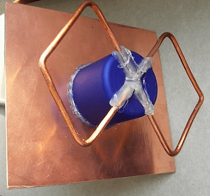
Harchenko antenna for modem
Currently, many users are striving to increase the speed of their mobile Internet. This problem is especially acute for those who live at a considerable distance from the base station, using the Internet at a very low speed. In such situations, the best way out is the Kharchenko antenna for a 3g modem with your own hands, which is quite easy to make at home.
This frame structure has been known as the UHF antenna since the 60s of the last century. It has a zigzag frame configuration, which makes the device very efficient.
The system consists of two square elements. In order to calculate the antenna for a 3g modem at a frequency of 2100 MHz, the size of each side of the square should be 53 mm. The whole structure is made in the form of an interlocked structure, which includes two diamond-shaped figures with internal angles of 1200. This is done in order to reduce the internal resistance of the device. The connection of rhombuses is carried out by soldering. The high-frequency cable is also soldered here.
More accurate data can be obtained using the online calculator for calculating the Kharchenko antenna, in which you just need to enter the necessary initial data.
To increase efficiency, the device can be used in conjunction with a reflector. Usually this part is a metal plate, and foil textolite is the most suitable material for its manufacture. In this case, the antenna includes determining the distance between the receiver and the reflector. After calculations and procurement of materials, a do-it-yourself Kharchenko antenna for the modem can be made.
The parts are connected to each other with the help of hot glue. You can fix the desired distance between the elements using any object with the most suitable dimensions. Then the antenna is connected to the device. Since the modems do not have connectors for connecting external antennas, they are simply wrapped with wire, which is then connected via a cable to the receiving device. If necessary, the Kharchenko antenna for a 4g modem can be made according to the same scheme.
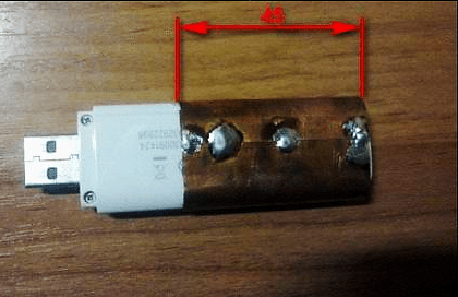
Upon completion of the assembly, at the opposite end of the cable that will be connected to the modem, you need to assemble the so-called matching device, which is provided specifically for such devices. For this purpose, copper foil is used, the same as in printed circuit boards. The performed antenna calculation for a 4g modem is the same as in the previous version.
If there is a connector for an external antenna, the cable is connected using a special adapter. After all connections, the antenna for the modem is considered ready for use. Setting the signal reception for 4g is carried out experimentally, by slowly rotating the structure around the axis until the clearest signal is obtained. Signal quality is determined by the number of dashes on the icon displayed on the computer or mobile phone.
Antenna Kharchenko for digital TV
For the operation of digital television, a range of decimeter waves is used. Therefore, before designing, Kharchenko antennas for DVB t2 should be made in order to maximize signal reception.
The design itself looks quite compact, it is made in the classic version of two rhombuses, as a result, a zigzag antenna without a reflector is obtained. Any conductive material can be used as a base, for example, a copper or aluminum conductor with a diameter of 1-5 mm. Tubes, strips, corners, profiles, etc. are also suitable. Copper wire 3 mm thick is best suited for these purposes. It is very easy to bend, level and solder. Further, it must be made in a certain sequence. TV cable resistance should be approximately 50-75 ohms.

The quality of a digital signal does not depend on distance, as it happens in analog television. In this case, when the TV antenna is working normally, the signal normally enters the TV receiver, but if there are failures, then there will be no signal at all. Accordingly, there will be no image. If there is a signal and it is normally received, then the image will be of the same quality on all channels. This factor must be taken into account when performing for digital TV, although individual settings may be different for a particular region.
Kharchenko's television antenna itself is made in a certain sequence:
- First you need to measure a piece of wire with a total length of 112 cm and bend it, observing the dimensions of the sections alternately 13 and 14 cm.
- After all the bends, two ends are formed, which must be cleaned to a distance of 1.5-2 cm. Loops are made at the ends and fixed to each other. The joints are completely soldered. Then, the central core is soldered to one of the joints, and the braid to the other. The result is a finished antenna or a double square.
- A biquad TV antenna requires a TV cable of approximately 3 meters. From the side of the antenna, it is stripped by 2 cm, and from the side of the plug - by 1 cm. The plug can be chosen at your discretion. It, like the wire, needs to be cleaned with a needle file or some kind of sharp object. Thus, Kharchenko's zigzag antenna for digital TV is almost ready for use.
- After soldering, all joints should be filled with hot glue from a gun. While the glue has not cooled down, its excess must be collected. It turns out at the same time reliable and elastic connection. On the antenna itself, the soldering points are also filled with glue.
Kharchenko antenna for phone
An external directional antenna can significantly increase the capabilities of a mobile phone and improve the quality of communication when a subscriber is in a remote area. It is not always possible to find the most suitable option on sale, so the best way out is the Kharchenko antenna for cellular communications, made from improvised materials with your own hands.

The most affordable option is the standard design discussed above. Such an antenna should be sized according to the specific operating conditions. All necessary materials are sold in the hardware store. The simplest designs can be directly connected to the cable and do not require any special settings.
First of all, it is necessary to stock up on copper wire, with a diameter of 2-3 mm. You can take an insulated wire and remove the insulation from it. If connections are to be made without soldering, special F-type antenna connectors and connectors will be required. When it is planned to connect two Kharchenko antennas in parallel, you may need a reflector, which can be tin or aluminum. Joints are insulated with heat shrink tubing or electrical tape. Soldering requires a soldering iron.
Copper wire, prepared in advance, is bent and turns into a zigzag frame, which is two rhombuses. The sides of each of them are 80 cm long, and the total distance between opposite corners will be 226 cm. Next, the antenna calculator determines the connection point of these diamonds as the junction with the cable. A piece of cable, 50 cm in size, is soldered to this point, and an F-type connector is screwed to its opposite end. Next, the main cable of the required length is connected to the connector.

In some cases, the calculation of the Kharchenko antenna online involves the installation of a reflector that significantly enhances signal reception in a certain area. The design is the same as the antenna for T2, when the lower end of the frame and the reflector are connected to each other through the cable braid. For this purpose, a bolt 50 mm long is additionally screwed into the reflector, to which an F-type connector is attracted with a tie. Beforehand, a cable and a frame located at a distance of more than 40 mm are soldered to this connector. Thus, the Kharchenko antenna for a mobile phone, made independently in the simplest version, is ready for use.
For direct connection of the receiving device with a mobile phone, a pigtail is used, which is a special wire. One end is connected to the antenna cable, and the other end is connected to the phone's antenna jack using a connector. In this case, there is no problem to calculate the antenna and no separate settings are required, it is enough just to position the antenna in the most optimal way, focusing on the quality of the received signal. It is recommended to install the mast with the receiving device as close to the house as possible, preferably near the window, in order to minimize the length of the cable.


