Dynamic heads.
The project under consideration was based on the use of a dome midrange VIFA D75MX-41-08, the main properties of which were determined by technical Project compromises in terms of choosing the remaining dynamic heads are approx.
The essence of the compromise is as follows. On the one hand, the main The advantages of the D75 dynamic head are a high acceleration factor (1420) and a low voice coil inductance (0.13 mH at a frequency of 10 kHz). On the other hand, the linear section of the voice coil stroke is 0.5 mm and the resonant frequency of 300 Hz excludes the possibility of using this head with a crossover frequency below 600 Hz. In this regard, part of the mid-frequency range must be reproduced by the bass head. For detailed reproduction in the frequency band up to 600 Hz, you will need a woofer with an acceleration factor of at least 300. This value of the acceleration factor of the woofer conflicts with the ability to provide a low cutoff frequency and a high sound pressure level at low frequencies. Options for a compromise resolution of this contradiction will be determined by the properties of the LF head.
The woofer head must satisfy one more requirement: it is desirable that its diffuser does not have noticeably pronounced resonance phenomena at operating frequencies, i.e. up to 600 Hz. It is difficult to determine compliance with the latest requirement based on studying the manufacturers' reference materials; you will have to purchase heads and take measurements. Table 1 shows the parameters of four LF heads with a diameter of 200 mm with an acceleration factor exceeding 300. Using reference data, the cutoff frequencies F3 are calculated for a volume Vb = 40 liters. For SEAS H1288 it is assumed to use a closed volume, for the remaining heads - a bass reflex.
Table 1.
|
Manufacturer, model |
BL/m |
SENS |
Xmax |
|||||
|
SEAS H1288 |
89.5 |
0.41 |
||||||
|
PEERLESS 830884 |
89.3 |
32.4 |
68.8 |
0.38 |
||||
|
BEYMA 8woofer/P |
0.38 |
|||||||
|
AUDAX HM210Z12 |
90.7 |
86.3 |
0.33 |
Of the four head models listed in the table, we were able to purchase three: H1288, 8woofer/P and HM210Z12. Figure 1 shows the Z-x characteristics of dynamic heads measured by LMS in current generator mode. The SEAS H1288 cone resonates at 680 Hz (blue curve). The BEYMA 8woofer/p diffuser resonates at a frequency of 500Hz (black curve). Z-characteristic of AUDAX HM210Z12 (yellow curve) does not show obvious resonance phenomena. Of the three available models of dynamic heads, the AUDAX HM210Z12 satisfies the requirements of the dynamics project to the greatest extent. The purchased BEYMA 8woofer/P speakers turned out to be unsuitable for further use in the project - their resonant frequencies and Qts values differed too much from those stated in the reference data.
For further work on the project, SEAS H1288 and AUDAX HM210Z12 remained. The H1288 loudspeaker was examined using a mock-up 40 liter cabinet, as this head is available for purchase by amateurs, in addition, it has some advantages over the HM210Z12 in terms of low-frequency reproduction. Listening to the loudspeaker prototype showed that the H1288, when used together with the D75, gives a satisfactory result, but discerning listeners on vocal parts noticed some coloration in the sound associated with the resonance of the diffuser at a frequency of 600 Hz. The copies of the H1288 heads used in the project had a total quality factor of 0.78 in a closed 40-liter case. For better reproduction of low frequencies, it was necessary to increase the volume of the case to 50 liters.
Figure 2 shows the speaker crossover circuit on the H1288.

Figure 3 shows the frequency response of the loudspeaker measured by a microphone located along the axis of the high-frequency head at a distance of 1 m.

The final version of the loudspeaker uses HM210Z12, which has more acceptable characteristics for reproducing vocals, since its diffuser does not have pronounced resonance phenomena.
The choice of a high-frequency driver to work with the D 75 is not determined by specific requirements, and the MOREL MDT 33 seems to be a completely acceptable option for a loudspeaker of this class.
Housing design.
A drawing of the speaker enclosure using the HM210Z12 is shown in Figure 4 4.

Preliminary calculations showed that the acoustic design of the HM210Z12 requires a volume of 40 liters with a bass reflex tuned to a frequency of 44 Hz. A pipe with an internal diameter of 75 mm and a length of 30 mm provided the specified tuning frequency. The hole for the pipe is located on the rear wall at the top of the case.
In a housing 1 m high, there is a need to suppress a standing wave between the upper and lower walls at a frequency of approximately 150 Hz. For this purpose, the hole in the jumper located below the woofer head is covered with synthetic padding, the volume of the housing under the jumper is filled with batting. The inner surface of the body above the lintel is covered with thin batting. The measures taken turned out to be sufficient to effectively suppress the standing wave, while having little effect on the efficiency of the bass reflex.
As an acoustic design for the mid-frequency head, a hemispherical chamber VISATON AK 10.13 is used, covered on the outside with guerlain and filled with synthetic padding. The camera and midrange head are installed on opposite sides of the front panel. This solution reduces the transmission of head vibration to the camera, which is essential for high-quality reproduction of mid frequencies, but leads to the need to make the back wall removable. The back wall is attached with ten self-tapping screws to frames glued into the body. Sealing of the rear wall is ensured by a polyethylene foam seal. The complexity of the housing design associated with a removable rear wall can be avoided by fixing and sealing the chamber with wires on the front panel before assembling the housing. For a loudspeaker with an H1288 low-frequency driver, you can use a housing of a similar design, increasing its depth to 300 mm.
TO rossover.
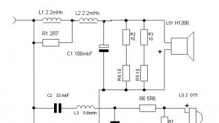
The crossover circuit is shown in Fig. 5

The crossover frequencies of 600 and 3500 Hz are selected in the loudspeaker. In the region of joint radiation of the low-frequency and mid-frequency heads, the second-order Butterworth sound pressure drops in the frequency response are summed up, requiring antiphase switching on of the dynamic heads. The correction chain R1L1 serves to compensate for the rise in frequency response associated with the transition of the low-frequency head's radiation mode from space to half-space. Resistors connected in parallel with the low-frequency head reduce unwanted interaction of the low-frequency head with the filter. (This issue is discussed in detail in the work “Amateur Loudspeakers 3”). Capacitance C2 protects the midrange head from overload with low frequencies and forms a specified decline in the frequency response of the head in the lower region of joint radiation.
In the region of joint radiation of the midrange and high-frequency heads, fourth-order Linkwitz-Riley sound pressure frequency response decays are used, obtained using second-order electrical filters. The transfer characteristics of crossover filters are shown in Fig. 6. The crossover uses MUNDORF, VISATON and SOLEN elements.

Figure 7 shows the frequency response of dynamic heads working with filters. Figure 8 shows the frequency response of the loudspeaker, measured along the axis of the HF head at a distance of 1 m. Figure 9 shows the frequency dependence of the loudspeaker impedance.


Conclusion.
Experience with this project shows the possibility of obtaining sufficiently high-quality reproduction of phonograms of vocal parts through the use of a VIFAD75 dome midrange driver. Considering that it is difficult to reproduce a loudspeaker using HM210Z12 due to the lack of these heads on sale, with some reduction in the requirements for reproduction of mid frequencies, you can use the H1288 .
An interesting article in Radio magazine, issue 10, 1983. Loudspeaker with increased efficiency Section Sound reproduction.
In accordance with GOST 24307-80 (Article CMEA 1356-75) and the DIN 45500 standard for high-fidelity loudspeakers of the Hi-Fi category, the so-called operating power is additionally indicated (power creating a nominal sound pressure of 1.2 Pa or 96 dB at a distance 1m). This parameter is not specified by chance: it, in essence, determines the efficiency of the loudspeaker (lower operating power corresponds to higher efficiency) and the level at which the harmonic distortion is measured. The lower the operating power of the loudspeaker compared to the nominal one, the easier the listener will use it. All this has a beneficial effect on sound quality, since it is known that when the head operates with a power two to four times less than the nominal one, the nonlinear distortions of the signal it reproduces are almost halved. Loudspeakers with increased efficiency due to a higher maximum reproducible level have a wider dynamic range and greater overload capacity for pulsed signals at low and medium volume levels.
The efficiency of industrial and amateur loudspeakers intended for use in high-quality household radio equipment is relatively low. This is evidenced by the operating power, which, for example, for such widespread loudspeakers as 35AC-1 and 25AC-2 (25AC-9, 25AC-326) is 16 W, which is 0.45 and 0.64 of their rated power, respectively. .
The loudspeaker, the description of which is brought to the attention of readers, has increased efficiency and overload capacity (its operating power is 0.16 of the nominal), a wide dynamic range and a fairly uniform frequency response compared to the above loudspeakers.
Main technical characteristics:
Rated power. W…………25
Maximum power. W………35
Nominal electrical resistance, Ohm…. 8
Efficiently repeatable range
frequencies, Hz, with uneven frequency response 12 dB………….35 - 22,000
Average standard sound pressure, Pa……….0.2
Operating power, W, no more than…………….4
Filter crossover frequencies, Hz……………….500 and 5000
Dimensions, mm, (height x width x depth):
without HF head unit…………….740x400x385
with HF head unit…………….936 x 400X 475
Judging by the literature, not all experts believe that the use of crossover filters with a linear phase response for Hi-Fi loudspeakers is mandatory. This follows from the statement that the maximum value of the group delay can reach 2 ms, from which it follows that a filter of any first to third order meets these requirements. From this we can conclude that the linearity of the phase response of the crossover filter is not very important for amateur designs. At the same time, as will be shown below, it seems to the author that it is essential to maintain the linearity of the phase of the heads when installing them in a loudspeaker housing.
The connection diagram for loudspeaker heads and crossover filters is shown in Fig. 1. In order to improve the band separation, combined crossover filters C2L2C4 (C3L4C6) and C1L1L3C5 with different slopes of the frequency response (18 and 12 dB per octave, respectively) were used. At the crossover frequency of the low-frequency and mid-frequency sections, for the purpose of carrying out experiments, switch S1 can turn on the first-order filter C1L1 with an amplitude-frequency response slope of 6 dB per octave, which has a greater linearity of the phase response. The filter order is set by the listener depending on the desired sound character.
This loudspeaker provides the ability to rephase the heads of each band using switches S2 - S4. The initial position is considered to be the position in which the midrange heads are turned on in antiphase with respect to the low-frequency and high-frequency ones. Filter coils L1 and L2 are wound on frames made of insulating material with a diameter of 60 mm, the winding is ordinary, its length is 30 mm, the diameter of the cheeks is 100 mm. The first coil contains 196, and the second - 235 turns of PEV-2 1.84 wire. Reels L3 and L4 are made on frames with a diameter of 24 mm, winding length 12 mm, cheek diameter 54 mm. Coil L3 contains 115, and L4 - 98.5 turns of PEV-2 1.12 wire.
The heads are bypassed with corrective RC circuits. As a result, due to more complete matching of the heads with the crossover filters, harmonic and intermodulation distortions were reduced and the linearity of the frequency response was improved. The loudspeaker also includes attenuators that allow you to adjust the frequency response of the midrange link within ±4 dB, and the HF link within +6...-2 dB relative to the level shown on the tab.
The loudspeaker is made in the form of a bass reflex. The low-frequency heads are fixed on the outside of the front panel 1 in the recesses selected with a chisel, so that their diffuser holders are placed flush with the panel. The inner side of the holes for the woofer head was chamfered at an angle of 45° to a depth of 10 mm.
Panel 4, on which the mid-frequency heads are installed, is made of aluminum with a thickness of 3 mm (you can use vinyl plastic, organic glass or polystyrene with a thickness of 3.5 ... 5 mm). In front of these heads, on the front panel there is a decorative frame made of steel wire with a diameter of 4 mm, and a nylon mesh (fabric, canvas, etc.) is stretched over it. An L-shaped partition (parts 2, 3) made of 10 mm thick plywood is installed on the back side of the midrange heads, separating them from the internal volume of the loudspeaker body.
The panel of high-frequency heads is made of aluminum with a thickness of 2 mm. To eliminate phase shift due to the placement of the acoustic centers of the mid-frequency and high-frequency heads in different planes, the high-frequency link is made in the form of a separate unit, consisting of four 2GD-36 heads loaded with exponential matching horns. Within an angle of 90...95° (i.e. ±45° from the axis of the head) there is no noticeable decrease in the sound pressure of the high-frequency unit. It is possible to move the block in depth in order to obtain the best spatial linearity of the phase characteristics of mid- and high-frequency heads. The axes of the mid-frequency drivers are also rotated (at an angle of 25°), which helps to expand their directional pattern and obtain a wider stereo effect area. There is no need to take special measures to improve the linearity of the phase response of the loudspeaker at the crossover frequency of mid- and low-frequency drivers, since the possible displacement of the acoustic centers of these links by 7...15 mm is much less than the wavelength at the crossover frequency (0.68 m at a frequency of 500 Hz) and the introduced As a result, the phase shift is very small.
The speaker housing is made of 20 mm thick chipboard. The back wall of the case is removable. To fill the internal volume of the case you will need 1300... 1400 g of cotton wool.
To prevent chipping of the edges of the front panel, it is advisable to make it from plywood 20 mm thick or from chipboard veneered on both sides. If, however, non-veneered chipboard is used to make the front panel, it should be placed on the walls of the case, and not inserted inside it. This will increase the distance of the heads to the edges of the front panel and prevent possible chipboard chipping.
The described loudspeaker uses a bass reflex tunnel of variable cross-section. Compared to tunnels of constant cross-section (cylindrical and rectangular), it has better transient characteristics at a shallower depth and does not create extraneous sounds or resonance phenomena inside the pipe.
The tunnel is tuned to a frequency of 37 Hz. It is made of plywood (you can getinaks) 8 mm thick in the form of a truncated pyramid with a lower base measuring 80x130 mm, a top 80x80 mm and a height of 70 mm (internal dimensions are indicated everywhere).
Ferrite-barium magnets of grade 2BA with a diameter of 74..85 mm are glued to the magnetic systems of low-frequency and mid-frequency heads using BF-2 glue. Such magnets are used in heads 4GD-8E, 4GD-36, 6GD-2, 6GD-6, 10GD-34 and the like. The main and additional magnets are oriented in such a way that they repel each other and stick together. After this, stamped caps with a diameter of 100 mm (the height depends on the thickness of the magnet being glued), made of steel St., are glued onto the additional magnets. 3 1.5 mm thick. For this song, although with a slightly worse effect, you can use metal cans of green peas (“Globe”).
The described modification of the heads made it possible to increase their nominal sound pressure by 15..25%, reduce the harmonic coefficient at low and medium signal levels, and improve the transient characteristics of the midrange heads.
To improve damping, the midrange driver diffusers are impregnated with castor oil.
As already indicated, high-frequency heads are installed at the mouths of exponential horns, the vertical section of which is shown in Fig. 4. The vertical walls of the horn are flat, the horizontal walls are curved. The dimensions of the wellhead are 53x36 mm, the outlet - 166x96, horn depth - 116 mm. The horn protrudes approximately 90 mm beyond the speaker housing. This distance is selected when listening to music programs.
The use of a horn improves the directivity characteristics and increases the sound pressure on the axis of the head by approximately 2 times (up to 0.4 - 0.45 Pa). As a result, the high-frequency unit, consisting of four 2GD-36 heads, turns out to be equivalent to a high-frequency head with a power of 50 W, an electrical resistance of 8 Ohms and an average standard sound pressure of 0 2 Pa. The loudspeaker can be used with various high-class industrial and amateur amplifiers with a rated power of 8...50 W.
A. Golunchikov


At the exhibition RosHI-End 2013, together with an amplifier by L. Zuev and a DAC by V. Korsakov, a three-way loudspeaker on speakers with metal diffusers was demonstrated. The reproduction of musical material selected by V. Lukhanin by this system has received many reviews, which can be found on the Vegalab website.
The development was carried out with the goal of constructing a compact floor-standing loudspeaker intended for sounding residential premises with an area of up to 15-20 square meters. meters, focused on playing music programs with a dense spectrum and high-quality vocal reproduction against the backdrop of a dense signal spectrum. Below we will consider a version of this loudspeaker, modified based on comments from visitors and exhibitors, as well as taking into account the possibility of repeating the design at home. The increase in the project budget associated with the modification seems to us justified by the increase in the quality of sound reproduction. Below we will talk in more detail about compromises, including between price and quality.
In residential premises with an area of 15 -20 sq. m. It is not always possible to optimally place speakers, which leads to problems in reproducing low frequencies and deterioration in the localization of apparent sound sources. This circumstance was taken into account and was reflected in the choice of the main technical solutions of the project.
A drawing of the loudspeaker enclosure is shown in pic 1.
 The front panel has a trapezoidal shape, the variable width of the front panel slightly reduces diffraction effects. The low-frequency closed-type acoustic design has a usable volume of 30 liters, which is powered by the RS225 speaker. Inside the low-frequency compartment there is a piece of sound absorber (sintepon) measuring 0.5 by 0.5 m. The choice of a closed acoustic design is due to the desire to obtain the most compact impulse response of the low-frequency section.
In residential premises, as a rule, there are standing waves between the walls, between the floor and the ceiling. In such a situation, it is advisable to favor a compact impulse response over extending the frequency range downward using a bass reflex.

 The midrange speakers operate on a closed volume of 6 liters, tightly filled with sound absorber. The use of two W4-1337SD speakers for the midrange leads to an increase in costs, which is justified by the improvement in overload capacity at mid frequencies and allows the construction of an MTM configuration that provides a narrowing of the radiation pattern in the vertical plane. Narrowing the radiation pattern in the midrange seems to be an additional bonus, since it increases the level of the direct signal at the listening point. A simulation of the radiation pattern in the vertical plane is shown in rice. 2. The W4-1337 speaker has a moving mass of 4.6 grams with a cone area of 57 square meters. cm, linear portion of the voice coil stroke is 3 mm. The voice coil inductance value of 0.015 mH indicated in the manufacturer's data sheet is questionable.
According to my estimates, W4-1337 has Levc = 0.4 mH, which is quite acceptable for mid frequencies. The low moving mass and rigid diffuser ensure good transmission of dynamic contrasts. This speaker is manufactured in two versions: W4-1337SD has a neodymium magnet, W4-1337SDF has a ferrite magnet. Both versions are suitable for the loudspeaker. Prior to the publication of this work, it was possible to examine 18 specimens of W4-1337SDF and 24 specimens of W4-1337SD. Based on the results of parameter measurements, it became clear that it was possible not to select speakers in pairs for the MTM configuration.
 The increase in the budget associated with replacing the Seas H1499 tweeter with a Mundorf AMT 19CM 2.1 is justified by an increase in the quality of high-frequency reproduction. In addition, as a result of the replacement, it was possible to exclude 4 elements from the filter circuit, including those requiring adjustment, since AMT 19CM are supplied in pairs, with a small spread of characteristics.
The choice of speakers for the loudspeaker assumed the use of crossover frequencies of 500 and 3500 Hz. The specified crossover frequencies with a margin ensure that the speakers operate in piston mode.
At a crossover frequency of 500Hz, the two-polar impulse response, which is inevitably obtained when the speakers are turned on in antiphase, does not spoil the sensation of sound perception. I assume that the waveform distortion lasts less than 2 ms. lie beyond the temporal resolution of hearing at frequencies above 500 Hz. A simulation of the impulse response of LF and MF speakers working with filters is shown in rice. 3. The result of the impulse response simulation raises some doubts; this issue will have to be sorted out. For now, you can focus on the listening results, which indicate fast and dynamic sound delivery in the low-frequency range.
The crossover frequency of 3500 Hz is an acceptable compromise due to non-linear distortion of the midrange and tweeters.

 The result of the loudspeaker frequency response simulation is shown in rice. 4. The frequency response has been optimized for a listening distance of 2.5 m. The slight increase at the upper edge of the frequency range takes into account the decrease in acoustic power with increasing frequency, which occurs due to a narrowing of the radiation pattern. On rice. 5 shows the phase response of speakers working with filters.
 The crossover circuit is shown in rice. 6. At a cutoff frequency of 500 Hz, the filters formed 2nd order frequency response slopes with a quality factor of about 0.5. The LF and MF speakers are switched on with reverse polarity. A wide co-emission region (Fig. 4) and a compact impulse response (Fig. 3) provide a cohesive and dynamic sound delivery. At the crossover frequency of 3500, 4th-order frequency response slopes according to Linkwitz-Reilly are formed. For the AMT 19CM 2.1 high-frequency speaker, the formation of a given frequency response decline was provided by a 2nd order electric filter; for the midrange speakers, a 3rd order electric filter was required.
The tweeter filter places the most stringent demands on the quality of the elements. The option of parallel connection of film and foil capacitors turned out to be a good compromise between price and quality.
The notch filter R5 L4 C5, which, according to a widespread myth, should kill sound, performs the function of protecting the midrange speakers from overload and corrects the phase response at a frequency near 100 Hz. The value of resistor R5 depends on the ohmic resistance of coil L4. The sum of the ohmic resistance of coil L4 should be 4 ohms ± 10%. When repeating a loudspeaker, it is not at all necessary to use the types of components that are indicated in the tables. Crossover filters have a low quality factor and allow deviations of values from those indicated in the diagram of at least 5%, and 10% in the ohmic resistance of the coils. The crossover uses 10 W MOX resistors.
Inductors
| L1 | Mundorf Aire Core M Coil | 0.47 mHn 0.58 Ohm |
| L2 | Mundorf Aire Core M Coil | 0.82 mHn 0.44 Ohm |
| L3 | Mundorf Aire Core M Coil | 0.22 mHn 0.21 Ohm |
| L4 | ERSE Air Coil ALg 20ga | 3.3 mHn 1.37 Ohm |
| L5 | Mundorf Ferrite M Coil BH Drum coil | 5.6 mHn 0.62 Ohm |
Capacitors
| C1-2 | Dayton Audio PPF | 0.47 mkF 400V |
| C1 | MKP Mundorf M Cap | 3.3 mkF 250V |
| C2 | MKP Mundorf M Cap | 22 mkF 400V |
| C3 | MKP Mundorf M Cap | 10 mkF 400V |
| C4 | MKP Mundorf M Cap | 8.2 mkf 250V |
| C5 | Erse Non-Polarized | 470 mkF 100 V |
| C6 | MKP Mundorf M Cap | 47 mkF 400V |
 On rice. 8 shows the frequency dependence of the input impedance of the loudspeaker. The minimum input resistance is 6 ohms, the maximum is 13.5 ohms. The phase angle, which characterizes the reactive component of the input resistance, does not go beyond plus - minus 30 degrees in the frequency band 20 - 20000 Hz. The parameters of the input impedance of the loudspeaker allow us to consider it a quite comfortable load for the amplifier.
 The transfer characteristics of the filters are shown in rice. 7. Resistor R6 with a value of 22 Ohms was sufficient to eliminate unwanted interaction between the filter and the speaker. This can be judged by the transfer characteristic of the low-pass filter. “Pumping” does not exceed 1.5 dB with a maximum at 70 Hz.
 On rice. 9 shows the loudspeaker's frequency response, measured in a room at a distance of 1 m at an input voltage of 2.83 V. The measured frequency response is not smoothed, but is the result of averaging three measurements: along the axis of the tweeter and when the microphone is shifted 5 cm down and up from the axis. This measurement technique allows you to get a clearer idea of the tonal balance of a loudspeaker in a room than a smoothed frequency response along the axis of the tweeter.
In conclusion, I consider it necessary to express gratitude to V. Lukhanin, who resolved all organizational issues and carried out the bulk of the work on modernizing the loudspeaker, to the Difton company, which quickly and efficiently manufactured the enclosures, as well as to all sound lovers for their comments and suggestions on the project.
Improving the sound quality of modern loudspeakers is achieved mainly through the use of new powerful dynamic drivers, and this most often entails an increase in their dimensions, weight, and cost. Meanwhile, a very good loudspeaker can be built on the basis of inexpensive dynamic heads.
Main technical characteristics.
Rated (nameplate) power, W....................................10 (30)
Nominal range of reproduced frequencies, Hz............30...25,000
Number of lanes................................................... ........................................3
Section frequencies, Hz................................................... ....................500; 5000
Nominal electrical resistance, Ohm............................6.3
Average standard sound pressure, Pa...................................0.35
Dimensions, mm................................................... ................................620x350x310
The electrical circuit of the loudspeaker is shown in Fig. 1. It is built on the basis of three dynamic heads. The low-frequency (LF) functions are performed by the 6GD-2 head, the mid-frequency (MF) head - 3GD-38E, and the high-frequency (HF) head - 6GD-13 (new name 6GDV-4). The second-order filter L1C1 is used in the low-frequency section, the first-order filter L2C2 is used in the midrange, and the third-order filter L3C3C4 is used in the high-frequency section. To equalize the frequency response of the loudspeaker in the region of medium sound frequencies, the midrange head is connected through resistor R1. In order to improve the sound of the system at frequencies above 503 Hz, the 6GDV-4 HF head is connected to a filter using resistors R2 and R3. It is important to note that this head is turned on in antiphase with the bass and midrange heads.
Fig.1. Electrical circuit of a three-way loudspeaker filter
The acoustic design of the loudspeaker is a bass reflex. Its body is made of chipboard 20 mm thick. The front panel and side walls are connected to each other with 20 x 20 mm slats using EDP epoxy glue. The back wall is removable; it is attached to the body through 2 mm thick rubber gaskets.
The view from the front panel is shown in Fig. 2, a, and a section of the body along line A-A- in Fig. 2, b. The bass and midrange speakers are attached to the outside of the front panel. Between it and the head diffusers there are rubber (polyurethane foam) rings 1.5 mm thick are laid.

Fig.2. Three-way loudspeaker drawing
Before placement on the front panel, the 6GD-2 head must be modified in order to reduce its overall quality factor. To do this, acoustic resistance panels (ARPs) should be installed in the windows of its diffuser holder, i.e., sealed with synthetic felt or, in extreme cases, medical gauze folded in several layers. The mid-frequency head must be placed in a sealed box with a volume of about 2 liters, filled with cotton wool. The diameter of the box is equal to the diameter of the hole in the front panel for the midrange head. The place where it connects to the panel must be carefully sealed (for example, with plasticine). The 6GDV-4 RF head is mounted on the inside of the front panel, and the side surfaces of the hole for its installation should, as it were, continue the cone existing on the head and form a radiating horn with it. A sealing rubber ring should be placed between the body of this head and the panel. The bass reflex tunnel is a plastic tube with an outer diameter of 70 and an inner diameter of 65 and a length of 150 mm. It is inserted into the corresponding hole on the front panel from the outside. The gaps between the panel and the tunnel are sealed from the inside with plasticine.
The crossover filter parts are placed on a getinax board measuring 250 x 150 mm, installed on the side wall of the housing in its lower corner, opposite the bass reflex tunnel. To avoid rattling, a sound-absorbing gasket must be laid between the board and the case. The filter uses non-polar MBM capacitors. MBGO for a voltage of 200 V and wirewound resistors with a power of 2 (R3) and at least 7.5 W (others). Capacitor C1 is made up of six 10 micron capacitors connected in parallel. Coils L1-L3 are frameless. The internal diameter and height of the first of them is 40 mm, the other two are 25 and 30 mm, respectively. Coil L1 contains 260 turns of PEL 1.5 wire, L2-170 and L3-90 turns of PEV 1.0 wire. The inner surface of the case is covered with sound-absorbing material (batting, foam rubber) with a thickness of 10...15 mm. The body itself is filled with cotton wool, but in such a way that an air passage is left between the woofer head and the bass reflex. All connections of the housing walls are sealed with epoxy glue.
The sound of the described loudspeaker was compared with the sound of the well-known industrial model 35AC-012 (S-90). During the tests, a stereo AF amplifier with a rated power of 2 x 25 W and a harmonic coefficient of no more than 0.2% was used. The softer sound of the homemade loudspeaker was noted in the region of low and medium sound frequencies, as well as the absence of unpleasant overtones created by the 10GD-35 head installed in the 35AS-012 in the range of 5...10 kHz.
P.S. Replacing the 6GD-2 head. Instead of 6GD-2, you can use a dynamic head 75GDN-1L-4 (formerly designated 30GD-2) or 35GDN-4 (25GD-26B). These heads have more than half the standard sound pressure (0.15 and 0.12 Pa, respectively) compared to the 6GD-2 (0.35 Pa), but their significantly higher rated power compensates for this disadvantage. The nameplate power of the loudspeaker after such a replacement will increase in the first case to 50, in the second - to 40 W, the nominal electrical resistance will drop to 4 Ohms. The capacitance of capacitor C1 when using the 75GDN-1L-4 head is 80 µF. PAS is not required in both cases. The first replacement option is preferable, since the 75GDN-1 L-4 head has the same dimensions as the 6GDN-2, and greater efficiency than the 35GDN-4, especially at frequencies below 100 Hz.Yu. DLI, Gorky
Radio magazine, No. 3.9 1989
A three-way dividing line with a crossover frequency of 520–4800 Hz was used (Fig. 1). The presence of attenuators allows you to adjust the frequency response of the loudspeaker in the mid-high frequency region by ±4 dB relative to the average (zero) level. The attenuator resistors are made of Provo-PEMS 0.41 - 0.56. They can be made from iron-tiles.
Separating coils. filters are wound on frames made of wood (birch, ) with. external 0 36 mm, length 24 mm (Fig. 2), and contain: LI, L2 - 260 turns each, L3 - 85 turns, L4 - 170 turns with a tap from the middle of the PEL 1.0 wire.
The loudspeaker body and front panel are made of 16 mm thick chipboard (Fig. 3). The front one (Fig. 4) is deepened by 20 mm. The back cover of the speaker is secured with overlapping screws. Between the back cover and the case for sealing, feathery rubber 5 mm thick is laid. The boxes are fastened with birch bars, pre-coated with EDP-3 or EDP-5 glue. glue seals the loudspeaker.
The dynamic heads are installed on the front side of the front panel. For this purpose, recesses are made in the frame of the dynamic heads. Between the front panel and the bars, and to which it is attached, porous rubber is laid for sealing. Then inside the box, seals are created from cotton wool at an angle so that it becomes spherical. The mid-frequency one is covered with a cap made according to the same technology: a cylindrical blank 0 140 mm, 120 mm high, is machined from foam plastic. Then with one it is given a spherical shape (Fig. 5). A thin (1 - 2 mm) amount of plasticine is carefully applied to the surface of the finished sphere. Then, using the papier-Mrshe method, pieces of fiberglass impregnated with EDP-3, EDP-S glue, 2 - 3 mm thick, are glued onto it. After the glue has dried, the sphere is removed from the foam plastic blank - the cap for the frequency head is ready. The windows of its frame are sealed with mar- , the volume between the head and the cap is evenly filled with cotton wool.
MAIN TECHNICAL DATA:
effectively reproduced frequencies (Hz) with unevenness of 14 dB - 20 - 25000,
with unevenness 8 dB - 20 - 22,000;
dimensions, mm - 460X350X260.

Rice. 1. Schematic diagram of a separating filter.


An air passage is formed between the low-frequency head and the phase inverter using a metal mesh. The remaining volume of the box is evenly filled with cotton wool weighing 0.9 - 1.5 kg. The phase inverter consists of a glass and a pipe insert (Fig. C, made of -16T duralumin. They can also be made using the method from fiberglass and ZDP-3 glue.

Rice. 6. Bass reflex: 1 - glass, 2 - insert.