There are many articles on the Internet about how to make your own TV remote control on Arduino, but I needed a universal remote control for TV and media player. The main advantage of my universal remote is that the buttons in the application for android phone are dual-purpose, but by the way, look at the video.
The remote control is very convenient in that almost the same buttons on the screen are used to control the TV and the player. One difference is that the " AV" in TV control mode changes to " ◻
" (stop) when switching to the player control mode. The pictures show two modes, on the left is the TV control mode, on the right is the player control mode.

Well, now I will tell you a little about the creation of such a remote control. For the device, I used the ERGO TV remote control and the DUNE HD TV101W media player remote control.

To receive data from the remotes, I used the TSOP1138 infrared sensor (analogous to TSOP4838) at an operating frequency of 38 kHz and connected it to the Arduino board according to the scheme:


This sketch will not be required to determine the data transfer encoding and read the code for the remote control buttons.
In the sketch, in the line int RECV_PIN = 11; we indicate our pin at number 4
After uploading the sketch, open the “port monitor” and, by pressing the remote control buttons, look at the received data.

The picture shows an example of scanning the power button from the TV remote control and the player remote control. Now we form a table for button codes.

I got it like the photo above. Under the inscription TV TV remote control button codes under the inscription Player- codes from the media player remote control.
Now we disconnect our infrared signal receiver from the Arduino board and connect the HC-05 Bluetooth module and an infrared LED to it according to the diagram in the photo.

After that, we go directly to the sketch.
Sketch
#include
In the sketch, you will need to edit the button codes, namely in the lines:
If (x == 97) ( irsend.sendNEC(0x807F08F7, 32); delay(40);
Change the value of 807F08F7 to:
If (y == 1) ( //button codes for the TV remote control if (x == 97) ( irsend.sendNEC(0x12345678, 32); delay(40); )
Where 12345678 is the code for your button.
After editing the sketch according to your button codes, upload the sketch to the Arduino board and proceed to install the application on your phone.
We turn on the bluetooth in the phone, search for our device, create a pair, then launch the application Console on the phone.
When launched, we will have a screen with a red bluetooth icon in the lower right corner, which signals that we are not connected to our device.

Then click on this icon. We should have a window with a list of all available bluetooth devices, where we select our device to connect.

Now we are back on the main screen and we can already control the TV:
To switch to control mode, we need to press the button labeled "Player". As I said before, we have a button labeled "AV" will change to a button " ◻ ":
To disconnect from our device, simply hold down the "Power" button for a few seconds.
Well, a few photos of my finished device.


It turned out, it seems, well. I look forward to comments on the article.
IR receiver and infrared remote control is the most common and easiest way to control electronic equipment. The infrared spectrum of radiation is not visible to the human eye, but it is perfectly received by IR receivers that are built into electronic devices. Arduino ir remote modules are used to control various equipment in line of sight.
The widespread use of IR emitters has become possible due to their low cost, simplicity and ease of use. IR radiation lies in the range from 750 to 1000 microns - this is the closest part of the spectrum to visible light. In the infrared region, the optical properties of various materials can change. Some glasses, for example, become opaque to IR rays, while paraffin, on the contrary, is transparent in the IR spectrum.
The radiation is registered with the help of special photographic materials, on the basis of which the receivers are made. In addition to heated bodies (the Sun, incandescent lamps or candles), the source of infrared radiation can be solid-state devices - IR LEDs, lasers. Radiation in the infrared range has a number of features, thanks to which it is convenient to use them in remote controls:
- Solid state emitters (IR LEDs) are cheap and compact.
- Infrared rays are not perceived and are not fixed by the human eye.
- IR receivers are also cheap and small in size.
- Little interference, since the transmitter and receiver are tuned to the same frequency.
- There is no negative impact on human health.
- High reflectivity on most materials.
- IR emitters do not affect the operation of other devices.
 The remote control works as follows. When the button is pressed, the signal is encoded in infrared light, the receiver receives it and performs the required action. Information is encoded as a logical sequence of bursts of pulses with a certain frequency. The receiver receives this sequence and demodulates the data. To receive a signal, a microcircuit is used, which contains a photodetector (photodiode), amplifiers, a bandpass filter, a demodulator (a detector that allows you to select the signal envelope) and an output transistor. It also has filters - electrical and optical. Such devices work at a distance of up to 40 meters. IR method of data transmission exists in many devices: household appliances, industrial equipment, computers, fiber optic lines.
Arduino IR receiver
To read the IR signal, you will need the Arduino board itself, a breadboard, an IR signal receiver and jumpers. There are a huge number of different receivers, but it is better to use TSOP312 or other suitable ones for Arduino. Data from the remote control to the receiver can be transmitted using the RC5 or NEC protocol.
To determine which leg belongs to what, you need to look at the sensor from the side of the receiver. Then on the receiver the central contact is the ground, on the left is the output to the microcontroller, on the right is the power supply.


For convenience, you can use ready-made IR receiver modules.


Connecting IR receiver to arduino
The outputs of the IR receiver are connected to the Arduino to the GND, 5V and digital input ports. The diagram for connecting the sensor to digital pin 11 is shown below.
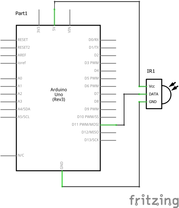
This is how the circuit with the infrared receiver module looks like:

Libraries for working with IR
To work with IR devices, you can use the IRremote library, which simplifies the construction of control systems. You can download the library. Once downloaded, copy the files to the \arduino\libraries folder. To connect to your library sketch, you need to add the header file #include
To read the information, use the IRrecvDumpV2 example from the library. If the remote control already exists in the list of recognized ones, then scanning is not required. To read the codes, you need to launch the ARduino IDE and open the IRrecvDemo example from IRremote.
There is also a second library for working with IR signals - this is IRLib . It is similar in its functionality to the previous one. Compared to IRremote, IRLib has an example for determining the frequency of an IR sensor. But the first library is easier and more convenient to use.
After loading the library, you can start reading the received signals. The following code is used for this.
The decode_results operator is needed in order to assign the received signal the name of the results variable.
In the code, you need to rewrite "HEX" to "DEC".
Then, after loading the program, you need to open the serial monitor and press the buttons on the remote. Various codes will appear on the screen. It is necessary to make a note with which button the received code corresponds to. It is more convenient to record the obtained data in a table. After this code can be written into the program so that you can control the device. The codes are written to the memory of the Arduino board itself EEPROM, which is very convenient, since you do not have to program the buttons every time you turn on the remote control.
It happens that when loading a program, an error “TDK2 was not declared In his scope” is generated. To fix it, you need to go to the explorer, go to the folder where the Arduino IDE application is installed and delete the IRremoteTools.cpp and IRremoteTools.h files. After that, you need to reload the program on the microcontroller.
Conclusion
Using the Arduino ir remote makes life easier for the user. A mobile phone, tablet or computer can act as a remote control - this only requires special software. With the help of Arduino, you can centralize all control. With one button on the remote control, you can perform several actions at once - for example, turn on the TV and Blu-Ray at the same time.
When creating devices for working with IR remotes, a tool is very necessary with which one could record and analyze IR signals. Such an instrument, ideally, could be a digital oscilloscope or a logic analyzer, but not everyone has these devices, and it is expensive to buy specially. How to be? There is a very simple solution - a computer sound card! We will record the signal with its help.
In addition to the sound card (which I hope you have in your computer) we need an IR receiver. It would be more correct to assemble a full-fledged receiver circuit with TSOP, but let's do it as simply as possible - as an IR receiver, we will take the most ordinary IR LED (the one that is in your remote control). You can, of course, take an IR photodiode, but an IR LED is easier to get. The IR LED must be connected directly to the microphone input of the sound card. To do this, you need a 3.5mm plug and a piece of shielded wire (I cut off the cord with the connector from an old non-working microphone).
The LED is connected as follows:

As a result, we get the following device:

We insert the plug into the microphone input (it is pink). In the sound card settings, select the microphone as an input device, turn the gain control to the maximum and check the additional gain box. To check, we direct the remote control at the LED receiver (it is necessary to bring it as close as possible to the remote control), press the key - clicks should be heard in the speakers.

If for some reason you do not have a microphone input (for example, in a laptop) - connect the receiver to the line input of the sound card - everything will work the same, only the amplitude of the recorded signal will become much smaller.
Now we need a program to record sound. For these purposes, any program that you have is suitable. If you do not have a favorite program for working with sound, I suggest a small and free program - Wavosaur (http://www.wavosaur.com/) The program works without installation and has a small size - as I like :).
Sound program.
After starting the program, turn on the level indicator (the ruler on the right side of the window) and check the response to the remote control signals. By default, everything should work - the ruler will go off scale from the received signals (if there is no reaction, we climb into the settings Audio configuration/Audio in). Next, press the record icon, bring the remote control as close as possible to the receiving LED, press the remote control key and hold for a couple of seconds. Disable recording - Done! In the window we will see the scan of the received IR signal. Interestingly, the signal will already be detected - we will not see the carrier frequency, but only the useful signal. This is due to the fact that the input capacitances of the microphone input do not have time to recharge.
The received signal can be scaled in time, amplitude and, which is very convenient, by highlighting a certain interval, you can immediately see its duration. The received signal can be saved (preferably in wav format - there will be no distortion) or exported to MP3, text, binary file (a useful thing!).
For example, the signal from my TV remote control (NEC format):

The picture shows all the time intervals, you can even calculate the remote control address and the button command code - everything is clear and understandable.
P.S.
Big request! If you assemble such a receiver, save the parcels of your remotes and send them to me on the soap (in the tab "about the project") - this will greatly help in improving the algorithm of the universal receiver. In the file name, indicate from what the remote control and the manufacturer's company (for example: tv-sony.wav).
More about working with IR remotes!
I suggested the easiest option to "feel" the signal from the IR remote, but there are many solutions that can do much more! Receive an IR signal, analyze, save, reproduce, program your remotes, control a computer ... This section will contain links to such solutions.
1. DvzRcEditor
The program will go first DvzRcEditor, thrown off mobi. The program was made by Dvz 2010(unfortunately there is no coordinates, maybe someone knows?). 
- A program for analyzing and repeating IR signals.
The program allows using the microphone input and audio output to both record and play back IR messages. There are tools for analyzing IR-messages and creating a database of remotes sendings (there is a small database for various remotes). An interesting solution is to support your remote, made on ATtiny2313. 
The remote has 7 keys that can be set to any of the analyzed commands, and the program itself can write the signals for these buttons to the microcontroller (provided that you flash the bootloader there for the first time).
Everything is simple and clear - I liked it!
2.SlyControl.
http://slydiman.narod.ru/scr/index.htm
This is not even a program - this is a whole Internet resource dedicated to IR remotes. Contains a lot of useful information, hardware and software solutions for all occasions. Here is what the authors write about SlyControl:
is a universal program for managing anything with the help of a computer.
What it can be used for:
- control of any programs from any remote control (RC), from the multimedia keyboard with keys or joystick
- keyboard and mouse emulation from any remote control
- scheduler (not just run the program on time, but also perform some actions with it)
- shutdown the computer by timer or by event
- you can also turn on the light in the apartment with remote control, you just need to add the appropriate plugin 😉
And there is a program on the resource RCExplorer 2.1— database of IR remotes (the database contains more than 200 entries). 
The program allows:
- Receive a signal from remotes using a sound card, COM port, IgorPlug-USB or IgorPlug2
- Analyze the signal in detail - (modulation, timing, coding features, repeat codes, etc., all protocols known to me at the moment are supported, the program can work with unknown protocols.
- Graphically display the signal in real time and according to data from the database
- Search for a similar remote control in the database
- Play the remote control command according to the data from the database via the COM port
In general, be sure to visit the resource - it will be interesting.
(Visited 20 417 times, 9 visits today)
There are many articles on the Internet about how to make your own TV remote control on Arduino, but I needed a universal remote control for TV and media player. The main advantage of my universal remote is that the buttons in the application for android phone are dual-purpose, but by the way, look at the video.
The remote control is very convenient in that almost the same buttons on the screen are used to control the TV and the player. One difference is that the " AV" in TV control mode changes to " ◻
" (stop) when switching to the player control mode. The pictures show two modes, on the left is the TV control mode, on the right is the player control mode.
Well, now I will tell you a little about the creation of such a remote control. For the device, I used the ERGO TV remote control and the DUNE HD TV101W media player remote control.
To receive data from the remotes, I used the TSOP1138 infrared sensor (analogous to TSOP4838) at an operating frequency of 38 kHz and connected it to the Arduino board according to the scheme:
This sketch will not be required to determine the data transfer encoding and read the code for the remote control buttons.
In the sketch, in the line int RECV_PIN = 11; we indicate our pin at number 4
After uploading the sketch, open the “port monitor” and, by pressing the remote control buttons, look at the received data.
The picture shows an example of scanning the power button from the TV remote control and the player remote control. Now we form a table for button codes.
I got it like the photo above. Under the inscription TV TV remote control button codes under the inscription Player- codes from the media player remote control.
Now we disconnect our infrared signal receiver from the Arduino board and connect the HC-05 Bluetooth module and an infrared LED to it according to the diagram in the photo.
After that, we go directly to the sketch.
Sketch
#include
In the sketch, you will need to edit the button codes, namely in the lines:
If (x == 97) ( irsend.sendNEC(0x807F08F7, 32); delay(40);
Change the value of 807F08F7 to:
If (y == 1) ( //button codes for the TV remote control if (x == 97) ( irsend.sendNEC(0x12345678, 32); delay(40); )
Where 12345678 is the code for your button.
After editing the sketch according to your button codes, upload the sketch to the Arduino board and proceed to install the application on your phone.
We turn on the bluetooth in the phone, search for our device, create a pair, then launch the application Console on the phone.
When launched, we will have a screen with a red bluetooth icon in the lower right corner, which signals that we are not connected to our device.
Then click on this icon. We should have a window with a list of all available bluetooth devices, where we select our device to connect.
Now we are back on the main screen and we can already control the TV:
To switch to control mode, we need to press the button labeled "Player". As I said before, we have a button labeled "AV" will change to a button " ◻ ":
To disconnect from our device, simply hold down the "Power" button for a few seconds.
Well, a few photos of my finished device.
It turned out, it seems, well. I look forward to comments on the article.
In this lesson, we will consider connecting an IR receiver to Arduino. We will tell you which library should be used for the IR receiver, demonstrate a sketch for testing the operation of an infrared receiver from a remote control, and analyze the C ++ commands for receiving a signal. We note right away that the Arduino IR sensor is not suitable for every remote control, the signal frequency may vary.
IR receiver device. Principle of operation
Receivers of infrared radiation are widely used today in household appliances, due to their affordable price, simplicity and ease of use. These devices allow you to control devices using a remote control and can be found in almost any kind of technology. But, despite this, gradually the Bluetooth module is gaining more and more popularity.
How an IR receiver works. Remote control signal processing
The IR receiver on the Arduino is capable of receiving and processing an infrared signal in the form of pulses of a given duration and frequency. Used in the manufacture of an obstacle sensor and a range finder for Arduino. Typically, an IR receiver has three legs and consists of the following elements: a PIN photodiode, an amplifier, a bandpass filter, an amplitude detector, an integrating filter, and an output transistor.
Under the action of infrared radiation in the photodiode, which has between p and n regions created an additional region from the semiconductor ( i-area), the current begins to flow. The signal goes to the amplifier and then to the bandpass filter, which is tuned to a fixed frequency: 30; 33; 36; 38; 40 and 56 kilohertz and protects the receiver from interference. Interference can create any household appliances.
In order for the signal from the remote control to be received by the Arduino IR receiver, the remote control must be at the same frequency as the filter in the IR receiver is set to. Therefore, not every remote control will work. You should select an IR receiver and an IR transmitter with the same frequency. After the filter, the signal goes to the amplitude detector, the integrating filter and the output transistor.
How to connect an IR receiver to Arduino
Housings of infrared receivers contain an optical filter to protect the device from external electromagnetic fields, they are made in a special shape to focus the received radiation on the photodiode. To connect the IR receiver to the Arduino UNO, use three legs that connect to - GND, 5V and A0. We advise you to use 3.3 Volts to start, so as not to burn the IR sensor when setting up.
For the lesson we need the following details:
- board Arduino Uno / Arduino Nano / Arduino Mega;
- bread board;
- IR receiver;
- remote control;
- 1 LED and 220 Ohm resistor;
- wires "father-father" and "father-mother".
 Scheme of connecting the IR receiver to the Arduino analog port
 Connect the IR receiver as shown above and connect the LEDs to pins 12 and 13. Before downloading the program, you will need to install the IRremote.h library if it has not already been installed. This library does not belong to the standard libraries of the Arduino IDE programming environment. You can download the IRremote.h library and the finished sketch in one archive from Google Drive at the link.
Arduino IR receiver sketch:
#includeExplanations for the code:
- The IRremote.h library contains a set of commands and allows you to simplify the sketch;
- The decode_results statement assigns the received signals from the remote control to the variable name results .
The IR sensor can be used in many devices on the Arduino microcontroller, including remote control of the Arduino servo from the IR receiver. When setting up, you should turn on the Arduino IDE port monitor and find out what signal this or that button on the remote control sends. The resulting codes should be used in the sketch after the double equals sign in the if () conditions.
Also often read:


