Sets of rules are used to regulate communication between computers, or protocols. Currently, the most widely used set of protocols under the general name TCP/IP. (Please note that many countries in Europe have a protocol X.25). Main functions of the protocol family TCP/IP: e-mail, file transfer between computers and remote login.
The custom mail command, custom messaging commands (MH), and the sendmail server command can use TCP/IP to send messages between systems, and the Basic Network Utilities (BNU) can use TCP/IP to transfer files and commands between systems.
TCP/IP is a set of protocols that sets standards for communication between computers and contains detailed routing and internetworking agreements. TCP/IP is widely used on the Internet, so it can be used by users from research institutes, schools, universities, government agencies, and industries to communicate.
TCP/IP provides communication between computers connected to a network, commonly referred to as hosts. Any network can be connected to another network and communicate with its hosts. Although there are various network technologies, many of which are based on packet switching and streaming, a set of protocols TCP/IP has one important advantage: it provides hardware independence.
Since the Internet protocols only define the transmission unit and how it is sent, TCP/IP does not depend on the features of network hardware, allowing you to organize the exchange of information between networks with different data transmission technologies. The IP address system allows you to establish a connection between any two machines on the network. Besides, in TCP/IP it also defines standards for many end-user communication services.
TCP/IP provides a means of allowing your computer to act as an Internet host that can connect to a network and establish a connection with any other Internet host. AT TCP/IP commands and tools are provided that allow you to perform the following actions:
- Transfer files to another system
- Log in to a remote system
- Execute commands on a remote system
- Print files on a remote system
- Send email messages to remote users
- Have an interactive dialogue with remote users
- Manage network
Note: TCP/IP only basic network management functions are provided. Compared to TCP/IP, Simple Network Management Protocol (SNMP) provides a wider set of commands and control functions.
- TCP/IP terminology
Familiarize yourself with basic Internet concepts related to TCP/IP. - TCP/IP network planning
protocol stack TCP/IP- this is a flexible means of organizing networking, so each user can customize it to suit their own needs. When planning your network, pay attention to the following points. These issues are discussed in more detail in other sections. This list should be considered only as a general overview of the tasks. - TCP/IP Installation
This section describes the installation procedure TCP/IP. - TCP/IP Setting
Software setup TCP/IP You can start immediately after installing it in the system. - Identification and secure rcmds
Now these commands have additional ways of identification. - TCP/IP Setting
For settings TCP/IP create a .netrc file. - Ways to organize interaction with another system or user
There are several ways to organize interaction with another system or user. This section describes two possible methods. First, a connection can be established between the local and remote hosts. The second way is a dialogue with a remote user. - File transfer
Although relatively small files can be transferred using e-mail, there are better transfer methods for large files. - Printing to a Remote Printer
If you have a local printer connected to your host, you can use the information in this section to print to a remote printer. Also, if there is no local printer, you can print to a non-default remote printer. - Printing files from a remote system
You may need to print a file that is located on a remote host. In this case, the location of the printed file depends on which remote printers are available to the remote host. - View status information
Commands TCP/IP you can get information about the state, users and hosts of the network. This information may be required to communicate with another host or user. - TCP/IP protocols
A protocol is a set of rules that define message formats and procedures that allow computers and applications to exchange information. These rules are respected by every computer on the network, so that any recipient host can understand the message sent to it. Kit TCP/IP protocols can be viewed as a layered structure. - TCP/IP LAN Network Adapter Cards
A network adapter card is a physical device that plugs directly into a network cable. It is responsible for receiving and transmitting data at the physical layer. - TCP/IP network interfaces
At the network interface level TCP/IP creates packets from IP datagrams that can be interpreted and transmitted using certain network technologies. - TCP/IP Addressing
The IP addressing scheme used in TCP/IP, allows users and applications to uniquely identify networks and hosts to which connections are established. - TCP/IP name resolution
Although 32-bit IP addresses uniquely identify all hosts on the Internet, users are much more comfortable with meaningful, easy-to-remember hostnames. AT Transmission Control Protocol/Internet Protocol (TCP/IP) a naming system is provided that supports both a single-level and a hierarchical network structure. - Planning and configuring LDAP name resolution (IBM SecureWay Directory Schema)
Lightweight Directory Access Protocol (LDAP) is an open standard protocol that governs how information in a directory is retrieved and modified. - Planning and Configuring NIS_LDAP Name Resolution (RFC 2307 Schema)
AIX 5.2 introduces a new NIS_LDAP name resolution mechanism. - TCP/IP Address and Parameter Assignment - Dynamic Host Configuration Protocol
designed to organize communication between computers with specific addresses. One of the responsibilities of a network administrator is to assign addresses and set parameters for all machines on the network. Typically, the administrator informs users of which addresses are assigned to their systems and allows users to configure themselves. However, misconfigurations or misunderstandings may cause users to have questions that the administrator will need to consider on a case-by-case basis. allows the administrator to centrally configure the network without the participation of end users. - Dynamic Host Configuration Protocol version 6
Dynamic Host Configuration Protocol (DHCP) allows you to work with network configurations from a centralized location. This section is dedicated to DHCPv6; IP addresses refer to IPv6 addresses, and DHCP - DHCPv6(unless otherwise stated). - PXE Proxy DHCP Daemon
PXE Proxy Server DHCP works in much the same way as the server DHCP: it looks at customer messages DHCP and answer some questions. However, unlike the server DHCP, PXE proxy server DHCP does not manage network addresses, but only responds to requests from PXE clients. - Boot Image Consistency Daemon (BINLD)
The boot image matching daemon (BINLD) server is used in the third phase of booting PXE clients. - TCP/IP daemons
Demons (or servers) are processes that run in the background and fulfill requests from other processes. Transmission Control Protocol/Internet Protocol uses daemon programs to perform specific functions in the operating system. - TCP/IP Routing
Route is the path along which packets are sent from the sender to the recipient. - Mobile IPv6
Mobile Protocol IPv6 provides forwarding support for IPv6. With it, the user can use the same IP address anywhere in the world, and applications that work with this address maintain communication and top-level connections, regardless of the user's location. Forwarding is supported in homogeneous and heterogeneous environments. - Virtual IP address
A virtual IP address removes the host's dependency on individual network interfaces. - EtherChannel and IEEE 802.3ad Link Aggregation
EtherChannel and IEEE 802.3ad link bonding are network port bonding technologies that allow multiple Ethernet adapters to be combined into a single Ethernet pseudo device. - IP protocol for InfiniBand (IPoIB)
IP protocol packets can be sent through the InfiniBand (IB) interface. In this case, IP packets are enclosed in IB packets using a network interface. - iSCSI Software Initiator and Software Target
The iSCSI software initiator allows AIX to access storage devices over a TCP/IP network using Ethernet adapters. The iSCSI software target allows AIX to access exported local storage for other iSCSI initiators using the iSCSI protocol defined in RFC 3720.
Good day, dear readers.
By popular demand, today I am publishing an article for you that will introduce you to the basics of the basic terms of a computer network, namely:
- Network protocols - what are these terrible names and what do they eat with
- UDP, TCP, ICMP- what, why and what is the difference
- IP-address, - everyone has, but not everyone knows what for this thing :-)
- Address mask (subnet)
- Gateway
- A few words about routing tables
- Ports - what is it really
- MAC-the address
More or less like this.
The article, I think, will be useful to everyone, young and old, because it contains not so much a set of strange incomprehensible actions or words as a block of information presented in an accessible language, which, at least, will give you an understanding of how it all works and why it is needed. Go.
Network Protocols TCP/IP, NWLink IPX/SPX, NetBEUI
Let's start with what a network protocol is and what it is eaten with.
network protocol is a set of software-implemented communication rules between computers. A sort of language in which computers talk to each other and transmit information. Previously, computers were, so to speak, multilingual and in older versions Windows used a set of protocols, - TCP/IP, NWLink IPX/SPX, NetBEUI. Now they have come to a general agreement, and the use of the protocol exclusively has become the standard. TCP/IP, and therefore it will be discussed further on it.

When talking about TCP/IP, then this name usually means a lot of different .. rules or, say, standards that are written using (or using) this protocol. So, for example, there are rules by which messages are exchanged between mail servers and there are rules by which the end user receives letters in his mailbox. There are rules for conducting video conferences and rules for organizing "telephone" conversations over the Internet. In fact, it's not even that the rules .. Rather, a kind of grammar, or something. Well, you know, in English there is one structure for constructing dialogues, in French it’s different .. So in TCP/IP something similar, i.e. a certain bunch of different grammatical rules is just an integral protocol TCP/IP or, more precisely, TCP/IP protocol stack.
Network protocols UDP, TCP, ICMP
Within the protocol TCP/IP protocols are used to transfer data - TCP and UDP. Many have probably heard that there are ports like TCP, and UDP, but not everyone knows what the difference is and what it is in general. So..
Protocol data transfer TCP(Transmission Control Protocol - Transmission Control Protocol) provides for the presence of confirmation of receipt of information. "Well, they say, - got it? - Got it!" If the transmitting party does not receive the necessary confirmation within the established time frame, the data will be retransmitted. Therefore, the protocol TCP referred to as connection protocols, and UDP(User Datagram Protocol - User Datagram Protocol) - no. UDP is used in cases where no confirmation of receipt is required (for example, DNS queries or IP telephony (a prominent representative of which is Skype)). That is, the difference lies in the presence of confirmation of receipt. It would seem "That's all!", but in practice it plays an important role.
There is also a protocol ICMP(Internet Control Message Protocol - Internet Control Message Protocol), which is used to transfer data about network parameters. It includes utility package types such as ping, distance unreachable, TTL etc.
What is an IP address
Everyone has it, but not everyone has an idea what kind of address this is and why it’s impossible to do without it at all. I'm telling.
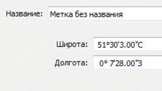
IP-the address - 32 -x bit number used to identify a computer on a network. It is customary to write the address in decimal values of each octet of this number, separating the received values with dots. For example, 192.168.101.36

IP addresses are unique, which means that each computer has its own combination of numbers, and there cannot be two computers on the network with the same addresses. IP-addresses are distributed centrally, ISPs make requests to national centers in accordance with their needs. The address ranges received by the providers are distributed further among the clients. Clients, in turn, can themselves act as a provider and distribute the received IP-addresses between subclients, etc. With this kind of distribution IP-addresses the computer system knows exactly the "location" of the computer, which has a unique IP-the address; - it is enough for it to send data to the "owner's" network, and the provider, in turn, will analyze the destination and, knowing who this part of the addresses is given to, will send information to the next owner of the subrange IP-addresses until the data reaches the destination computer.
For the construction of local networks, special address ranges are allocated. These are the addresses 10.x.x.x,192.168.x.x, 10.x.x.x, c 172.16.x.x on 172.31.x.x, 169.254.x.x, where under x- meaning any number that is from 0 before 254 . Packets transmitted from the specified addresses are not routed, in other words, they simply are not sent over the Internet, and therefore, computers in different local networks may have matching addresses from the specified ranges. That is, in the company OOO " Horns and hooves"and LLC" Vasya and company"there can be two computers with addresses 192.168.0.244 , but cannot, say, with addresses 85.144.213.122 received from the Internet provider, because no two are the same on the internet IP-addresses. To transfer information from such computers to the Internet and back, special programs and devices are used that replace local addresses with real ones when working with the Internet. In other words, data is sent to the Network from a real IP-addresses, not from local. This process happens invisibly to the user and is called address translation. I would also like to mention that within the same network, say, a company, LLC " Horns and hooves", there cannot be two computers with the same local IP address, i.e., in the above example, it meant that one computer with the address 192.168.0.244 in one company, the second with the same address - in another. In the same company, two computers with the address 192.168.0.244 simply won't get along.
You have probably heard terms such as external IP and internal IP, fixed (static IP) and variable (dynamic) IP. In a nutshell about them:
- external IP- it's just the same IP, which is given to you by the provider, i.e. Your unique Internet address, for example, - 85.144.24.122
- interior IP, is a local IP, i.e. Your IP in the local network, for example, - 192.168.1.3
- static IP- This IP, which does not change with each connection, i.e. secured to you firmly and forever
- dynamic IP, is floating IP-address that changes with each connection
Your type IP(static or dynamic) depends on the settings of the provider.
What is an address mask (subnet)
The concept of a subnet is introduced so that it is possible to distinguish a part IP-addresses of one organization, part of another, and so on. A subnet is a range of IP addresses that are considered to belong to the same local network. When working on a local network, information is sent directly to the recipient. If the data is destined for computers with an IP address that does not belong to the local network, then special rules are applied to them to calculate the route for forwarding from one network to another.

The mask is a parameter that tells the software how many computers are in a given group (subnet). The address mask has the same structure as the IP address itself: it is a set of four groups of numbers, each of which can be in the range from 0 to 255 . In this case, the smaller the mask value, the more computers are united in this subnet. For small company networks, the mask is usually 255.255.255.x(for example, 255.255.255.224). The netmask is assigned to the computer at the same time as the IP address. So, for example, the network 192.168.0.0 with a mask 255.255.255.0 may contain computers with addresses from 192.168.0.1 before 192.168.254 192.168.0.0 with a mask 255.255.255.128 allows addresses from 192.168.0.1 before 192.168.0.127 . I think the meaning is clear. As a rule, networks with a small possible number of computers are used by providers in order to save IP addresses. For example, a client may be assigned an address with a mask 255.255.255.252 . Such a subnet contains only two computers.
After the computer has obtained an IP address and knows the value of the subnet mask, the program can start working on this local subnet. However, in order to exchange information with other computers in the global network, you need to know the rules where to send information for the external network. For this, such a characteristic as the address of the gateway (Gateway) is used.
What is a Gateway
A gateway is a device (computer or router) that provides information forwarding between different IP subnets. If the program determines (by IP and mask) that the destination address is not part of the local subnet, then it sends this data to the device that acts as a gateway. The protocol settings indicate the IP address of such a device.
Do you want to know and be able to do more yourself?
We offer you training in the following areas: computers, programs, administration, servers, networks, site building, SEO and more. Find out the details now!
To work only in the local network, the gateway may not be specified.
For individual users connecting to the Internet, or for small businesses with a single connection channel, there should be only one gateway address in the system - this is the address of the device that has an Internet connection. If there are multiple routes, there will be multiple gateways. In this case, the routing table is used to determine the data transfer path.
What are routing tables
And so we slowly got to them. And so .. What kind of tables are these.

An organization or user can have several points of connection to the Internet (for example, backup channels in case something goes wrong with the first provider, but the Internet is still very necessary) or contain several IP-networks. In this case, in order for the system to know which way (through which gateway) to send this or that information, routing tables are used. The routing tables for each gateway indicate those Internet subnets for which information should be transmitted through them. At the same time, for several gateways, you can set the same ranges, but with different data transfer costs: for example, information will be sent over the channel that has the lowest cost, and if it fails for one reason or another, the next available most cheap connection.
What are network ports
When transferring data other than IP-addresses of the sender and recipient of the information packet contains port numbers. Example: 192.168.1.1: 80 , - in this case 80 is the port number. A port is a number that is used when receiving and transmitting data to identify the process (program) that must process the data. So if the packet is sent to 80 -th port, then this indicates that the information is intended for the server http.
Port numbers with 1 th to 1023 th are assigned to specific programs (the so-called well-known ports). Ports with numbers 1024 -65 535 can be used in programs of own development. In this case, possible conflicts should be resolved by the programs themselves by choosing a free port. In other words, the ports will be distributed dynamically: it is possible that at the next start the program will choose a different port value, unless, of course, you manually set the port through the settings.
What is a MAC address
The fact is that the packets forwarded on the network are addressed to computers not by their names and not to IP-the address. The packet is destined for a device with a specific address, which is called MAC-address.
MAC address- this is a unique address of a network device, which is embedded in it by the equipment manufacturer, i.e. this is a sort of stamped number of your network card. First half MAC-address is the identifier of the manufacturer, the second is the unique number of this device.
Usually MAC-address is sometimes required for identification, say, with a provider (if the provider uses a MAC address binding instead of a login-password) or when configuring a router.
Where to see all network settings
I almost forgot to say a few words about where you can look and change it all.
Let's assume that you have a poor command of network technologies, and do not even know the basics. But you were given a task: to quickly build an information network in a small enterprise. You have neither the time nor the inclination to study the thick Talmuds on network design, how to use network equipment, and delve into network security. And, most importantly, in the future you have no desire to become a professional in this field. Then this article is for you.
The second part of this article, which deals with the practical application of the basics outlined here:
The concept of the protocol stack
The task is to transfer information from point A to point B. It can be transmitted continuously. But the task becomes more complicated if it is necessary to transfer information between points A<-->B and A<-->C over the same physical channel. If information is transmitted continuously, then when C wants to transmit information to A, he will have to wait until B completes the transmission and releases the communication channel. Such a mechanism for transmitting information is very inconvenient and impractical. And to solve this problem, it was decided to divide the information into portions.At the recipient, these portions need to be compiled into a single whole, to receive the information that came out from the sender. But on recipient A, now we see portions of information from both B and C mixed up. This means that an identification number must be entered for each portion so that the recipient A can distinguish the pieces of information from B from the pieces of information from C and collect these portions into the original message. Obviously, the recipient must know where and in what form the sender attributed the identification data to the original piece of information. And for this they must develop certain rules for the formation and writing of identification information. Further, the word "rule" will be replaced by the word "protocol".
To meet the needs of modern consumers, it is necessary to specify several types of identification information at once. It also requires protection of transmitted portions of information both from random interference (during transmission over communication lines) and from deliberate sabotage (hacking). To do this, a portion of the transmitted information is supplemented by a significant amount of special, service information.
The Ethernet protocol contains the number of the sender's network adapter (MAC address), the number of the destination's network adapter, the type of data being transmitted, and the data being directly transmitted. A piece of information compiled in accordance with the Ethernet protocol is called a frame. It is believed that there are no network adapters with the same number. Network equipment extracts the transmitted data from the frame (hardware or software), and performs further processing.
As a rule, the retrieved data, in turn, is formed in accordance with the IP protocol and has a different kind of identification information - the recipient's ip address (a 4-byte number), the sender's ip address and data. As well as a lot of other necessary service information. Data generated in accordance with the IP protocol is called packets.
Next, the data is retrieved from the package. But this data, as a rule, is not yet the initially sent data. This piece of information is also compiled in accordance with a certain protocol. The most widely used protocol is TCP. It contains such identification information as the sender's port (a two-byte number) and the source's port, as well as data and service information. The extracted data from TCP is usually the data that the program running on computer B sent to the "receiver program" on computer A.
The nesting of protocols (in this case, TCP over IP over Ethernet) is called the protocol stack.
ARP: Address Resolution Protocol
There are class A, B, C, D and E networks. They differ in the number of computers and in the number of possible networks/subnets in them. For simplicity, and as the most common case, we will consider only a class C network whose ip address starts at 192.168. The next number will be the subnet number, followed by the network equipment number. For example, a computer with ip address 192.168.30.110 wants to send information to another computer with number 3, located in the same logical subnet. This means that the ip address of the recipient will be: 192.168.30.3It is important to understand that an information network node is a computer connected by one physical channel to switching equipment. Those. if we send data from the network adapter "to the wild", then they have one way - they will come out from the other end of the twisted pair. We can send absolutely any data formed according to any rule invented by us, without specifying either the ip address, or the mac address, or other attributes. And if that other end is connected to another computer, we can take them there and interpret them as we need. But if this other end is attached to the switch, then in this case the packet of information must be formed according to strictly defined rules, as if giving instructions to the switch what to do next with this packet. If the packet is formed correctly, then the switch will send it further, to another computer, as indicated in the packet. After that, the switch will delete this packet from its RAM. But if the package was not formed correctly, i.e. the instructions in it were incorrect, then the package will “die”, i.e. the switch will not send it anywhere, but will immediately delete it from its RAM.
To transfer information to another computer, three identification values \u200b\u200bmust be specified in the sent information packet - mac address, ip address and port. Relatively speaking, a port is a number that the operating system issues to each program that wants to send data to the network. The IP address of the recipient is entered by the user, or the program itself receives it, depending on the specifics of the program. The mac address remains unknown, i.e. the network adapter number of the recipient's computer. To obtain the necessary data, a "broadcast" request is sent, compiled according to the so-called "ARP address resolution protocol". Below is the structure of an ARP packet.

Now we do not need to know the values of all the fields in the above picture. Let's just focus on the main ones.
The fields contain the source ip address and destination ip address, as well as the source mac address.
The "Ethernet destination address" field is filled with units (ff:ff:ff:ff:ff:ff). Such an address is called a broadcast address, and such a frame is sent to all “interfaces on the cable”, i.e. all computers connected to the switch.
The switch, having received such a broadcast frame, sends it to all computers on the network, as if addressing everyone with the question: "if you are the owner of this ip address (destination ip address), please tell me your mac address." When another computer receives such an ARP request, it checks the destination ip address against its own. And if it matches, then the computer inserts its mac address in place of the units, swaps the ip and mac addresses of the source and destination, changes some service information and sends the packet back to the switch, which back to the original computer, the initiator of the ARP request.
This way your computer will know the mac address of the other computer you want to send data to. If there are several computers on the network at once responding to this ARP request, then we get an "ip address conflict". In this case, you need to change the ip address on the computers so that there are no identical ip addresses on the network.
Building networks
The task of building networks
In practice, as a rule, it is required to build networks, the number of computers in which will be at least one hundred. And besides the file-sharing features, our network must be secure and easy to manage. Thus, when building a network, three requirements can be distinguished:- Simplicity in management. If accountant Lida is transferred to another office, she will still need access to the computers of accountants Anna and Yulia. And if the information network is built incorrectly, the administrator may have difficulty in giving Lida access to the computers of other accountants in her new place.
- Security. To ensure the security of our network, access rights to information resources must be differentiated. The network must also be protected from disclosure, integrity, and denial of service threats. Read more in the book "Attack on the Internet" by Ilya Davidovich Medvedovsky, chapter "Basic concepts of computer security".
- Network speed. When building networks, there is a technical problem - the dependence of the transfer rate on the number of computers in the network. The more computers - the lower the speed. With a large number of computers, network performance can become so slow that it becomes unacceptable to the customer.
There are a large number of applications, software modules and services that, for their work, send broadcast messages to the network. Described in paragraph ARP: address determination protocol is only one of many loops that your computer sends to the network. For example, when you go to "Network Neighborhood" (Windows OS), your computer sends several more ALs with special information generated by the NetBios protocol to scan the network for computers that are in the same workgroup. After that, the OS draws the found computers in the "Network Neighborhood" window and you see them.
It is also worth noting that during the scanning process by one or another program, your computer sends not a single broadcast message, but several, for example, in order to establish virtual sessions with remote computers or for any other system needs caused by software problems. implementation of this application. Thus, each computer in the network is forced to send many different ALs to interact with other computers, thereby loading the communication channel with information that the end user does not need. As practice shows, in large networks, broadcast messages can make up a significant part of the traffic, thereby slowing down the network that is visible to the user.
Virtual LANs
To solve the first and third problems, as well as to help solve the second problem, the mechanism of partitioning the local network into smaller networks, like separate local networks (Virtual Local Area Network), is widely used. Roughly speaking, VLAN is a list of ports on the switch that belong to the same network. "One" in the sense that another VLAN will contain a list of ports belonging to another network.In fact, creating two VLANs on one switch is equivalent to buying two switches, i.e. creating two VLANs is like dividing one switch into two. Thus, a network of one hundred computers is divided into smaller networks, of 5-20 computers - as a rule, this number corresponds to the physical location of computers for the need for file sharing.
- When dividing the network into VLANs, ease of management is achieved. So, when the accountant Lida moves to another office, the administrator just needs to remove the port from one VLAN and add it to another. This is discussed in more detail in the VLANs, theory section.
- VLANs help solve one of the network security requirements, namely the demarcation of network resources. So, a student from one classroom will not be able to penetrate the computers of another classroom or the rector's computer, because. they are actually on different networks.
- Because our network is divided into VLANs, i.e. to small "like networks", the problem with broadcast messages disappears.
VLANs, theory
Perhaps the phrase “it is enough for the administrator to remove a port from one VLAN and add it to another” could be incomprehensible, so I will explain it in more detail. The port in this case is not a number issued by the OS to the application, as described in the Protocol Stack paragraph, but a socket (place) where you can attach (insert) an RJ-45 connector. Such a connector (i.e., a tip to a wire) is attached to both ends of an 8-wire wire, called a "twisted pair". The figure shows a 24-port Cisco Catalyst 2950C-24 switch:As mentioned in the ARP paragraph: address determination protocol, each computer is connected to the network by one physical channel. Those. 24 computers can be connected to a 24 port switch. The twisted pair cable physically permeates all the premises of the enterprise - all 24 wires from this switch are pulled to different rooms. Let, for example, 17 wires go and connect to 17 computers in the classroom, 4 wires go to the office of the special department and the remaining 3 wires go to the newly renovated, new accounting room. And the accountant Lida, for special merits, was transferred to this very office.
As mentioned above, VLANs can be represented as a list of ports belonging to the network. For example, there were three VLANs on our switch, i.e. three lists stored in the switch's flash memory. In one list the numbers 1, 2, 3 ... 17 were written, in another 18, 19, 20, 21 and in the third 22, 23 and 24. The lead computer was previously connected to the 20th port. And so she moved to another office. They dragged her old computer to a new office, or she sat down at a new computer - it doesn't matter. The main thing is that her computer was connected by a twisted pair cable, the other end of which is inserted into port 23 of our switch. And in order for her to continue sending files to her colleagues from her new location, the administrator must remove the number 20 from the second list and add the number 23. I note that one port can belong to only one VLAN, but we will break this rule at the end of this paragraph.
I also note that when changing the port membership in the VLAN, the administrator does not need to “poke” the wires in the switch. Moreover, he does not even have to get up from his seat. Because the administrator's computer is connected to the 22nd port, with which he can manage the switch remotely. Of course, thanks to special settings, which will be discussed later, only the administrator can manage the switch. For information on how to configure VLANs, see VLANs, practice [in the next article].
As you probably noticed, initially (in the Building Networks section) I said that there will be at least 100 computers in our network. But only 24 computers can be connected to the switch. Of course, there are switches with more ports. But there are still more computers in the corporate/enterprise network. And to connect an infinite number of computers to a network, switches are interconnected via the so-called trunk port (trunk). When configuring the switch, any of the 24 ports can be defined as a trunk port. And there can be any number of trunk ports on the switch (but it is reasonable to do no more than two). If one of the ports is defined as a trunk, then the switch forms all the information that has come to it into special packets, using the ISL or 802.1Q protocol, and sends these packets to the trunk port.
All incoming information - meaning, all the information that came to it from other ports. And the 802.1Q protocol is inserted into the protocol stack between Ethernet and the protocol by which the data was generated, which carries this frame.
In this example, as you probably noticed, the administrator is sitting in the same office with Lida, because the twisted time from ports 22, 23 and 24 leads to the same cabinet. Port 24 is configured as a trunk port. And the switchboard itself is located in the back room, next to the old accountants' office and the auditorium, which has 17 computers.
The twisted pair that goes from port 24 to the administrator's office connects to another switch, which in turn is connected to a router, which will be discussed in the following chapters. Other switches that connect other 75 computers and are located in other utility rooms of the enterprise - they all have, as a rule, one trunk port connected by twisted pair or fiber optics to the main switch, which is located in the office with the administrator.
It was said above that it is sometimes reasonable to make two trunk ports. The second trunk port in this case is used to analyze network traffic.
This is what large enterprise networks looked like back in the days of the Cisco Catalyst 1900 switch. You may have noticed two big disadvantages of such networks. First, using a trunk port causes some complexity and creates unnecessary work when configuring the equipment. And secondly, and most importantly, suppose that our "sort of networks" of accountants, economists and dispatchers want to have one database for three. They want the same accountant to be able to see the changes in the database that the economist or dispatcher made a couple of minutes ago. To do this, we need to make a server that will be available to all three networks.
As mentioned in the middle of this paragraph, a port can only be in one VLAN. And this is true, however, only for switches of the Cisco Catalyst 1900 and older series and for some younger models, such as the Cisco Catalyst 2950. For other switches, in particular the Cisco Catalyst 2900XL, this rule can be violated. When configuring ports in these switches, each port can have five modes of operation: Static Access, Multi-VLAN, Dynamic Access, ISL Trunk, and 802.1Q Trunk. The second mode of operation is exactly what we need for the above task - to give access to the server from three networks at once, i.e. make the server belong to three networks at the same time. This is also called VLAN traversal or tagging. In this case, the connection scheme may be as follows.
The TCP / IP protocol stack is the alpha and omega of the Internet, and you need to not only know, but also understand the model and how the stack works.
We figured out the classification, network standards and the OSI model. Now let's talk about the stack on the basis of which the worldwide system of unified computer networks Internet is built.
TCP/IP Model
Initially, this stack was created to connect large computers at universities over point-to-point telephone lines. But as new technologies emerged, broadcast (Ethernet) and satellite, it became necessary to adapt TCP/IP, which proved to be a difficult task. That is why, along with OSI, the TCP / IP model appeared.
Through the model, it is described how it is necessary to build networks based on various technologies so that the TCP / IP protocol stack works in them.

The table compares the OSI and TCP/IP models. The latter includes 4 levels:
- the lowest, network interface layer, provides interaction with network technologies (Ethernet, Wi-Fi, etc.). This is a combination of the functions of the data link and physical layers of OSI.
- Internet level stands higher, and in terms of tasks it has something in common with the network layer of the OSI model. It provides the search for the best route, including network troubleshooting. It is at this level that the router operates.
- Transport is responsible for communication between processes on different computers, as well as for the delivery of transmitted information without duplication, loss and errors, in the required sequence.
- Applied combines 3 layers of the OSI model: session, presentation and application. That is, it performs functions such as session support, protocol and information conversion, and user-network interaction.
Sometimes experts try to combine both models into something common. For example, below is a five-level representation of symbiosis from the authors of "Computer Networks" E. Tanenbaum and D. Weatherall:

The OSI model has good theoretical elaboration, but no protocols are used. With the TCP/IP model, things are different: the protocols are widely used, but the model is only suitable for describing networks based on TCP/IP.
Don't confuse them:
- TCP/IP is the protocol stack that is the backbone of the Internet.
- The OSI (Basic Reference Model for Open Systems Interconnection) model is suitable for describing a wide variety of networks.
TCP/IP protocol stack
Let's look at each level in more detail.

The lower level of network interfaces includes Ethernet, Wi-Fi and DSL (modem). These network technologies are not formally part of the stack, but are extremely important in the operation of the Internet as a whole.
The main network layer protocol is IP (Internet Protocol). It is a routed protocol, of which network addressing (IP address) is a part. Additional protocols such as ICMP, ARRP, and DHCP also work here. They make networks work.
At the transport level, TCP is located - a protocol that provides data transfer with a guarantee of delivery, and UDP - a protocol for fast data transfer, but without a guarantee.
The application layer is HTTP (for the web), SMTP (mail transfer), DNS (assigning friendly domain names to IP addresses), FTP (file transfer). There are more protocols at the application layer of the TCP / IP stack, but the ones given can be called the most significant to consider.
Keep in mind that the TCP/IP protocol stack defines the standards for communication between devices and contains internetworking and routing conventions.
When the article began to take shape, it was planned to fit into one, but by the end, the size of the article became unbearable, it was decided to divide the article into two: network theory and the operation of the network subsystem in Linux. Well, let's start with the theory...
TCP/IP protocol stack
Actually, what is a network? Network- these are more than 2 computers interconnected by some kind of wire communication channels, in a more complex example - by some kind of network equipment and exchanging information with each other according to certain rules. These rules are "dictated" the TCP/IP protocol stack.
Transmission Control Protocol/Internet Protocol (TCP/IP protocol stack)- in simple terms, this is a set of interacting protocols of different levels (it can be added that each level interacts with the neighboring one, that is, it docks, and therefore stack , IMHO, it's easier to understand), according to which data is exchanged on the network. Everyone protocol is a set of rules according to which data is exchanged. Total TCP/IP protocol stack- This set of rule sets A reasonable question may arise here: why have so many protocols? Is it really impossible to exchange everything using one protocol?
The thing is that each protocol describes strictly allotted him regulations. In addition, the protocols are separated by functionality levels, which allows the operation of network equipment and software to become much simpler, more transparent and perform "their" range of tasks.  To separate this set of protocols by levels, a OSI networking model(English) Open Systems Interconnection Basic Reference Model, 1978, it is also the basic reference model for the interaction of open systems). OSI model consists of seven different levels. The level is responsible for a separate section in the operation of communication systems, does not depend on adjacent levels - it only provides certain services. Each layer performs its task according to a set of rules called a protocol. The OSI model can be illustrated with the following figure: How is data transferred?
It can be seen from the figure that there is 7 levels of networking, which are divided into: application, view, session, transport, network, link, physical. Each layer contains its own set of protocols. The list of protocols by interaction levels is well presented on Wikipedia:
The TCP / IP protocol stack itself evolved in parallel with the adoption of the OSI model and did not "intersect" with it, resulting in a slight disagreement in the mismatch between the protocol stack and the layers of the OSI model. Usually, in TCP/IP stack upper 3 levels ( application, view and session) OSI models are combined into one - applied . Since such a stack does not provide a unified data transfer protocol, the functions for determining the type of data are transferred to the application. Simplified interpretation of the TCP/IP stack with respect to the OSI model can be represented like this:
This model of networking is also called DOD model(from bourgeois Department of Defense- US Department of Defense). So, we have considered the general idea of network interaction. For a deeper understanding of the essence of the issue, I can advise you to download and read the book ( Vito Amato "Fundamentals of Cisco T1 and T2 Networking"), below.
Addressing
In a network built on the TCP / IP protocol stack, each host (computer or device connected to the network) is assigned a 32-bit binary number. A convenient notation for an IP address (IPv4) is four decimal numbers (from 0 to 255) separated by dots, such as 192.168.0.1. In general, IP address divided into two parts: network (subnet) address and host address:
As can be seen from the illustration, there is such a thing as network and subnet. I think that from the meanings of the words it is clear that IP addresses are divided into networks, and networks, in turn, are divided into subnets using subnet masks(it would be more correct to say: host address can be subnetted). Initially, all IP addresses were divided into certain groups (classes of addresses/networks). And there was classful addressing, according to which networks were divided into strictly defined isolated networks:
It is easy to calculate that in total in the IP address space there are 128 networks with 16,777,216 Class A addresses, 16,384 networks with 65,536 Class B addresses, and 2,097,152 networks with 256 Class C addresses, as well as 268,435,456 multicast addresses and 134,317,728 reserved addresses. With the growth of the Internet, this system proved to be ineffective and was supplanted. CIDR(classless addressing), in which the number of addresses on the network is determined by the subnet mask.
There is also IP classification addresses as "private" and "public". The following address ranges are reserved for private (they are also local networks) networks:
- 10.0.0.0 - 10.255.255.255 (10.0.0.0/8 or 10/8),
- 172.16.0.0 - 172.31.255.255 (172.16.0.0/12 or 172.16/12),
- 192.168.0.0 - 192.168.255.255 (192.168.0.0/16 or 192.168/16).
- 127.0.0.0 - 127.255.255.255 reserved for loopback interfaces (not used for exchange between network nodes), so-called. localhost
In addition to the host address in a TCP / IP network, there is such a thing as a port. A port is a numerical characteristic of some system resource. A port is allocated to an application running on a network host to communicate with applications running on other network hosts (including other applications on the same host). From a programmatic point of view, a port is a memory area that is controlled by some service.
For each of the TCP and UDP protocols, the standard defines the possibility of simultaneously allocating up to 65536 unique ports on a host, identified by numbers from 0 to 65535. The correspondence between the port number and the service using this number can be found in the /etc/services file or on the website http:// www.iana.org/assignments/port-numbers. The entire range of ports is divided into 3 groups:
- 0 to 1023, called privileged or reserved (used for system and some popular programs)
- 1024 - 49151 are called registered ports.
- 49151 - 65535 are called dynamic ports.
IP protocol, as can be seen from the illustrations is below TCP and UDP in the protocol hierarchy and is responsible for the transmission and routing of information on the network. To do this, the IP protocol wraps each piece of information (TCP or UDP packet) into another packet - an IP packet or an IP datagram - that stores a header about the source, destination, and route.
In a real-world analogy, a TCP/IP network is a city. Street and alley names are networks and subnets. Building numbers are host addresses. In buildings, office/apartment numbers are ports. More precisely, ports are mailboxes where recipients (services) are waiting for mail to arrive. Accordingly, the port numbers of the cabinets are 1,2, etc. are usually given to directors and managers as privileged, and ordinary employees get office numbers with large numbers. When sending and delivering correspondence, information is packed into envelopes (ip-packets), which indicate the sender's address (ip and port) and the recipient's address (ip and port). In simple terms, something like this...
It should be noted that the IP protocol has no idea about ports, TCP and UDP are responsible for interpreting ports, by analogy, TCP and UDP do not process IP addresses.
In order not to remember unreadable sets of numbers in the form of IP addresses, but to indicate the machine name in the form of a human-readable name, such a service was "invented" as DNS (Domain Name Service), which takes care of resolving hostnames to IP addresses and is a huge distributed database. I will definitely write about this service in future posts, but for now it is enough for us to know that for the correct translation of names into addresses, a daemon must be running on the machine named or the system must be configured to use the ISP's DNS service.
Routing
Let's take a look at (in the illustration) an example of an infrastructure with multiple subnets. The question may arise, but how can one computer connect to another? How does he know where to send packets?
To resolve this issue, the networks are interconnected gateways (routers). Gateway- this is the same host, but connected to two or more networks, which can transfer information between networks and forward packets to another network. In the figure, the role of the gateway is played by pineapple and papaya having 2 interfaces connected to different networks.
To determine packet path, IP uses the network part of the address ( subnet mask). To determine the route, each machine on the network has routing table(routing table), which stores a list of networks and gateways for these networks. IP "looks" the network part of the destination address in a passing packet and if there is an entry in the routing table for that network, then the packet is sent to the appropriate gateway.
On Linux, the operating system kernel keeps the routing table in a file /proc/net/route. You can view the current routing table with the command netstat -rn(r - routing table, n - don't resolve IPs to names) or route . First column command output netstat -rn (Destination- destination) contains addresses of networks (hosts) destination. In this case, when specifying a network, the address usually ends with a zero. Second column (Gateway)- the gateway address for the host/network specified in the first column. Third column (Genmask)- subnet mask for which this route works. Flags column gives information about the destination address (U - the route is up (Up), N - the route for the network (network), H - the route for the host, etc.). MSS column shows the number of bytes that can be sent at a time, Window- the number of frames that can be sent before receiving confirmation, irtt- route usage statistics, face- specifies the network interface used for the route (eth0, eth1, etc.)
As you can see in the example below, the first entry (line) is for the network 128.17.75, all packets for this network will be sent to the gateway 128.17.75.20, which is the IP address of the host itself. The second entry is default route, which applies to all packets sent on networks not listed in this routing table. Here the route is through the papaya host (IP 128.17.75.98), which can be considered a door to the outside world. This route must be written on all machines on the 128.17.75 network that must have access to other networks. The third entry was made for loopback interface. This address is used if the machine needs to connect to itself using the TCP/IP protocol. The last entry in the routing table is for IP 128.17.75.20 and is routed to the lo interface, so when a machine connects to itself at 128.17.75.20, all packets will be sent to interface 127.0.0.1.
If the host egg plant wishes to send a packet to the host zucchini, (accordingly, the packet will contain the sender - 128.17.75.20 and the recipient - 128.17.75.37), the IP protocol will determine based on the routing table that both hosts belong to the same network and will send the packet directly to the network, where zucchini will receive it. In more detail.. the network card is broadcasting an ARP request "Who is IP 128.17.75.37, is it shouting 128.17.75.20?" all machines that received this message ignore it, and the host with the address 128.17.75.37 replies "It's me and my MAC address is such and such..." arp tables, in which the correspondence of IP-MAC addresses is entered. "Screams", that is, this packet is sent to all hosts, this is because the destination MAC address is the broadcast address (FF:FF:FF:FF:FF:FF). Such packets are received by all hosts on the network.
Host Routing Table Example egg plant:
# netstat -rn Kernel IP routing table Destination Gateway Genmask Flags MSS Window irtt Iface 128.17.75.0 128.17.75.20 255.255.255.0 UN 1500 0 0 eth0 default 128.17.75.98 0.0.0.0 UGN 1500 0 0 eth0 125.0.21 0.0 UH 3584 0 0 lo 128.17.75.20 127.0.0.1 255.255.255.0 UH 3584 0 0 lo
Let's consider the situation where the host egg plant wants to send a packet to the host, for example, pear or even further? .. In this case, the recipient of the packet will be - 128.17.112.21, IP protocol will try to find a route for the network 128.17.112 in the routing table, but this route is not in the table, so it will be selected default route, whose gateway is papaya(128.17.75.98). After receiving the package papaya look up the destination address in its routing table:
# netstat -rn Kernel IP routing table Destination Gateway Genmask Flags MSS Window irtt Iface 128.17.75.0 128.17.75.98 255.255.255.0 UN 1500 0 0 eth0 128.17.112.0 128.17.112.3 255.255.255.0 UN 1500 0 0 eth1 default 128.17.112.40 0.0. 0.0 UGN 1500 0 ETH1 127.0.0.1 127.0.1 255.0.0 UH 3584 0 0 LO 128.17.75.98 127.0.1 255.255.255.2 UH 3584 0 LO 128.17.112.3 127.0.1 255.255.0 UH 3584 0 LO 0 LO 0 LO 0 LO 0 LO 0 LO 0 LO 0 LO
From the example it can be seen that papaya connected to two networks 128.17.75, through the device eth0 and 128.17.112 through the device eth1. Default route, via host pineapple, which in turn is a gateway to the external network.
Accordingly, having received a package for pear, router papaya will see that the destination address belongs to the network 128.17.112 and will route the packet according to the second entry in the routing table.
Thus, packets are passed from router to router until they reach the destination address.
It should be noted that in these examples the routes
128.17.75.98 127.0.0.1 255.255.255.0 UH 3584 0 0 lo 128.17.112.3 127.0.0.1 255.255.255.0 UH 3584 0 0 lo
Not standard. And in modern linux you will not see this.
Summary
In this article, I tried to briefly and clearly describe the basic concepts of network infrastructure interaction using the example of several interconnected networks, in the next part I will describe the operation of the network in the Linux operating system. I will be glad to your comments and additions.