Antenna is a radio engineering device designed to receive and emit electromagnetic waves through the air.
To watch TV in high quality, it is best to connect the TV to cable network. In conditions of a great distance from the city, an alternative is an antenna (dish) of satellite television. But there are situations when these options cannot be used. In this case, you can make a simple television antenna from improvised material with your own hands.
If you live at a distance of line of sight from a television tower, then the simplest indoor television antenna, the design of which is presented in this article, is quite suitable for receiving an analog and digital television signal. This television indoor antenna is designed to receive TV programs in the UHF range (470-790 MHz), but with enough strong signal satisfactorily receives the signal of the meter range (48.5-100 MHz, 174-230 MHz).
The design of a television antenna is simple and does not require special knowledge to repeat. For its manufacture, you will need 70 cm of copper wire with a diameter of 2-3 mm, a piece of a sheet of double-sided fiberglass, 1.5 m of a coaxial television cable with a characteristic impedance of 75 ohms and an F-plug.
Instructions for the manufacture of a television UHF antenna
The first thing you need is to pick up a piece of copper wire with a diameter of 2-3 mm and a length of 70 cm. For these purposes, a single-core copper wire is well suited for laying electrical wiring. If there are several conductors in the cable, then one conductor must be carefully cut along the groove, being careful not to damage the insulation. It is not needed for the antenna to work, the insulation is left only for an aesthetic appearance. An aluminum wire is also suitable, but then it will have to be connected to the contacts of the matching transformer board using a threaded connection. Please note that the nut should not touch the shielding foil of the transformer, if it does, then you need to lay an insulating washer or cut the foil.

If a wire without insulation is used, then for beauty you can put a vinyl chloride tube on it.

Next, the wire must be bent into a ring with a diameter of approximately 220 mm. Here high accuracy need not. For this, a mandrel in the form of a bucket of paint or any other round container of a suitable size is well suited.
When the ring for the antenna is ready, you can begin to manufacture the printed circuit board of the matching transformer.

The printed circuit board is made of fiberglass or foil-coated getinax on both sides, 1.5 mm thick, 25 × 30 mm in size. The photo shows appearance transformer printed circuit board on both sides.

In this photo, the negative of the antenna circuit board. The width of the current-carrying tracks is 1 mm, the distance between the tracks is 1.5 mm. The size of the antenna board is 25×30 mm.
If it is not possible to make a printed circuit board for the manufacture of the antenna by a chemical method, then it can be made mechanically. To do this, remove unnecessary sections of the foil, leaving only pads, and lay out the current-carrying tracks from a copper wire with a diameter of 0.3-0.5 mm, gluing it to the board, for example, with Moment glue.
To give an aesthetic appearance and increase the mechanical strength of the antenna, the transformer is placed in a plastic or metal box, in which holes for the ring and antenna cable are pre-drilled.

When all the details are prepared, you can start assembling the antenna. The ends of the ring, pre-tinned with solder, are wound into a box and bent at a right angle at a distance of 3 mm. Next, the ends are inserted into the printed circuit board of the antenna transformer and soldered with a soldering iron.

The antenna board is rotated to the bottom of the box and secured with an M3 screw and nut.
A television cable with a wave impedance of 75 ohms, 1.5-1.8 m long, is threaded into the hole in the box. You can learn about choosing the type of cable and cutting it, installing the F-connector from the article “Connecting a TV to an antenna cable”. At one end, you first need to install a television F-connector, and cut the other end and solder its ends to a printed circuit board. The center core of the cable is soldered directly to the right end of the ring, and the braided shield is soldered directly to the antenna board foil.
For reliable operation of the antenna, solder or fasten the cable in the following order. First, the shielding braid is soldered, then the cable must be pulled well to take up the slack, and only after that the central core must be soldered. In this case, when moving the antenna in order to find a place in the room with the maximum signal level and pulling the cable, the central core will not break.

If the cable screen is made of aluminum foil, then it can be pressed against the board foil using a metal clamp, put on a screw and secured with a nut. The technology for attaching the screen with a clamp is discussed in the article "How to make a TV crab with your own hands".
It remains to close the box with a lid, insert the connector into the TV and set the channels to desired programs. In order for the image quality to be with minimal noise, you need to move the antenna around the room in order to find a place with the maximum television signal.
How to replace the matching PCB
cable loop
The use of a printed circuit board to match the antenna with a coaxial cable allows you to make the antenna more compact.

If there is no desire or opportunity to make a printed circuit board, then without losing the quality of the antenna, it can be replaced with a loop, which I also call a U-elbow, which is a segment of a television cable bent in half connected to the antenna according to the scheme, as in the photo below.

To make a matching loop, you need to take a piece of television cable 162 mm long, with which the antenna will be connected to the TV. Cut its ends and solder the central wires to the ends of the ring, the distance between which should be 60 mm. Next, the end of the cable going to the TV is cut and its central core is soldered to either end of the antenna ring, and the shield wire is connected to the shield wires of the loop, as shown in the photograph.
When soldering the shielding braid, care must be taken not to melt the insulation of the central core, and the braid does not come into contact with it.
The photo shows the soldering of the cable to the antenna ring, made of aluminum wire with a diameter of 3mm. Since it is difficult to solder wires to aluminum with soft solder, the ends of the ring were slightly flattened, holes were drilled in them and brass petals were fixed with rivets. The central conductors of the cable to the petals were soldered securely.
In summer cottages, a television signal can rarely be received without amplification: it is too far from the repeater, the terrain is usually uneven, and trees interfere. For the normal quality of the “picture”, antennas are needed. Anyone who knows how to handle a soldering iron at least a little can make an antenna for giving with his own hands. Aesthetics outside the city is not given so much importance, the main thing is the quality of reception, simple design, low cost and reliability. You can experiment and do it yourself.
A simple TV antenna
If the repeater is located within 30 km from your dacha, you can make the simplest receiving part in design. These are two identical tubes connected by a cable. The output of the cable is fed to the corresponding input of the TV.
The design of the antenna for the TV in the country: it is very easy to do it yourself (to increase the size of the picture, click on it with the left mouse button)
What you need to make this TV antenna
First of all, you need to find out what frequency the nearest TV tower is broadcasting on. The length of the "whiskers" depends on the frequency. The broadcast band is in the range of 50-230 MHz. It is divided into 12 channels. Each needs its own length of tubes. Channel List on-air television, their frequencies and parameters of a television antenna for self-production will be given in the table.
| Channel number | Channel frequency | Vibrator length - from one to the other end of the tubes, cm | Length of cables for matching device, L1/L2 cm |
|---|---|---|---|
| 1 | 50 MHz | 271-276 cm | 286 cm / 95 cm |
| 2 | 59.25 MHz | 229-234 cm | 242 cm / 80 cm |
| 3 | 77.25 MHz | 177-179 cm | 187 cm / 62 cm |
| 4 | 85.25 MHz | 162-163 cm | 170 cm / 57 cm |
| 5 | 93.25 MHz | 147-150 cm | 166 cm / 52 cm |
| 6 | 175.25 MHz | 85 cm | 84 cm / 28 cm |
| 7 | 183.25 MHz | 80 cm | 80 cm / 27 cm |
| 8 | 191.25 MHz | 77 cm | 77 cm / 26 cm |
| 9 | 199.25 MHz | 75 cm | 74 cm / 25 cm |
| 10 | 207.25 MHz | 71 cm | 71 cm / 24 cm |
| 11 | 215.25 MHz | 69 cm | 68 cm / 23 cm |
| 12 | 223.25 MHz | 66 cm | 66 cm / 22 cm |
So, in order to make a TV antenna with your own hands, you need the following materials:

It would be nice to have a soldering iron, flux for soldering copper and solder on hand: it is advisable to solder all the connections of the central conductors: the image quality will be better and the antenna will last longer. The places of soldering then need to be protected from oxidation: it is best to fill it with a layer of silicone, you can use epoxy, etc. As a last resort, seal it with electrical tape, but this is very unreliable.
This homemade TV antenna, even at home, will be made by a child. You need to cut the tube of the length that matches the broadcast frequency of the nearby repeater, then cut it exactly in half.
Assembly order
The resulting tubes are flattened on one side. With these ends they are attached to the holder - a piece of getinax or textolite 4-6 mm thick (see figure). The tubes are placed at a distance of 6-7 cm from each other, their far ends should be at the distance indicated in the table. They are fixed to the holder with clamps, they must hold firmly.
The installed vibrator is fixed on the mast. Now you need to connect two "whiskers" through a matching device. This is a cable loop with a resistance of 75 ohms (type RK-1, 3, 4). Its parameters are indicated in the rightmost column of the table, and how it is done is on the right side of the photo.
The middle cores of the cable are screwed (soldered) to the flattened ends of the tubes, their braid is connected with a piece of the same conductor. It is easy to get the wire: cut off a piece from the cable a little more than the required size and free it from all shells. Strip the ends and screw to the cable conductors (it is better to solder).
Then the central conductors from two pieces of the matching loop and the cable that goes to the TV are connected. Their braid is also connected copper wire.
The last action: the loop in the middle is attached to the bar, and the cable going down is screwed to it. The bar is raised to the required height and “tuned” there. Two people are needed to set up: one turns the antenna, the second watches TV and evaluates the picture quality. Having determined where the signal is best received from, the do-it-yourself antenna is fixed in this position. In order not to suffer for a long time with the "tuning", look where the neighbors' receivers (terrestrial antennas) are directed. The simplest antenna for giving with your own hands is made. Set and "catch" the direction by turning it along its axis.
Watch the video on how to cut a coaxial cable.
;
Loop from a pipe
This do-it-yourself antenna is a little more difficult to manufacture: you need a pipe bender, but the reception radius is larger - up to 40 km. The starting materials are almost the same: a metal tube, a cable and a rod.
The bend radius of the pipe is not important. It is necessary that the pipe has the required length, and the distance between the ends is 65-70 mm. Both "wings" should be the same length, and the ends should be symmetrical about the center.

Homemade antenna for a TV: a TV signal receiver with a reception radius of up to 40 km is made from a piece of pipe and cable (to enlarge the picture, click on it with the left mouse button)
The length of the pipe and cable is shown in the table. Find out at what frequency the repeater closest to you is broadcasting, select the appropriate line. Saw off the pipe of the required size (diameter is preferably 12-18 mm, for them the parameters of the matching loop are given).
| Channel number | Channel frequency | Vibrator length - from one end to the other, cm | Cable length for matching device, cm |
|---|---|---|---|
| 1 | 50 MHz | 276 cm | 190 cm |
| 2 | 59.25 MHz | 234 cm | 160 cm |
| 3 | 77.25 MHz | 178 cm | 125 cm |
| 4 | 85.25 MHz | 163 cm | 113 cm |
| 5 | 93.25 MHz | 151 cm | 104 cm |
| 6 | 175.25 MHz | 81 cm | 56 cm |
| 7 | 183.25 MHz | 77 cm | 53 cm |
| 8 | 191.25 MHz | 74 cm | 51 cm |
| 9 | 199.25 MHz | 71 cm | 49 cm |
| 10 | 207.25 MHz | 69 cm | 47 cm |
| 11 | 215.25 MHz | 66 cm | 45 cm |
| 12 | 223.25 MHz | 66 cm | 44 cm |
Assembly
The tube of the required length is bent, making it absolutely symmetrical about the center. One edge is flattened and brewed / sealed. Fill with sand, and close up the second side. If there is no welding, you can plug the ends, just put the plugs on good glue or silicone.
The resulting vibrator is fixed on the mast (rod). They are screwed to the ends of the pipe, and then the central conductors of the matching loop and the cable that goes to the TV are soldered. The next step- connect the cable braid with a piece of copper wire without insulation. The assembly is completed - you can proceed to the "configuration".
beer can antenna
Despite the fact that she looks frivolous, the image becomes much better. Checked multiple times. Try it!
Beer can outdoor antenna

We collect like this:
- We drill a hole in the bottom of the jar strictly in the center (5-6 mm in diameter).
- Through this hole we stretch the cable, we bring it out through the hole in the cover.
- We fix this jar on the left on the holder so that the cable is directed to the middle.
- We take out the cable from the can by about 5-6 cm, remove the insulation by about 3 cm, disassemble the braid.
- We cut the braid, its length should be about 1.5 cm.
- We distribute it over the surface of the can and solder it.
- The central conductor sticking out by 3 cm must be soldered to the bottom of the second can.
- The distance between the two banks must be made as small as possible, and fixed in some way. One option is sticky tape or duct tape.
- That's it, the homemade UHF antenna is ready.
End the other end of the cable with a suitable plug, plug it into the TV socket you need. By the way, this construction can be used to receive digital television. If your TV supports this signal format (DVB T2) or there is a special set-top box for an old TV, you can catch a signal from the nearest repeater. You just need to find out where it is and direct your own television antenna made from tin cans there.

Simple homemade antennas can be made from cans (from beer or drinks). Despite the frivolity of the "components", it works very well, and is made very simply.
The same design can be adapted to receive VHF channels. Instead of 0.5 liter jars, put on 1 liter. Will receive MW band.
Another option: if you don’t have a soldering iron, or you don’t know how to solder, you can make it easier. Tie two cans at a distance of a few centimeters to the holder. Strip the end of the cable by 4-5 centimeters (carefully remove the insulation). Separate the braid, twist it into a bundle, make a ring out of it, into which you insert a self-tapping screw. From the central conductor, make a second ring and thread the second self-tapping screw through it. Now, at the bottom of one can, you clean (with sandpaper) a speck to which you screw the screws.
Actually for better contact soldering is needed: it is better to tin and solder the braid ring, as well as the place of contact with the metal of the can. But even on self-tapping screws it turns out well, however, the contact is periodically oxidized and needs to be cleaned. As it “snows” you will know why ...
Do-it-yourself digital TV antenna
Antenna design - frame. For this version of the receiver, you will need a crosspiece made of wooden boards and a television cable. You will also need electrical tape, a few nails. All.
We have already said that to receive a digital signal, only a decimeter terrestrial antenna and the corresponding decoder. It can be built into TVs (new generation) or made as a separate device. If the TV has a signal reception function in the DVB T2 code, connect the antenna output directly to the TV. If your TV does not have a decoder, you will need to purchase digital set-top box and connect the output from the antenna to it, and connect it to the telly.
How to determine the channel and calculate the perimeter of the frames
In Russia, a program has been adopted, according to which towers are constantly being built. By the end of 2015, the entire area should be covered by repeaters. On the official website http://xn--p1aadc.xn--p1ai/when/ find the closest tower to you. It shows the broadcast frequency and channel number. The perimeter of the antenna frame depends on the channel number.

For example, channel 37 broadcasts at a frequency of 602 MHz. The wavelength is considered as follows: 300 / 602 \u003d 50 cm. This will be the perimeter of the frame. Let's calculate the other channel in the same way. Let it be channel 22. Frequency 482 MHz, wavelength 300/482 = 62 cm.
Since this antenna consists of two frames, the length of the conductor must be equal to twice the wavelength, plus 5 cm per connection:
- for channel 37 we take 105 cm of copper wire (50 cm * 2 + 5 cm = 105 cm);
- for 22 channels you need 129 cm (62 cm * 2 + 5 cm = 129 cm).
Assembly
Copper wire is best used from the cable that will go further to the receiver. That is, take the cable and remove the sheath and braid from it, freeing the central conductor of the desired length. Be careful not to damage it.
- for channel 37: 50 cm / 4 = 12.5 cm;
- for 22 channels: 62 cm / 4 = 15.5 cm.
The distance from one nail to another must correspond to these parameters. Laying copper wire start on the right, from the middle, moving down and further along all points. Only in the place where the frames come close to one another, do not short the conductors. They should be at some distance (2-4 cm).

When the entire perimeter is laid, the braid from a cable a few centimeters long is twisted into a bundle and soldered (wound if it is not possible to solder) to the opposite edge of the frame. Next, the cable is laid as shown in the figure, winding it with electrical tape (more often, but the laying route cannot be changed). Then the cable goes to the decoder (separate or built-in). All the antenna for giving with your own hands for receiving digital television is ready.
How to make an antenna for digital television with your own hands - another design - is shown in the video.
1. Do-it-yourself UHF television antenna
1.
Ring-coaxial cable PK75 530mm long.
2.
Loop-coaxial cable PK75 175mm long.
3.
To the antenna.
Assembly:
To assemble this antenna, you do not even have to run around the shops.
For this you need to take antenna cable PK75 530mm long (for the ring) and 175mm. (for loop).
Connect as shown in the figure.
Fasten to a sheet of plywood (plexiglass) using wire ties.
Direct to telecentre.
Here's to you UHF antenna, which will work no worse than the purchased one.
2. Do-it-yourself television antenna DMV "Narodnaya"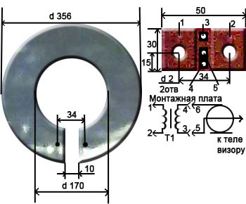
The antenna is an aluminum disk with an outer diameter of 356mm and an inner diameter of 170mm. and 1mm thick., in which a 10mm wide cut was made.
A printed circuit board made of fiberglass 1 mm thick is installed in place of the cut. This board has two holes for fixing with M3 screws.
The terminals of the matching transformer T1 are soldered to the printed circuit board attached to the antenna.
For a transformer, it is best to use a ring core with an outer diameter of 6 ... 10 mm., Internal - 3 ... 7 mm. and 2…3 mm thick.
The transformer windings are superimposed with a single-layer insulated wire with a diameter of 0.2 ... 0.25 mm. and have the same number of turns, from 2 to 3 turns. The length of the turns of the turns is 20mm.
In the presence of such a transformer, reception is possible in the meter and decimeter range at a distance of 25 ... 30 km. At a distance of up to 50 km. the antenna works satisfactorily only on UHF channels.
Without a transformer, the reliable reception distance is halved.
However, there is a circuit that allows you to get similar results without a transformer, for this you need to assemble the following circuit: 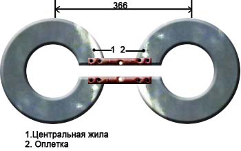
3. Do-it-yourself television log-periodic antenna (UHF).


BUT. Mast
AT. Metal plate (dimensions 87x30x5)
FROM. metal tubes d 16…19mm
D. textolite plate (dimensions 87x30x5)
E. braid
F. coaxial cable
G. central vein
7,6,5,4,3,2,1. vibrators
Assembly
1. Take two metal tubes 450mm long and 16…19mm in diameter.
2. Make two plates with dimensions 87x30x5mm. (one of metal, the other of textolite), drill holes in them, as shown in the figures.
3. Fix the tubes in the plates (to the metal for soldering, and to the textolite with screws screwed from the ends of the plate with a diameter of 2.5 mm.
4. In metal tubes, along their length, at the distances indicated in the figure, drill holes with a diameter of 3.3 mm. and cut the M4 thread.
5. Screw into the holes 14 directors made of a bar with a diameter of 5 mm. At one end of each bar, cut an M4 thread, 10mm long.
The lengths of the directors, taking into account the part of the length of the threaded end, according to the number of the vibrator (see Fig.), are given in the table:
No. of vibrator…..length in mm…..number of pieces
1…………………………..107………………..2
2…………………………..129………………..2
3…………………………..155………………..2
4…………………………..186………………..2
5…………………………..225………………..2
6…………………………..272………………..2
7…………………………..330………………..2
6. Pass the coaxial cable in one of the tubes and unsolder it according to the figure. Paint the solder ends with paint.
7. Attach the antenna to the mast.
Antenna from user Evgen:
1. Take two EMPTY jars - for channels from 21 to 41 it is better than 0.5 l, for 42 - 69 - 0.33 l.
2. Fix them with any convenient way(duct tape, adhesive tape, rope, glue, etc.) on a solid piece of dielectric (rail, stick, piece of plywood - it is better to paint or varnish the tree, textolite, getinax, etc.) at a distance of 10 - 15 mm from each other friend.
3. We make holes of 2.5 - 4 mm along the edges of each jar (which screws-washers-gadgets are found) and with the help of these we attach the central core of the cable to one jar, and the braid to the other. You can attach any balancing device, but you can do without it.
The receiving distance depends on the installation location of this design (outside is better) and the power of the transmitter.
Holes are on those edges where the jars are closer to each other. And it’s more convenient to first fix the cable (and the balancing device - if you’re too lazy), and then the jars to the supporting structure.
Once a good television antenna was in short supply, purchased quality and durability, to put it mildly, did not differ. Making an antenna for a “box” or “coffin” (an old tube TV) with your own hands was considered an indicator of skill. Interest in homemade antennas does not fade away even today. There is nothing strange here: TV reception conditions have changed dramatically, and manufacturers, believing that there is nothing essentially new in the theory of antennas and there will not be, most often adapt electronics to well-known designs, without thinking about the fact that The main thing for any antenna is its interaction with the signal on the air.
What has changed on the air?
Firstly, almost the entire volume of TV broadcasting is currently carried out in the UHF band. First of all, for economic reasons, it greatly simplifies and reduces the cost of the antenna-feeder economy of transmitting stations, and, more importantly, the need for its regular maintenance by highly qualified specialists engaged in hard, harmful and dangerous work.
Second - TV transmitters now cover almost all more or less populated places with their signal, and a developed communication network ensures the delivery of programs to the most remote corners. There, broadcasting in the habitable zone is provided by low-power, unattended transmitters.
Third, the conditions for the propagation of radio waves in cities have changed. On the UHF, industrial interference leaks weakly, but reinforced concrete high-rise buildings for them are good mirrors, repeatedly reflecting the signal until it is completely attenuated in the zone of seemingly confident reception.
Fourth - There are a lot of TV programs on the air now, dozens and hundreds. How diverse and meaningful this set is is another question, but it is now meaningless to count on receiving 1-2-3 channels.
Finally, development of digital broadcasting. The DVB T2 signal is something special. Where it still exceeds the noise even a little, by 1.5-2 dB, the reception is excellent, as if nothing had happened. And a little further or to the side - no, as cut off. The "digit" is almost insensitive to interference, but if there is a mismatch with the cable or phase distortions anywhere in the path, from the camera to the tuner, the picture can crumble into squares even with a strong clean signal.
Antenna Requirements
In accordance with the new reception conditions, the basic requirements for TV antennas have also changed:
- Its parameters such as directivity coefficient (DAC) and protective action coefficient (CPA) do not have a decisive value now: modern ether is very dirty, and along the tiny side lobe of the directivity pattern (DN), at least some kind of interference, yes it will crawl through, and it is necessary to deal with it by means of electronics.
- Instead, the intrinsic gain of the antenna (KU) is of particular importance. An antenna that “catches” the air well, and does not look at it through a small hole, will provide a power reserve for the received signal, allowing the electronics to clear it of noise and interference.
- A modern television antenna, with rare exceptions, must be a band antenna, i.e. its electrical parameters should be kept in a natural way, at the level of theory, and not squeezed into acceptable limits by engineering tricks.
- The TV antenna must be coordinated in the cable over its entire operating frequency range without additional devices matching and balancing (USS).
- The frequency response of the antenna (AFC) should be as smooth as possible. Sharp surges and dips are inevitably accompanied by phase distortions.
The last 3 points are due to admission requirements digital signals. Customized, i.e. operating theoretically at the same frequency, antennas can be "stretched" in frequency, for example. antennas of the "wave channel" type on the UHF with an acceptable signal-to-noise ratio capture channels 21-40. But their coordination with the feeder requires the use of OSS, which either strongly absorb the signal (ferrite), or spoil the phase response at the edges of the range (tuned). And such an antenna, which works perfectly on an “analog”, will receive a “digit” badly.
In this regard, from all the great antenna variety, this article will consider TV antennas available for self-manufacturing, of the following types:
- Frequency independent (all-wave)- does not differ in high parameters, but is very simple and cheap, it can be done in just an hour. Outside the city, where the air is cleaner, it will be able to receive a digital or a fairly powerful analogue not a short distance from the television center.
- Range log-periodic. Figuratively speaking, it can be likened to a fishing trawl, which sorts prey when it is caught. It is also quite simple, perfectly consistent with the feeder in its entire range, absolutely does not change the parameters in it. The technical parameters are average, therefore it is more suitable for giving, and in the city as a room.
- Several modifications zigzag antenna , or Z-antennas. In the MV range, this is a very solid design that requires considerable skill and time. But on the UHF, due to the principle of geometric similarity (see below), it is so simplified and shrinks that it can be used as a highly efficient indoor antenna under almost any reception conditions.
Note: The Z-antenna, to use the previous analogy, is a frequent nonsense, raking up everything that is in the water. As the air became littered, it fell out of use, but with the development of digital TV, it again found itself on a horse - in its entire range it is just as perfectly coordinated and keeps the parameters as a “speech therapist”.
Precise matching and balancing of almost all the antennas described below is achieved by laying the cable through the so-called. point of zero potential. She is presented with special requirements, which will be discussed in more detail below.
About vibrator antennas
Up to several tens of digital channels can be transmitted in the frequency band of one analog channel. And, as already mentioned, the figure works with an insignificant signal-to-noise ratio. Therefore, in places very remote from the television center, where the signal of one or two channels barely finishes, for receiving digital TV, the good old wave channel (AVK, wave channel antenna), from the class of vibrator antennas, can also be used, so at the end we will devote a few lines and to her.
About satellite reception
There is no point in making a satellite dish yourself. You still need to buy a head and a tuner, and behind the external simplicity of the mirror lies a parabolic surface of oblique incidence, which not everyone can perform with the required accuracy. industrial enterprise. The only thing that homemade people can do is set up a satellite dish, about that.
About antenna parameters
The exact determination of the antenna parameters mentioned above requires knowledge of higher mathematics and electrodynamics, but it is necessary to understand their meaning when starting to manufacture an antenna. Therefore, we give a somewhat rough, but still clarifying definition (see the figure on the right):

- KU - the ratio of the signal power received by the antenna to the main (main) lobe of its DN, to its same power, received in the same place and at the same frequency, omnidirectional, with a circular, DN, antenna.
- KND is the ratio of the solid angle of the entire sphere to the solid angle of the opening of the main lobe of the RP, assuming that its cross section is a circle. If the main lobe has different sizes in different planes, you need to compare the area of \u200b\u200bthe sphere and the cross-sectional area of \u200b\u200bit by its main lobe.
- CPD is the ratio of the signal power received to the main lobe to the sum of the interference powers at the same frequency received by all side (back and side) lobes.
Notes:
- If the antenna is a band antenna, the powers are considered at the frequency of the useful signal.
- Since there are no completely omnidirectional antennas, a half-wave linear dipole oriented in the direction of the electric field vector (along its polarization) is taken as such. Its KU is considered equal to 1. TV programs are transmitted with horizontal polarization.
It should be remembered that KU and KND are not necessarily interconnected. There are antennas (for example, "spy" - a single-wire traveling wave antenna, ABC) with high directivity, but unity or less gain. Such look into the distance as if through a diopter sight. On the other hand, there are antennas, eg. Z-antenna, in which low directivity is combined with significant gain.
About the intricacies of manufacturing
All elements of the antennas, through which the currents of the useful signal flow (specifically, in the descriptions of individual antennas), must be interconnected by soldering or welding. At any assembly point on outdoors the electrical contact will soon be broken, and the parameters of the antenna will deteriorate sharply, up to its complete unusability.
This is especially true for points of zero potential. In them, as experts say, there is a voltage node and current antinode, i.e. his highest value. Current at zero voltage? Nothing surprising. Electrodynamics has gone as far from Ohm's law on direct current as the T-50 has gone from a kite.
Places with zero potential points for digital antennas are best made from bent solid metal. A small "creeping" current in welding when receiving an analogue in the picture, most likely, will not affect. But, if a figure is received at the noise boundary, then the tuner may not see the signal due to the “creep”. Which, with a pure current in the antinode, would give a stable reception.
About cable soldering
The braid (and often the central core) of modern coaxial cables are not made of copper, but of corrosion-resistant and inexpensive alloys. They solder poorly and if you heat for a long time, you can burn the cable. Therefore, you need to solder cables with a 40-watt soldering iron, low-melting solder and with flux paste instead of rosin or alcohol rosin. There is no need to spare the paste, the solder immediately spreads along the veins of the braid only under a layer of boiling flux.

Types of antennas
All-wave
An all-wave (more precisely, frequency-independent, CNA) antenna is shown in fig. She is two triangular metal plates, two wooden slats, and a lot of copper enameled wires. The diameter of the wire does not matter, and the distance between the ends of the wires on the rails is 20-30 mm. The gap between the plates to which the other ends of the wires are soldered is 10 mm.
Note: instead of two metal plates, it is better to take a square of one-sided foil fiberglass in triangles cut out on copper.
The width of the antenna is equal to its height, the opening angle of the canvases is 90 degrees. The cable laying diagram is shown in the same place in Fig. The point marked in yellow is the point of quasi-zero potential. It is not necessary to solder the cable sheath to the web in it, it is enough to tie it tightly, for coordination there will be enough capacity between the braid and the web.
CNA, stretched in a window 1.5 m wide, receives all meter and DCM channels from almost all directions, except for a dip of about 15 degrees in the canvas plane. This is its advantage in places where it is possible to receive signals from different television centers, it does not need to be rotated. Disadvantages - a single KU and zero KZD, therefore, in the zone of interference and outside the zone of reliable reception, the CHNA is not suitable.
Note : There are other types of NNA, for example. in the form of a two-turn logarithmic spiral. It is more compact than triangular canvases in the same frequency range, therefore it is sometimes used in technology. But in everyday life this does not give advantages, it is more difficult to make a spiral CNA, it is more difficult to coordinate with a coaxial cable, therefore we do not consider it.
Based on the CNA, a once very popular fan vibrator (horns, flyer, slingshot) was created, see fig. Its directivity and efficiency are something around 1.4 with a fairly smooth frequency response and linear phase response, so it would be suitable for digital even now. But - it works only on MV (channels 1-12), and digital broadcasting goes to UHF. However, in the countryside, when climbing 10-12 m, it can be suitable for receiving an analogue. The mast 2 can be made of any material, but the mounting straps 1 are made of a good non-wetting dielectric: fiberglass or fluoroplast with a thickness of at least 10 mm.

Beer all-wave

The all-wave antenna made of beer cans is clearly not the fruit of the hangover hallucinations of a drunken radio amateur. This is really a very good antenna for all reception cases, you just need to make it right. And extremely simple.
Its design is based on the following phenomenon: if you increase the diameter of the arms of a conventional linear vibrator, then its operating frequency band expands, while other parameters remain unchanged. Since the 1920s, long-distance radio communications have been using the so-called. Nadenenko dipole based on this principle. And beer cans are just right in size as the arms of a vibrator on the UHF. In essence, the PNA is a dipole, the arms of which expand indefinitely to infinity.
The simplest beer vibrator of two cans is suitable for indoor reception of an analogue in the city, even without coordination with the cable, if its length is not more than 2 m, on the left in fig. And if you assemble a vertical in-phase array from beer dipoles with a step of half a wave (on the right in the figure), match it and balance it with an amplifier from a Polish antenna (we are talking about it still go), then due to the vertical compression of the main lobe of the pattern, such an antenna will also give a good gain.
The gain of the "pivnukha" can be further increased by adding at the same time a KZD, if a screen from the grid is placed behind it at a distance equal to half the lattice spacing. A beer grate is mounted on a dielectric mast; mechanical connections of the shield with the mast are also dielectric. The rest is clear from the next. rice.

Note: the optimal number of lattice floors is 3-4. With 2, the gain in gain will be small, and more difficult to match with the cable.
Video: manufacturing the simplest antenna from beer cans
"Speech therapist"
A log-periodic antenna (LPA) is a collecting line to which halves of linear dipoles (i.e., pieces of a conductor a quarter of the working wavelength) are alternately connected, the length and distance between which change exponentially with an exponent less than 1, in the center in Fig. The line can be either configured (with a short circuit at the end opposite the cable connection point) or free. An LPA on a free (unconfigured) line is preferable for receiving a digit: it comes out longer, but its frequency response and phase response are smooth, and matching with the cable does not depend on frequency, so we will stop at it.

LPA can be manufactured for any, up to 1-2 GHz, predetermined frequency range. When the operating frequency changes, its active region of 1-5 dipoles shifts back and forth along the canvas. Therefore, the closer the progression indicator is to 1, and, accordingly, the smaller the antenna opening angle, the greater the gain it will give, but at the same time its length increases. On the UHF, 26 dB can be achieved from an external LPA, and 12 dB from a room one.
LPA, one might say, is ideal in terms of the totality of qualities digital antenna , so let's dwell on its calculation in more detail. The main thing to know is that an increase in the progression rate (tau in the figure) gives an increase in gain, and a decrease in the opening angle of the LPA (alpha) increases directivity. The screen for the LPA is not needed, it has almost no effect on its parameters.
The calculation of a digital LPA has the following features:
- They start it, for the sake of frequency margin, from the second longest vibrator.
- Then, taking the reciprocal of the progression rate, the longest dipole is calculated.
- After the shortest, based on the given frequency range, dipole, add one more.
Let's explain with an example. Let's say our digital programs lie in the range of 21-31 TVK, i.e. at 470-558 MHz in frequency; wavelengths, respectively - 638-537 mm. Let's also assume that we need to receive a weak noisy signal far from the station, so we take the maximum (0.9) progression indicator and the minimum (30 degrees) opening angle. For the calculation, you need half the opening angle, i.e. 15 degrees in our case. Opening can be further reduced, but the length of the antenna will increase exorbitantly, in terms of cotangent.
We consider B2 in Fig: 638/2 = 319 mm, and the dipole arms will be 160 mm each, you can round up to 1 mm. The calculation will need to be carried out until Bn = 537/2 = 269 mm is obtained, and then another dipole is calculated.
Now we consider A2 as B2 / tg15 \u003d 319 / 0.26795 \u003d 1190 mm. Then, through the progression indicator, A1 and B1: A1 = A2 / 0.9 = 1322 mm; B1 \u003d 319 / 0.9 \u003d 354.5 \u003d 355 mm. Then sequentially, starting with B2 and A2, we multiply by the indicator until we reach 269 mm:
- B3 \u003d B2 * 0.9 \u003d 287 mm; A3 \u003d A2 * 0.9 \u003d 1071 mm.
- H4 = 258 mm; A4 = 964 mm.
Stop, we already have less than 269 mm. We check whether we meet the gain, although it’s already clear that we don’t: in order to get 12 dB or more, the distances between the dipoles should not exceed 0.1-0.12 wavelengths. In this case, we have for B1 A1-A2 \u003d 1322 - 1190 \u003d 132 mm, and this is 132/638 \u003d 0.21 of the wavelength of B1. It is necessary to “pull up” the indicator to 1, to 0.93-0.97, so we try different ones until the first difference A1-A2 is halved or more. For a maximum of 26 dB, you need a distance between dipoles of 0.03-0.05 wavelengths, but not less than 2 dipole diameters, 3-10 mm on UHF.
Note: the rest of the line behind the shortest dipole, we cut it off, it is needed only for calculation. Therefore, the actual length of the finished antenna will be only about 400 mm. If our LPA is outdoor, this is very good: you can reduce the opening, getting more directivity and protection from interference.
Video: DVB T2 Digital TV Antenna
About line and mast
The diameter of the tubes of the LPA line on the DMV is 8-15 mm; the distance between their axes is 3-4 diameters. We also take into account that thin “lace-up” cables give such attenuation per meter to the UHF that all antenna-amplifying tricks will come to naught. coax for outdoor antenna you need to take a good one, with a diameter of 6-8 mm along the shell. That is, the tubes for the line must be thin-walled seamless. It is impossible to tie the cable to the line from the outside, the quality of the LPA will drop sharply.
It is necessary, of course, to fasten the outer LPA to the mast by the center of gravity, otherwise the low windage of the LPA will turn into a huge and shaking one. But it is also impossible to connect a metal mast directly to the line: it is necessary to provide a dielectric insert at least 1.5 m long. The quality of the dielectric does not play a big role here, the oiled and painted wood will do.
About the Delta Antenna
If the UHF LPA is consistent with the amplifier cable (see below, about Polish antennas), then the shoulders of a meter dipole, linear or fan-shaped, can be attached to the line, like a "slingshot". Then we get a universal MV-UHF antenna of excellent quality. This solution is used in the popular Delta antenna, see fig.

Antenna "Delta"
Zigzag on air
The Z-antenna with a reflector gives the same gain and QPV as the LPA, but its main lobe is more than twice as wide horizontally. This may be important in the countryside, when there is TV reception from different directions. And the decimeter Z-antenna has small dimensions, which is essential for indoor reception. But its operating range is theoretically not unlimited, frequency overlap while maintaining parameters acceptable for digital - up to 2.7.

The design of the MV Z-antenna is shown in Figure; the cable path is highlighted in red. In the same place at the bottom left - a more compact ring version, colloquially - a "spider". It clearly shows that the Z-antenna was born as a combination of a CNA with a range vibrator; there is something in it from a rhombic antenna, which does not fit into the topic. Yes, the spider ring does not have to be wooden, it can be a metal hoop. "Spider" receives 1-12 MV channels; DN without a reflector is almost circular.
The classic zigzag works either on 1-5 or 6-12 channels, but for its manufacture you only need wooden slats, enameled copper wire c d = 0.6-1.2 mm and a few scraps of foil fiberglass, so we give dimensions, through shot for 1-5/6-12 channels: A = 3400/950 mm, B, C = 1700/450 mm, b = 100/28 mm, B = 300/100 mm. At point E - zero potential, here you need to solder the braid with a metallized base plate. The reflector dimensions are also 1-5/6-12: A = 620/175 mm, B = 300/130 mm, D = 3200/900 mm.
A range Z-antenna with a reflector gives a gain of 12 dB, tuned to one channel - 26 dB. In order to build a single-channel zigzag based on a range zigzag, you need to take the side of the square of the canvas in the middle of its width to a quarter of the wavelength and recalculate proportionally all other dimensions.
folk zigzag
As you can see, the MV Z-antenna is a rather complex structure. But its principle shows itself in all its splendor in the DMV. The UHF Z-antenna with capacitive inserts, which combines the advantages of "classics" and "spider", is so easy to make that it earned the title of people's in the USSR, see fig.

Material - copper tube or aluminum sheet with a thickness of 6 mm. The side squares are solid metal or covered with a mesh, or closed with a tin. In the last two cases, they need to be soldered along the contour. The coax cannot be bent sharply, so we guide it so that it reaches the side corner, and then does not go beyond the capacitive insert (side square). At point A (zero potential point), we electrically connect the cable sheath to the web.
Note: aluminum is not soldered with conventional solders and fluxes, therefore aluminum "folk" is suitable for outdoor installation only after sealing the electrical connections with silicone, because everything is screwed in it.
Video: Dual Delta Antenna Example
wave channel

The wave channel antenna (AVK), or the Udo-Yagi antenna available for self-production, is capable of giving the highest KU, KND and KZD. But it can receive a figure on the UHF only on 1 or 2-3 adjacent channels, tk. belongs to the class of sharply tuned antennas. Its parameters outside the tuning frequency deteriorate sharply. VKA is recommended to be used with very poor reception conditions, and for each TVK, make a separate one. Luckily, it's not very difficult - AVK is simple and cheap.
At the heart of the work of the AVC is the "raking" of the electromagnetic field (EMF) of the signal to the active vibrator. Outwardly small, light, with minimal windage, AVK can have an effective aperture of tens of wavelengths of operating frequency. Shortened and therefore having a capacitive impedance (impedance) directors (directors) direct the EMF to the active vibrator, and the reflector (reflector), elongated, with an inductive impedance, throws back to it what slipped past. Only 1 reflector is needed in AVK, but there can be from 1 to 20 or more directors. The more of them, the higher the amplification of the AVC, but the narrower its frequency band.
From the interaction with the reflector and directors, the wave impedance of the active (from which the signal is taken) of the vibrator drops the more, the closer the antenna is tuned to the maximum gain, and coordination with the cable is lost. Therefore, the active dipole AVK is made loop, its initial impedance is not 73 ohms, as in a linear one, but 300 ohms. At the cost of reducing it to 75 ohms, an AVC with three directors (five-element, see the figure on the right) can be tuned to almost a maximum gain of 26 dB. Characteristic for AVC RP in the horizontal plane is shown in fig. at the beginning of the article.
AVK elements are connected to the boom at zero potential points, so the mast and boom can be anything. Polypropylene pipes work very well.
The calculation and setting of AVK for analog and digital are somewhat different. For an analogue, the wave channel must be calculated for the carrier frequency of the image F and for a digital one, for the middle of the TVK spectrum Fc. Why so - here to explain, unfortunately, there is no place. For the 21st TVK Fi = 471.25 MHz; Fc = 474 MHz. UHF TVK are located close to each other through 8 MHz, so their tuning frequencies for AVK are calculated simply: Fn = Fi / Fc (21 TVK) + 8(N - 21), where N is the number desired channel. Eg. for 39 TVK Fi = 615.25 MHz, and Fc = 610 MHz.
In order not to write down a lot of numbers, it is convenient to express the dimensions of the AVC in fractions of the operating wavelength (it is considered as L \u003d 300 / F, MHz). The wavelength is usually denoted by the small Greek letter lambda, but since there is no Greek alphabet by default on the Internet, we will conditionally denote it with a large Russian letter L.
The dimensions of the AVK optimized for the figure, according to Fig., are as follows:

- P = 0.52L.
- B \u003d 0.49L.
- D1 = 0.46L.
- D2 = 0.44L.
- D3 \u003d 0.43 l.
- a = 0.18L.
- b = 0.12L.
- c \u003d d \u003d 0.1L.
If you do not need a lot of gain, but it is more important to reduce the dimensions of the AVK, then D2 and D3 can be removed. All vibrators are made of a tube or rod with a diameter of 30-40 mm for 1-5 TVK, 16-20 mm for 6-12 TVK and 10-12 mm for UHF.
AVK requires precise matching with the cable. It is the careless implementation of the matching and balancing device (USS) that explains most of the failures of amateurs. The simplest CSS for AVK is a U-loop from the same coaxial cable. Its design is clear from Fig. on right. The distance between the signal terminals 1-1 is 140 mm for 1-5 TVK, 90 mm for 6-12 TVK and 60 mm for UHF.
Theoretically, the length of the knee l should be half the length of the working wave, as it appears in most publications on the Internet. But the EMF in the U-loop is concentrated inside the cable filled with insulation, so it is necessary (for a figure, it is especially necessary) to take into account its shortening factor. For 75-ohm coaxes, it ranges from 1.41-1.51, i.e. l you need to take from 0.355 to 0.330 wavelengths, and take it exactly so that the AVC is an AVC, and not a set of pieces of iron. The exact value of the velocity factor is always on the cable certificate.
AT recent times the domestic industry began to produce reconfigurable AVK for digital, see fig. The idea, I must say, is excellent: by moving the elements along the boom, you can fine-tune the antenna to local reception conditions. It is better, of course, for a specialist to do this - the element-by-element setting of the AVK is interdependent, and the amateur will certainly get confused.

About "Poles" and amplifiers
For many users, Polish antennas, which previously decently received an analog, refuse to take a figure - it breaks, or even disappears altogether. The reason, I beg your pardon, is a bawdy-commercial approach to electrodynamics. It is sometimes a shame for colleagues who have made such a “miracle”: the frequency response and phase response look like either a psoriasis hedgehog, or a horse comb with broken teeth.
The only thing that is good about the "Polish women" is their amplifiers for the antenna. Actually, they do not allow these products to die ingloriously. First of all, the "bud" amplifiers are low-noise broadband. And, more importantly, with a high-impedance input. This allows, with the same strength of the EMF signal on the air, to apply several times more power to the tuner input, which makes it possible for the electronics to “tear out” the figure from the very ugly noises. In addition, due to the large input impedance, the Polish amplifier is an ideal CSS for any antenna: no matter what you connect to the input, the output is exactly 75 ohms without reflection and creep.
However, at very bad signal, outside the zone of reliable reception, the Polish amplifier no longer pulls. Power is supplied to it via cable, and power decoupling takes away 2-3 dB of the signal-to-noise ratio, which may just not be enough for the figure to go into the very outback. Here you need a good TV signal amplifier with separate power supply. It will most likely be located near the tuner, and the OSS for the antenna, if required, will have to be done separately.

The scheme of such an amplifier, which showed almost 100% repeatability even when performed by novice radio amateurs, is shown in Fig. Gain adjustment - potentiometer P1. Decoupling chokes L3 and L4 are standard purchased. Coils L1 and L2 are made according to the dimensions in the wiring diagram on the right. They are part of the bandpass signal filters, so small deviations in their inductance are not critical.
Despite the rapid development of satellite and cable television, the reception of on-air broadcasting is still relevant, for example, for places of seasonal residence. It is not necessary to buy for this purpose. ready product, a home decimeter (UHF) antenna can be assembled with your own hands. Before proceeding to the consideration of designs, we will briefly describe why this particular range of the television signal was chosen.
Why DMV?
There are two good reasons to opt for this type of structure:
- The thing is that most channels are broadcast in this range, since the design of repeaters is simplified, and this makes it possible to install a larger number of unattended low-power transmitters and thereby expand the coverage area.
- This range is selected for broadcasting "numbers".
Indoor antenna for TV "Rhombus"
This simple, but at the same time, reliable design was one of the most common in the heyday of on-air television.
Rice. 1. The simplest homemade Z-antenna, known under the names: "Rhombus", "Square" and "People's Zigzag"As can be seen from the sketch (B Fig. 1), the device is a simplified version of the classic zigzag (Z-design). To increase the sensitivity, it is recommended to equip it with capacitive inserts ("1" and "2"), as well as a reflector ("A" in Fig. 1). If the signal level is acceptable, this is not necessary.
As a material, you can use aluminum, copper, as well as brass tubes or strips with a width of 10-15 mm. If you plan to install the structure on the street, then it is better to abandon aluminum, since it is susceptible to corrosion. Capacitive inserts are made of foil, tin or metal mesh. After installation, they are soldered along the contour.
The cable is laid as shown in the figure, namely: it did not have sharp bends and did not leave the limits of the side insert.
Decimeter antenna with amplifier
In places where a powerful relay tower is not located in relative proximity, you can raise the signal level to an acceptable value using an amplifier. Below is circuit diagram device that can be used with almost any antenna.
 Rice. 2. Scheme antenna amplifier for UHF range
 Item List:
- Resistors: R1 - 150 kOhm; R2 - 1 kOhm; R3 - 680 Ohm; R4 - 75 kOhm.
- Capacitors: C1 - 3.3 pF; C2 - 15 pF; C3 - 6800 pF; C4, C5, C6 - 100 pF.
- Transistors: VT1, VT2 - GT311D (can be replaced with: KT3101, KT3115 and KT3132).
Inductance: L1 - is a frameless coil with a diameter of 4 mm, wound with copper wire Ø 0.8 mm (2.5 turns must be made); L2 and L3 are 25 µH and 100 µH high frequency chokes, respectively.
If the circuit is assembled correctly, we will get an amplifier with the following characteristics:
- bandwidth from 470 to 790 MHz;
- gain and noise coefficients - 30 and 3 dB, respectively;
- the value of the output and input resistance of the device corresponds to the RG6 cable - 75 Ohm;
- the device consumes about 12-14 mA.
Let's pay attention to the way the power is supplied, it is carried out directly through the cable.
This amplifier can handle most simple designs made from improvised means.
Indoor antenna made from beer cans
Despite the unusual design, it is quite functional, since it is a classic dipole, especially since the dimensions of a standard can are perfect for the arms of a UHF vibrator. If the device is installed in a room, then in this case it is not even necessary to coordinate with the cable, provided that it is not longer than two meters.

Designations:
- A - two cans with a volume of 500 mg (if you take tin, not aluminum, you can solder the cable, and not use self-tapping screws).
- B - places for fastening the shielding braid of the cable.
- C - central vein.
- D - the place of attachment of the central core
- E - cable coming from the TV.
The arms of this exotic dipole must be mounted on a holder made of any insulating material. As such, you can use improvised things, for example, a plastic clothes hanger, a mop bar, or a piece of wooden beam of the appropriate size. The distance between the shoulders is from 1 to 8 cm (selected empirically).
The main advantages of the design are fast production (10 - 20 minutes) and quite acceptable quality of the "picture", provided that the signal strength is sufficient.
Making a copper wire antenna
There is a design, much simpler previous version, which requires only a piece of copper wire. It's about about the narrow band loop antenna. This solution has undoubted advantages, since in addition to its main purpose, the device plays the role selective filter, which reduces interference, which allows you to confidently receive the signal.
 Fig.4. A simple UHF loop antenna for receiving digital TV
 For this design, it is necessary to calculate the length of the loop, to do this, you need to find out the frequency of the “numbers” for your region. For example, in St. Petersburg it is broadcast on 586 and 666 MHz. The calculation formula will be as follows: L R = 300/f, where L R is the length of the loop (the result is presented in meters), and f is the average frequency range, for Peter this would be 626 (the sum of 586 and 666 divided by 2). Now we calculate L R, 300/626 = 0.48, which means that the length of the loop should be 48 centimeters.
If you take a thick RG-6 cable, where there is a braided foil, then it can be used instead of copper wire to make a loop.
Now we will tell you how the structure is assembled:
- A piece of copper wire (or RG6 cable) is measured and cut off with a length equal to L R .
- A loop of a suitable diameter is folded, after which a cable is soldered to its ends, which goes to the receiver. If RG6 is used instead of copper wire, then the insulation is first removed from its ends, by about 1-1.5 cm (the central core does not need to be cleaned, it does not participate in the process).
- The loop is installed on the stand.
- An F connector (plug) is screwed onto the cable to the receiver.
Note that despite the simplicity of the design, it is most effective for receiving "numbers", provided that the calculations are carried out correctly.
Do-it-yourself indoor antenna MV and UHF
If, in addition to UHF, there is a desire to receive MV, you can assemble a simple multiwave oven, its drawing with dimensions is presented below.

To amplify the signal in this design, a ready-made SWA 9 block is used, if there are problems with its acquisition, you can use a home-made device, the circuit of which was given above (see Fig. 2).
It is important to observe the angle between the petals, going beyond the specified range significantly affects the quality of the "picture".
Despite the fact that such a device is much simpler than the log-periodic construction with wave channel, however, it shows good results if the signal is strong enough.
Do-it-yourself figure-eight antenna for digital TV
Consider another common design option for receiving "numbers". It is based on the classic scheme for the UHF range, which, due to its shape, was called the "Eight" or "Zigzag".
 Rice. 6. Sketch and implementation of the digital eight
 Construction dimensions:
- the outer sides of the rhombus (A) - 140 mm;
- inner sides (B) - 130 mm;
- distance to the reflector (C) - from 110 to 130 mm;
- width (D) - 300 mm;
- step between the bars (E) - from 8 to 25 mm.
The cable connection point is at points 1 and 2. The requirements for the material are the same as for the Rhombus design, which was described at the beginning of the article.
Homemade antenna for DBT T2
Actually, all the examples listed above are capable of receiving DBT T2, but for a change, we will give a sketch of another design, popularly called the “Butterfly”.

As a material, you can use plates made of copper, brass, aluminum or duralumin. If the structure is planned to be installed on the street, then the last two options are not suitable.
Outcome: which option to stop?
Oddly enough, but the simplest option is the most effective, so the "loop" is best suited for receiving the "digit" (Fig. 4). But, if you need to receive other channels in the decimeter range, then it is better to stop at the "Zigzag" (Fig. 6).
The antenna for the TV should be directed towards the nearest active repeater, to select the desired position, rotate the structure until the signal strength is satisfactory.
If, despite the presence of an amplifier and a reflector, the quality of the "picture" leaves much to be desired, you can try to install the structure on the mast.

In this case, it is necessary to install lightning protection, but this is a topic for another article.


