What is a high gain WiFi antenna? How to Boost WiFi Signal? Techniques such as centering WiFi router Setting up a repeater helps one way or another, but one idea remains particularly viable - replacing a conventional antenna with a high gain antenna.
There is no need to impose this idea as something new, and even invent a wheel, let's try to figure out how it works in a place. WiFi antennado it yourself from the can. What is a high gain WiFi antenna? When we talk about radio antennas and use the word gain, we mean directional gain of the antenna. Antenna directional gain is the ability of an antenna to transmit an amplified WiFi signal (transmit / receive) in a given direction.
The bottom line is that directional WiFi antennas tend to have a longer range and better reception, since they emit most of the energy in one direction - they tend to transmit and receive a signal in one direction and therefore for flawless operation, as well as when installation, all directional antennas must be well aligned.
The figure above shows the percentage of radiation from a conventional antenna compared to a directional antenna (assuming the antennas are in the center of the diagram). A conventional WiFi antenna emits radio waves equally in all directions, while a directional WiFi antenna works in a given direction, provided by the design of the antenna itself. But in practice, no WiFi antenna can radiate perfectly in one direction, as well as in all directions.
DIY WiFi antenna
The name comes from the phrase "CAN + ANTENNA" (bank + antenna). CANTENNA is an open cylindrical waveguide (a waveguide is a hollow metal tube used to transmit high frequency radio waves) that is constructed from available materials such as tin can or metal tube. The size (diameter and length) of many cans supports wave propagation at frequencies in the order of 2 GHz.

Thanks to the simple design, easy assembly and operation at a frequency as close as possible to 2.4 GHz (the frequency of WiFi networks), the practice of making an antenna from a tin can with your own hands has become widespread. CANTENNA is a directed do-it-yourself antenna, which will be useful at short or medium distances, although in some cases it was possible to increase the range of the wireless connection to 6-7 km.
Antenna Application
CANTENNA is widely used for Wi-Fi wardriving and system administrators to perform tests and assess the security of Wi-Fi networks
Directional antennas avoid or reduce interference from other networks and improve WiFi security by allowing the antenna's signal to pass through a focused beam in a narrow direction. In addition, CANTENNA is widely used for WiFiwardriving and system administrators to perform tests and assess the security of WiFi networks.
Basically, CANTENNA is used to amplify and search for WiFi signals, when there is a line of sight. With the help of an antenna made from a bank, you can easily create a WiFi network with neighbors living in the house opposite and freely exchange files, play games or share the Internet. You can easily connect to public WiFi networks in your area.
CANTENNA is a very simple and inexpensive WiFi antenna option compared to commercial WiFi repeaters, but just as good and some argue that it is even better. Thanks to all these advantages, CANTENNA has become widespread throughout the world.
Antenna design
The antenna design is relatively uncomplicated and initially cheap. The design and manufacturing process is so simple that CANTENNA can be made by hand from practically available materials - cans or pipes of a suitable diameter.
If you wish, you can easily modify the CANTENNA and turn it into a FUNNEL ANTENNA.
You don't need any special tools or skills to make an antenna. The necessary details and general approach to construction are described below.
Jar
Avoid using cans with ribbed walls as they can cause internal reflection and scattering of radio waves. Do not use a PRINGLES jar - it is too narrow and contains little metal. In our case study, a vegetable oil can is a good option.
Avoid using ribbed cans
This is a smooth-sided can and is 83mm in diameter and 210mm in length, which is great for our purposes! If your jar has a good plastic lid, don't throw it away. The cover can come in handy if we use our antenna outdoors, but on one condition that the plastic transmits radio waves well.
RF connector N-type
An N-type RF (radio frequency) connector with a locking nut (diameter 12-16 mm) and a piece of copper or brass wire 40 mm long and 2 mm in diameter is our future active element.
Cable and connectors
We also need a 0.5-2m long cable corresponding to the WiFi card or WiFi adapter jack at one end and N-type (male) at the other, to connect with an antenna.
MMCX - a type of connector for connecting a WiFi card

MMCX - a type of connector for connecting a WiFi card
RP-SMA - connector type for USB adapter

RP-SMA - connector type for USB adapter
Instruments
Standard set of tools:
- Can-opener
- Ruler
- Pliers
- File
- Soldering iron
- Drill with a set of drill bits for metal
- Vise
- Adjustable wrench
- Hammer
Antenna theories
Tin cans of various diameters, lengths and materials are presented in a wide range in the vastness of our country. Obviously, cans with different sizes will show us different wave characteristics and will create different directional amplification strengths. The optimal length and diameter for a specific frequency can be calculated using the mathematical functions that we will consider below.

The optimal length and diameter for a specific frequency can be calculated using mathematical functions
RF (radio frequency) connectors are available from a radio store or market. N-Type connectors are the most popular at the WiFi (2.4GHz) frequency, you shouldn't have any problems with them either - contact any online radio store for help. An active element is the part of the antenna that actually emits waves. At the frequencies that we will be using our antenna, the ideal wire thickness should be about 2mm in diameter (small deviations from the size are acceptable). To assemble the active element, you can use a piece of ordinary copper wire from a high-voltage three-phase cable. A piece of cable (RP-SMA cable) for our antenna will be sold to you in a radio store or on the market. In accordance with the basic laws of antenna theory, it is calculated that the length of the active element for operation at 2.4GHz should be approximately 30mm, and the wavelength for 2.4GHz is 124mm.
The figure below gives a pretty good explanation of the ideal can size and the internal location of the active element. It is clear that we are creating a WiFi antenna not for satellite communications and small deviations from the ideal size will not have a significant effect. However, the length and location of the active element are critical factors that can directly affect the performance of the antenna.

Schematic antenna operation
With the correct placement of the active element, the reflected wave is superimposed on the wave that is naturally radiated from the active element towards the open end of the can, thereby aligning the radiated force in one direction. If the active element were not installed at a distance from the bottom of the can equal to 1/4 the length of the radio wave, then there would be no amplifying interference and the gain would be very weak. And if the length of the can was less than the length equal to 3/4 of the radio wave, then the radio wave would not be precisely directed until it exits the waveguide, i.e. banks.

Schematic antenna operation
The image below shows why the placement of the active element was so critical. The main purpose with which the bank is "put" on the active element is to direct the radio waves in one direction. The figure shows how an active element emits radio waves and how they diverge. The waves originally emitted from the side of the closed end of the can are reflected, “hitting” the bottom.

Improving the design
Occasionally, a funnel can be “put on” at the open end of the Cantenna for added reinforcement. The modification gives us a different type of antenna, but very similar to the Cantenna - known as the "cylindrical horn" or simply "Funnel Antenna". The funnel does not contribute to gain during transmission, but increases the sensitivity of the antenna during reception. It does this by collecting radiation from a larger area.

The funnel does not contribute to gain during transmission, but increases the sensitivity of the antenna during reception.
Connecting Antenna to Equipment
If you are using a WiFi modem with an external antenna and would like to use Cantenna, this will not be a problem. Just disconnect the "native" antenna and use the appropriate length of cable to connect the Cantenna on the other end. You can connect to a router (router) in the same way.

- D- inner diameter of the can
- Lo- the wavelength in the open air is equal to 0.122 meters
- Lc- lower limit of attenuation, MHz
- Lu- upper limit of attenuation, MHz
- Lg- wavelength in the waveguide (in our case - in the bank)
Lc = 1.706D
Lu = 1.306D
Lg= 1 / (sqr_rt ((1 / Lo) 2 - (1/Lc) 2 })
The following parameters are ideal for use with 802.11b adapters:
- The lower limit of attenuation should be less than 2400 MHz
- The upper limit of attenuation must be greater than 2480 MHz
Dependence of wavelengths and frequencies on diameter
Lower limit of attenuation, MHz | The upper limit of attenuation, MHz | |||||
| 73 | 2407.236 | 3144.522 | 752.281 | 188.07 | 564.211 | 30.716 |
| 74 | 2374.706 | 3102.028 | 534.688 | 133.672 | 401.016 | 30.716 |
| 75 | 2343.043 | 3060.668 | 440.231 | 110.057 | 330.173 | 30.716 |
| 76 | 2312.214 | 3020.396 | 384.708 | 96.177 | 288.531 | 30.716 |
| 77 | 2282.185 | 2981.17 | 347.276 | 86.819 | 260.457 | 30.716 |
| 78 | 2252.926 | 2942.95 | 319.958 | 79.989 | 239.968 | 30.716 |
| 79 | 2224.408 | 2905.697 | 298.955 | 74.738 | 224.216 | 30.716 |
| 80 | 2196.603 | 2869.376 | 282.204 | 70.551 | 211.653 | 30.716 |
| 81 | 2169.485 | 2833.952 | 268.471 | 67.117 | 201.353 | 30.716 |
| 82 | 2143.027 | 2799.391 | 256.972 | 64.243 | 192.729 | 30.716 |
| 83 | 2117.208 | 2765.664 | 247.178 | 61.794 | 185.383 | 30.716 |
| 84 | 2092.003 | 2732.739 | 238.719 | 59.679 | 179.039 | 30.716 |
| 85 | 2067.391 | 2700.589 | 231.329 | 57.832 | 173.497 | 30.716 |
| 86 | 2043.352 | 2669.187 | 224.81 | 56.202 | 168.607 | 30.716 |
| 87 | 2019.865 | 2638.507 | 219.01 | 54.752 | 164.258 | 30.716 |
| 88 | 1996.912 | 2608.524 | 213.813 | 53.453 | 160.36 | 30.716 |
| 89 | 1974.475 | 2579.214 | 209.126 | 52.281 | 156.845 | 30.716 |
| 90 | 1952.536 | 2550.556 | 204.876 | 51.219 | 153.657 | 30.716 |
| 91 | 1931.08 | 2522.528 | 201.002 | 50.25 | 150.751 | 30.716 |
| 92 | 1910.09 | 2495.11 | 197.456 | 49.364 | 148.092 | 30.716 |
| 93 | 1889.551 | 2468.28 | 194.196 | 48.549 | 145.647 | 30.716 |
| 94 | 1869.449 | 2442.022 | 191.188 | 47.797 | 143.391 | 30.716 |
| 95 | 1849.771 | 2416.317 | 188.405 | 47.101 | 141.304 | 30.716 |
| 96 | 1830.502 | 2391.147 | 185.821 | 46.455 | 139.365 | 30.716 |
| 97 | 1811.631 | 2366.496 | 183.415 | 45.853 | 137.561 | 30.716 |
| 98 | 1793.145 | 2342.348 | 181.169 | 45.292 | 135.877 | 30.716 |
| 99 | 1775.033 | 2318.688 | 179.068 | 44.767 | 134.301 | 30.716 |
- RF N-type connector with clamping nut (fewer holes will have to be drilled);
- 40mm copper or brass wire 2mm dia;
- vegetable oil can 83 mm in diameter and 210 mm in length.

- Using a can opener, carefully removed the top of the can. They emptied and washed it with soap and warm water.
- A ruler was measured 62 mm - the distance from the given tin can and marked with a dot. It is necessary to tilt the marked point so that the drill does not slip and the hole turns out where we need it.
- First we use a smaller drill bit and gradually increase to 12-16 mm depending on the diameter of the N-type RF connector.
- The hole diameter must match exactly the diameter of the N-type RF connector. With the help of files, the uneven edges were processed.
- File a piece of copper wire and slightly heat one side of the N-type RF connector before soldering.
- Using a soldering iron, soldered the lead to the N-type RF connector in a vertical position. In our case, the height of the active element should be equal to 30.5 mm.
- We fixed the N-type RF connector to the can using the tightening nut of the connector itself.

Strengthening this DIY Wi-Fi antenna will be in the range of 10-14 dBi and the beam coverage will be 60 degrees. If we need to use the antenna outdoors, we will have to make a waterproof container. PVC pipes are suitable for us - we completely enclose the antenna in a PVC pipe and seal with covers and PVC glue. Be aware of the hole for the N-type RF connector.

Nowadays many people cannot imagine themselves without the Internet, access points of Wi-Fi networks. To increase the signal power of the transceivers, both standard and additional antennas are used. Standard antennas in terms of power are from 2 to 9 dBi, approximately. They look like this:

To increase the power and range of the directional signal, external antennas are used, which are installed outdoors and are connected to the receiving-transmitting device with a 50 Ohm cable (not 75 Ohm !!!). They look like this:


In addition to 50 Ohm resistance, the connecting cable has specific terminals:

Cables and lugs are available in electronics stores. But the antennas themselves are oh, how not cheap. If you look at what is inside such an antenna, you will understand that it is not worth the money:

Having looked and monitored the Internet, I decided to do it myself.
So, we need:
- foil-clad fiberglass, one-sided, 1.5 - 2 mm thick, dimensions 220 by 230 mm;
- jigsaw, with a nail file for metal;
- drill or screwdriver;
- fine sandpaper, drills for metal;
- a can of varnish;
- metal sheet, dimensions 270 * 240, thickness 0.5-1 mm;
- ferric chloride solution and container (tray for example).
So, stage one.
We mark and cut the fiberglass sheet according to our dimensions. We process the edges and clean the surface of the copper side.

On the film, a pattern of conductors and vibrators of our antenna will be cut out for you. To transfer the film to the copper coating of the PCB, for convenience, ask to either immediately stick it on the cut or with you a transport (advertising) film.
Stage three - gluing the pattern.
Before gluing the film to copper, it is necessary to degrease and allow to dry. Then we take from a sheet of self-adhesive, cut out our pattern at right angles (if there are many of them printed), apply an advertising film on it (if not applied at the company). Peel off the protective film and remove the unnecessary part of the pattern, the background. We glue everything that remains on the copper part of the PCB, smoothing it out and preventing air bubbles from forming. It turns out like this:

Stage four.
We prepare a container of a suitable size. We dilute ferric chloride, in a proportion of about 100 g per 0.5 liters of water heated to 60-65 degrees Celsius. We dismantle the advertising film. We lower our structure with fiberglass to the bottom of the container. Periodically fidgeting with the workpiece along the bottom of the container, we wait until the end of the etching of the copper layer. At the end, rinse under running water and wipe dry. It turns out like this:

We remove the self-adhesive. Next, in the round polygon, we drill a hole for the central pin of the connector for the cable. We take a can of varnish, open it in several layers, drying each one. Then we carefully clean and tinker the soldering point.

Then, at the corners of the PCB and the metal plate, we drill four holes for connection like a sandwich, but with a gap. The distance between the copper layer and the beginning of the metal layer is 5mm.
Recently, a 3G antenna was shown on the site. I want to present three Wi-Fi antennas, not just copied from other sites, but made by hand and tested in real conditions. I needed Internet access in a neighboring house from my router, at a distance of 150-200 m.
The first antenna http://usd.ucoz.ru/publ/2-1-0-71 is omnidirectional, made from a piece of RG-213 cable. I must say right away that this antenna can be used only as an ordinary whip antenna, and the characteristics declared on one of the sites did not justify their hopes. The range of this antenna was 30 meters. Therefore, I no longer experimented with it.
I cleaned the cable. Central core length 28 mm.
For rigidity of the structure, I put a ring made of copper wire with a cross section of 2.5 mm² on the inner dielectric


The length of the counterweight arm was 31 mm, and the diameter of the lower ring was 54 mm.

The second helix Wi-Fi antenna HELIX made of a piece of plastic sewer pipe with a diameter of 40 mm and a piece of electrical wire with a cross section of 2.5 mm². http://www.wifiantenna.org.ua/antennas/helix/

On the pipe I wound 12 turns of wire with a turn pitch of 33 mm and glued it with Moment glue, this will give a very strong winding around the pipe.

I used a bubble bottle to connect the antenna to the reflector. I screwed it to the reflector with a screw, and put the antenna on the glue.

Since the RF output of all access points and routers is typically 50 ohms, the cable must have a characteristic impedance of 50 ohms. To match the antenna with the cable, I soldered to the end of the wire a right-angled triangle made of tin with dimensions of 71 * 17 mm along the legs.


To connect the antenna to the cable, I drilled a hole in the reflector and soldered a copper tube.


Soldered to the compensator triangle,

And the screen was bonded and disappeared.


The cable used RG-58 / U with a characteristic impedance of 50 ohms. I soldered an RP-SMA (m) connector to the other end of the cable.
The third can antenna
After reading a single article about making antennas from a can, I decided to take a 1 liter can of Zhiguli beer.
It has a flat flat bottom and a suitable diameter.
Http://www.cqham.ru/cantenna.htm - the link has a calculator for calculating the antenna based on the diameter of the can and the calculated frequency of the antenna. 
To mount the cable and attach the antenna itself, I used the F-connector. 
I drilled a central contact at the connector. 
I screwed the connector to the mast. 
I cleaned the central core of the cable of the required length. 
I drilled a hole in the can. 
Assembled the antenna


And painted with nitro enamel from a spray can.

Now about testing antennas in real conditions.
I already wrote about the first antenna. Its radius was about 20-30 meters.
The connection was checked between the D-Link DIR-300 router and a tablet computer to access Internet pages
and video calling via Skype from two points. 
The first point was located at a distance of 240 m from the antenna,
At a distance of 450 m, the Internet access was at a speed of 1 Mb / s, but the video call via Skype was constantly interrupted.
The can antenna performed better than the helical antenna.
At a distance of 450m, Skype video calling was satisfactory. The conclusion I made is that the antenna from the can has a narrower radiation pattern and is good for creating a connection with remote users.
But to do this, you need to "target" the very user. A helical antenna has a wider diagram, so the connection is possible without careful "aiming".
As for the distance, I connected to the Internet via a tablet computer, and they have built-in Wi-Fi antennas with a small gain, therefore, the distance is short.
Those. I get a good signal from the router, but when I connect, I can't get an IP address and the connection is broken. In principle, I achieved the desired results. 450 m is more than enough for me.
But for those who need a greater distance for communication, my suggestions will be as follows: put the same external antennas on both sides,
both from the side of the router or access point and from the side of the network adapter, and install a more powerful access point such as SENAO ECB-8610S or EnGenius ECB-3500.
Their output power is six times that of conventional routers, but the price is five to six times more expensive.
A weak WiFi signal is an urgent problem for residents of apartments, country houses and office workers. Dead zones in the WiFi network are characteristic of both large rooms and small-sized apartments, the area of which is theoretically capable of covering even a budget access point.
The range of a WiFi router is a characteristic that manufacturers cannot clearly indicate on the box: the WiFi range is affected by many factors that depend not only on the technical specifications of the device.
This material presents 10 practical tips to help eliminate the physical causes of poor coverage and optimize the range of a WiFi router, it's easy to do it yourself.
The radiation of the access point in space is not a sphere, but a donut-shaped toroidal field. For WiFi coverage within one floor to be optimal, radio waves must propagate horizontally - parallel to the floor. For this, there is the possibility of tilting the antennas.

The antenna is the "donut" axis. The angle of propagation of the signal depends on its slope.

When the antenna is tilted relative to the horizon, part of the radiation is directed outside the room: dead zones are formed under the plane of the "donut".

A vertically installed antenna radiates horizontally: indoors, maximum coverage is achieved.
On practice: Placing the antenna vertically is the easiest way to optimize your indoor WiFi coverage.
Place the router closer to the center of the room
Another reason for the occurrence of dead zones is the poor location of the access point. The antenna emits radio waves in all directions. In this case, the radiation intensity is maximum near the router and decreases as it approaches the edge of the coverage area. If you install the access point in the center of the house, then the signal is distributed among the rooms more efficiently.

A router installed in a corner gives off some of the power outside the house, and distant rooms are at the edge of the coverage area.
Mounting in the center of the house allows for an even distribution of signal in all rooms and minimizes dead zones.
In practice: Installing an access point in the “center” of the house is far from always feasible due to complex layouts, lack of sockets in the right place, or the need to lay a cable.
Provide line of sight between the router and clients
WiFi signal frequency is 2.4 GHz. These are decimeter radio waves that poorly bend around obstacles and have low penetrating power. Therefore, the range and stability of the signal directly depend on the number and structure of obstacles between the access point and clients.

Passing through a wall or ceiling, an electromagnetic wave loses some of its energy.
The amount of signal attenuation depends on the material that the radio waves travel through.


* Effective distance is a value that determines how the radius of a wireless network changes compared to an open area when a wave passes an obstacle.
Calculation example: A WiFi 802.11n signal propagates in line-of-sight conditions over 400 meters. After overcoming the non-capital wall between the rooms, the signal strength decreases to 400 m * 15% = 60 m.The second wall of the same kind will make the signal even weaker: 60 m * 15% = 9 m.The third wall makes signal reception almost impossible: 9 m * 15 % = 1.35 m.
Such calculations will help to calculate the dead zones that arise from the absorption of radio waves by walls.
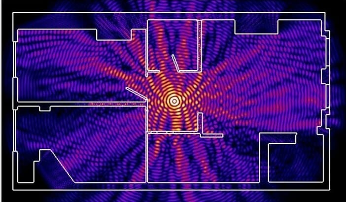
The next problem in the path of radio waves: mirrors and metal structures. Unlike walls, they do not attenuate, but reflect the signal, scattering it in arbitrary directions.

Mirrors and metal structures reflect and scatter the signal, creating dead zones behind them.

If you move the elements of the interior that reflect the signal, it will be possible to eliminate the dead zones.
In practice: It is extremely rare to achieve ideal conditions when all gadgets are in direct line of sight with a router. Therefore, in a real home, you will have to work separately to eliminate each dead zone:
- find out what interferes with the signal (absorption or reflection);
- think over where to move the router (or piece of furniture).
Place the router away from sources of interference
The 2.4 GHz band does not require licensing and therefore is used for the operation of consumer radio standards: WiFi and Bluetooth. Despite its low bandwidth, Bluetooth can still interfere with the router.
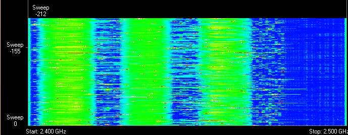
Green areas - stream from WiFi router. Red dots are Bluetooth data. The proximity of two radio standards in the same range causes interference, which reduces the range of the wireless network.
The magnetron of the microwave oven emits in the same frequency range. The radiation intensity of this device is so great that even through the protective screen of the oven, the radiation of the magnetron is able to “light up” the radio beam of the WiFi router.
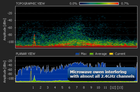
Microwave oven magnetron radiation causes interference on almost all WiFi channels.
On practice :
- When using Bluetooth accessories near the router, turn on the AFH parameter in the settings of the latter.
- The microwave is a powerful source of interference, but it is not used as often. Therefore, if it is not possible to move the router, then it will simply not be possible to make a Skype call while preparing breakfast.
Disable support for 802.11 b / g modes
WiFi devices of three specifications work in the 2.4 GHz band: 802.11 b / g / n. N is the latest standard and offers greater speed and range than B and G.

The 802.11n (2.4 GHz) specification provides longer range than the legacy B and G standards.
802.11n routers support previous WiFi standards, but the mechanics of backward compatibility are such that when a B / G device, such as an old phone or a neighbor's router, appears in the N router's area, the entire network is switched to B / G mode. Physically, the modulation algorithm changes, which leads to a drop in the speed and range of the router.
In practice: Putting the router in “pure 802.11n” mode will definitely have a positive effect on the quality of the coverage and throughput of the wireless network.
However, B / G devices will not be able to connect via WiFi. If it's a laptop or TV, they can be easily connected to the router via Ethernet.
Choose the optimal WiFi channel in the settings
Almost every apartment today has a WiFi router, so the density of networks in the city is very high. Signals from neighboring access points overlap each other, draining energy from the radio path and greatly reducing its efficiency.

Neighboring networks operating at the same frequency create mutual interference interference, like circles on water.
Wireless networks operate within range on different channels. There are 13 such channels (in Russia) and the router switches between them automatically.
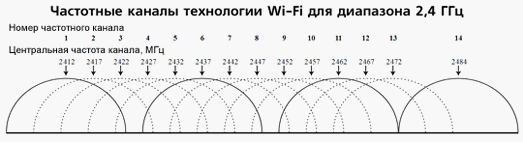
To minimize interference, you need to understand which channels the neighboring networks operate on and switch to a less loaded one.
Detailed instructions for setting up a channel are presented.

In practice: Selecting the least congested channel is an effective way to expand the coverage area, which is relevant for residents of an apartment building.
But in some cases, there are so many networks on the air that not a single channel gives a tangible increase in the speed and range of WiFi. Then it makes sense to turn to method number 2 and place the router away from the walls bordering neighboring apartments. If this does not work, then you should think about switching to the 5 GHz range (method no. 10).
Adjust the transmitter power of the router
The transmitter power determines the energy of the radio path and directly affects the range of the access point: the more powerful the beam, the further it hits. But this principle is useless in the case of omnidirectional antennas of household routers: in wireless transmission, two-way data exchange occurs and not only clients must “hear” the router, but vice versa.
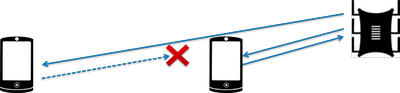
Asymmetry: the router “reaches out” to a mobile device in the back room, but does not receive a response from it due to the low power of the smartphone's WiFi module. The connection is not established.
In practice: The recommended value for the transmitter power is 75%. It should be increased only in extreme cases: the power turned 100% not only does not improve the signal quality in distant rooms, but even worsens the stability of reception near the router, since its powerful radio stream “clogs” the weak response signal from the smartphone.
Replace the original antenna with a more powerful one
Most routers are equipped with standard antennas with a gain of 2 - 3 dBi. The antenna is a passive element of the radio system and is not able to increase the flow power. However, increasing the gain allows the radio signal to be refocused by changing the directional pattern.
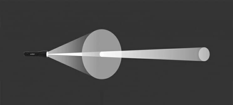
The higher the antenna gain, the further the radio signal propagates. In this case, the narrower stream becomes similar not to a “donut”, but to a flat disc.

There is a large selection of antennas for routers with a universal SMA connector on the market.


In practice: Using an antenna with a high gain is an effective way to expand the coverage area, because simultaneously with the signal amplification, the antenna sensitivity increases, which means the router begins to “hear” remote devices. But due to the narrowing of the radio beam from the antenna, dead zones arise near the floor and ceiling.
Use signal repeaters
In rooms with complex layouts and multi-storey buildings, it is effective to use repeaters - devices that repeat the signal of the main router.


The simplest solution is to use an old router as a repeater. The disadvantage of this scheme is half the throughput of the child network, since along with the client data, the WDS access point aggregates the upstream from the upstream router.
Detailed instructions for configuring the WDS bridge are presented.

Specialized repeaters are free from the problem of bandwidth cuts and are equipped with additional functionality. For example, some models of Asus repeaters support the roaming function.

In practice: No matter how complicated the layout is, repeaters will help you deploy a WiFi network. But any repeater is a source of interference. With free air, repeaters do their job well, but with a high density of neighboring networks, the use of repeater equipment in the 2.4 GHz band is impractical.
Use 5 GHz band
Budget WiFi devices operate at 2.4GHz, so the 5GHz band is relatively free and has little interference.

5 GHz is a promising range. It works with gigabit streams and has an increased capacity compared to 2.4 GHz.
In practice: “Moving” to a new frequency is a radical option that requires the purchase of an expensive dual-band router and imposes restrictions on client devices: only the latest models of gadgets work in the 5 GHz band.
The problem with the quality of the WiFi signal is not always related to the actual range of the access point, and its solution in general terms boils down to two scenarios:
- In a country house, it is most often required, in free air conditions, to cover an area that exceeds the effective range of the router.
- For a city apartment, the range of a router is usually sufficient, and the main difficulty lies in eliminating dead zones and interference interference.
The methods presented in this material will help to identify the causes of poor reception and optimize the wireless network without resorting to replacing the router or the services of paid specialists.
Found a typo? Select the text and press Ctrl + Enter
Purchase a USB wireless dongle adapter. Thanks to this finger-sized device, the computer can connect to Wi-Fi networks. You need it even if your computer already has a built-in wireless network adapter.
- For the best compatibility, buy a Wi-Fi adapter that also works with 802.11b and 802.11g standards.
- To find out the cost, visit Google Commerce or Pricewatch. Simple adapters that are reasonably effective at close range will cost around $ 15-20.
- Form matters. For best savings, choose a small, finger-shaped adapter. The large flattened mouse adapters ($ 50 - $ 60) are generally more sensitive and powerful. While they can be difficult to install, they perform better in more challenging environments.
We buy a passive USB extension cable. You need a Type A (male) to Type A (female) cable. You can purchase it at a one-stop shop, your local computer store, or online. With it, you connect the USB Wi-Fi adapter to the USB port of your computer.
- The antenna is directional, so you need to position it so that it points towards the wireless access point. Make sure the cable is long enough (maximum length 5 m) to place the antenna in the desired location.
- If necessary, multiple extension cables can be connected.
- Active USB Extenders (~ $ 10 USD) allow cable lengths over 5m so the antenna can be mounted even higher for best results.
Take a mesh colander. It is best to use Asian "scoop" type cookware (like a wok, but mesh) that is used for frying. Its shape is perfect for our purposes, and it also comes with a wooden handle!
- You can also use a strainer, steamer, pot lid and lamp shade, provided they are hemispherical and made of metal. Any parabolic mesh piece of metal will work — the larger the better the signal, although this can make installation difficult.
- For larger options, old parabolic TV antennas or a mesh umbrella frame will do. Although they will give more signal gain, installation and drag problems can occur, so a 300mm diameter seems to be the most practical.
- The flexible leg from the table lamp will allow you to neatly position and direct your antenna.
Putting the system together. Use wire, tape, or hot glue to attach the Wi-Fi adapter and USB extension cable to the plate.
- The adapter should be installed in the center of the "hot spot" of the dish - radio signals hit the dish and are reflected in the center with a few fingers above its surface.
- The best location for the adapter can be determined with a simple experiment. One method is to cover the dish with aluminum foil to determine how sunlight is reflected in it - the most illuminated point is the focal point of the dish.
- You may need a small rod to secure the adapter in the desired position.
- Alternative ways of securing: Use a string tied around the front of a spider web plate, scraped-out plastic garden hose fittings, or even chopsticks!
Antenna connection. Plug one end of the USB extension cable (male) into your computer, and in the network settings, configure it as a Wi-Fi adapter.