There are many reasons why some people want to make their own subwoofer. The most important of them is the ability to customize the speaker to certain parameters and save money. WITH in cash and so everything is clear, but with setting up the subwoofer it’s not so simple. During the design and assembly of a subwoofer, tuning a subwoofer means calculating the body (box, drawer) of the subwoofer and selecting the speaker.
In this article I will try to cover as much as possible more programs for subwoofer calculations, which will help you decide on the type of speaker and cabinet design for your subwoofer.
Professional subwoofer calculation program
BassBox Pro 6
Let's start with the most famous program about which I am. This is a program that is designed for modeling and testing acoustic systems. Recently, complex formulas and nomograms were used to calculate the parameters of acoustic systems... Also, often these formulas were greatly simplified, or some data was missing, as a result of which the actual results could differ very significantly from the calculated version. Everything had to be re-calculated and redone. Nowadays, the situation has changed significantly: many programs have been created designed to simulate acoustics on personal computer. The BassBox Pro 6 program proposed in this review belongs to such programs.
Bass Port


Extremely powerful system analysis sound signals- both recorded and in real time.
The analysis is carried out in three main modes: Real Time - processing and plotting in real time based on data coming from the audio port; Recorder - the same, with parallel recording of the incoming signal; Post-Processing - analysis of a pre-recorded Wave file.
The analysis results are dynamically presented in several windows:
* Time Series - regular waveform
* Spectrum - spectral graph, continuous or strip
* Phase - changes in signal phase
* Spectrogram - a graph of changes in the spectrum over time, in which instantaneous “snapshots” of the signal spectrum are drawn vertically with colored lines
* 3D Surface - three-dimensional spectrogram
All kinds of windows can be opened and dynamically updated simultaneously.
Scalar results are also displayed - frequency and amplitude of peaks, signal power, harmonic coefficient, intermodulation coefficient, signal-to-noise ratio.
There is a test signal generator, also operating in real time, with which you can analyze the operation of the audio path under study.
The program has a large number of parameters specifying frequency bands and analysis methods, Fourier transform parameters, window functions, displayed graphs, etc. This is probably the most powerful signal analysis system for PC.
Subwoofer calculation program
JBL Speakershop
Good luck with designing and building your subwoofer!
This program. Its main purpose is to calculate the ports for the bass reflex.
If you are interested in making your own subwoofer, Bassport will surely be useful to you.
I see your bewilderment: why was it necessary to create this program if there are others with which you can calculate not only the port, but also the entire bass reflex?
The answer is that all these programs pay little attention to port design, and in best case scenario They provide very little information about the air flow, or even none at all.
When you start designing a port, you inevitably have a question: what to start from? How big should the port be? Which form is better? What should be the distance from the port to the opposite wall?
Like you, I asked myself these same questions. There were no answers either in paper literature or on the Internet. It turned out that the bicycle was, as it were, invented, but they didn’t really care about the pedals, they say, they should be there, and you can attach them yourself, whichever ones you want.
On various forums, both ours and very foreign ones, someone recommended a port of half the diffuser area, someone recommended a third, someone a quarter - in a word, inconsistency, confusion and the absence of any arguments. If you make a port with a small diameter, it will make noise, and if the diameter is large, the port becomes long and does not fit into the box. Where is the golden mean, where is a reasonable compromise?
To understand this, I conducted a series of experiments with round and round ports. rectangular section different shapes: straight, conical, and hourglass-shaped. At the same time, he noted the noticeability of noise at a distance of 0.5 m from the port, and also calculated the speed air flow at the exit of the port and in its narrowest part.
Based on the results of these studies, the Bassport program was created (it didn’t take too long to come up with the name 🙂). This is a tool with which you can design good ports, getting rid of doubts like “will such a cross-sectional area work?”
The general idea is this: noise becomes noticeable if the air flow speed at the port exit exceeds 6...9 meters per second. This happened with all the ports participating in the experiments. At a speed of 6 m/s the noise was barely noticeable, but at 9 m/s it was clearly detected.
This is what the main program window looks like. There is also a help window and a database window for car audio brands, but you can easily figure them out without my tips, and we will continue.
As you can see, the interface is simple. At the very top, under the window title, is the control panel. On the left side there are five project management buttons: Create, Open, Save, Print, Delete - in a word, standard buttons.
The last of the buttons is called Calculator. It can be used to calculate the sound wavelength for required frequency, or vice versa, frequency at a given wavelength.
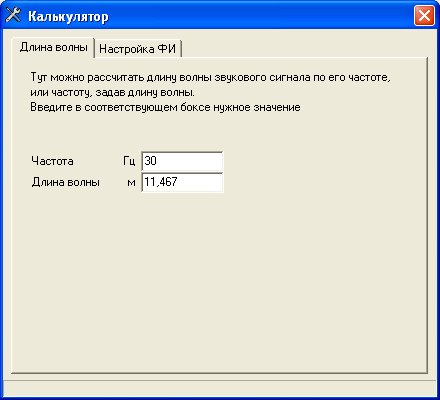
You can also determine the bass reflex setting if the working volume and port dimensions are known.

If we press the Car Audio button, we will see a list of car audio brands and can even go to the website of the selected manufacturer, of course, if by this time you have an Internet connection.

And finally, on the far right is the Help button. Before you start working with the program, use it. Well, this is my good wish, but practice suggests that at best a quarter of users click it.
How about you personally – are you among the majority? 🙂
Rest working space The main window is divided into two parts: upper and lower.

Top part: here we enter the data.

The lower part... we also enter some things, and then click the Recalculate button.
On the right are gray fields where the calculation results are displayed. Let's see what's there.
The first thing we notice is that the results are displayed in two columns: for the neck and for the outlet port. If the port is simple, then the values in both columns will be the same, and if the port complex shape, then they will differ.
Secondly, all values are given for one port, even if you set the number of ports to more than one. This is so that you don’t get confused and don’t subtract or multiply anything. As shown on the screen, we cut such a port in the required quantity. Two is two. Five is five. There is no need to do any recalculations either in your head, or on paper, or, God forgive me, in Excel.
That's all, actually.
Oh yes. At the bottom left we see several buttons that allow you to select the shape of the port. As shown by the turbulent everyday life, most often people use buttons 1, 5 and 6. Play with them yourself, see what happens.
![]()
That's all for sure now. Now you have good tool for designing ports, and even with a Russian-language interface.
How, not yet? Then urgently find the heading "Get Bassport" on the right side of the page, enter your name and e-mail, confirm your subscription - and you will receive a download link.
Enjoy it for your health. And if the capabilities of this program begin to be missed, pay attention to a more advanced version, . It's paid, but I think you won't be disappointed.
The characteristics of the box (bass reflex) directly affect the sound of the speaker. In car acoustics, this is often not given due attention, they use the principle - the larger the speaker in the box, the better. The phase inverter requires careful tuning, and not the use of improvised materials. Those who are too lazy to do calculations and measurements use a closed box.
To calculate the bass reflex, use simulation programs (Bass Port), but to get the result, you need to enter many parameters. And even if you know them, you often get a big discrepancy with the final result. With help simple method phase inverter calculation, you do not need to know the data for your speakers, boxes, without complex mathematical calculations And measuring instruments. The technique has existed for 30 years, the error is only 5%.
Phase inverter differences
Every speaker has a resonant frequency. When operating above this indicator, good sound is obtained, and below this, the pressure level drops by 12 dB per octave (frequencies are reduced by 2 times). The lower level of reproducibility is considered to be 6 dB. By installing the speaker in a box, the resonant purity increases due to the additional elasticity of the air. Increasing the resonant frequency pulls up and the lower limit. The less air in the box, the better the elasticity and the higher the performance.
You can make a “big box” without increasing its size. For this use material with damping properties(cotton wool). The more of it there is in the box, the lower the frequency of the speaker. But when there is too much filler, it has the opposite effect. For inexperienced people, the quality of the box and its size are not important. In most cases, the column size is optimal.
A bass reflex is a pipe, not necessarily round, of a certain length, which has resonance. Thanks to the “second resonance”, the sound output of the speaker increases. The vibration frequency of the speaker in the box should be lower than in the normal state. Thus, the decline is compensated and the sound expands. These indicators for a bass reflex will be 24 dB higher than for a buried box. It extends the low end frequencies of the speaker.
To avoid barrel sound, resonance indicators should not be higher than that of closed box. And if the frequency is too low, the speaker's performance drops. This is the essence of adjusting the bass reflex in order to get a positive effect and not spoil the sound. And you can achieve it at home good sound with an error of 5%.
Phase inverter calculation
At resonance, the resistance of the voice coil increases. To measure, a resistor is connected in series to the speaker, the value of which is higher than the speaker resistance by an order of magnitude, from 100 to 1000 Ohms. By measuring voltage, you can estimate the resistance of the voice coil. At frequencies where there is high resistance, the voltage across the resistor is minimal and vice versa.
Absolute values are not important to us, only the maximum resistance on the coil (minimum on the resistor). To do this we will use a multimeter in metering mode AC voltage . As a source, professionals use an audio frequency generator. And for our task, a special CD is suitable.
The measurement process looks like this:
- The bass reflex hole is plugged with a piece of plywood.
- The disc with recordings of audio frequencies is turned on at an acceptable volume.
- Switching between tracks, we monitor the voltage on the resistor, as soon as it jumps to a minimum, that’s the desired frequency.
By the way, the optimal volume of filler for the speaker is selected, gradually adding a small amount and monitoring the fluctuations in the resonant frequency. And having found this parameter, you need it multiply by 0.63, and you get the required frequency for the bass reflex. But we still need to measure the length, for this we open the hole, turn on the test disk with the recording. And look at the resistor reading. But now we are looking not for the minimum resistance, but for the maximum. The bass reflex frequency will be very different from the desired one. To increase it, shorten the long tunnel or increase its diameter.
Calculation of indicators using the Bass Port program
The program interface is simple and clear, all fields and settings are signed.
Necessary enter these parameters:
Calculation of the bass reflex according to the methodology of the magazine "Radio"
Assembling a circuit with a generator audio frequency and a 1000 Ohm resistor, it is not recommended to take less power. We place the speakers away from the ceiling and walls. Connect a voltmeter and measure the voltage at 500 Hz. And we find the maximum (Fs) and minimum indicators (Us). To find out the required volume of the box (V), we take the same size box with a hole for the speaker, but not made of cardboard. We install the speaker and seal all the holes. We carry out measurements and calculate Fs. We substitute the obtained data into the formula: Vas = ((Fs ’/ Fs)^2-1)* V.
To configure the bass reflex, close the tunnel hole and calculate maximum rate(Fs), add sound-absorbing material and measure again. We add the obtained result into the formula Fb = 0.63* Fs. The length of the tunnel is calculated: LV= 31*10^3* S /(Fb ^2* V), where S is the area of the phase inverter port (in cm²) and V is the volume of the box (in liters).
The bass reflex directly affects the sound quality of the acoustics. There are several methods for calculating a phase inverter, they have the same first stage - measuring indicators. Usage software, often gives the wrong result. You can also use online services but they have the same disadvantages.
Video: how to calculate round phase inverter ports
Fans of good acoustic sound know that its quality primarily depends on the transmission of the low-frequency component of sound. Using a bass reflex can significantly increase the level sound pressure at the same power input. But all this is possible only with the correct calculation of the dimensions of the bass reflex (FI) hole, leveling harmonic vibrations and providing high-quality sound.
Types of acoustic systems
Sound is a vibration of mechanical origin, propagating under pressure caused by a radiation source. Acoustic system, which is speaker, converts electrical signals into mechanical ones, perceived by human hearing. The frequency of these oscillations ranges from 20 Hz to 20 kHz. Exist different kinds acoustic systems:
The use of a phase inverter type makes it possible not only to expand the lower frequency range, but also increase the coefficient useful action. In this case, the frequency range will not change. The bass reflex hole is made different types and sizes. It can be placed on any surface of the column. When developing an acoustic system, it is most important to correctly calculate the size of the bass reflex box, which determines not only the range of reproduced frequencies, but also the quality of the entire sound as a whole.
How the device works
Any bass reflex type speaker has a hole - a bass reflex. This is often called an acoustic tunnel or port. Its operating principle is to change the phase of the sound vibration caused by the rear side of the diffuser by one hundred and eighty degrees. When resonance occurs in the box, the vibration amplitude of the diffuser reaches a minimum value.
This is due to the fact that when moving forward, the speaker creates a vacuum in the middle of the closed column, thereby displacing air into the bass reflex channel and increasing the vacuum. Therefore, at the resonance frequency, mechanical waves are emitted through the hole, and not from the speaker cone.
The volume of air and the resonance frequency to which the channel is tuned depend on the size and type of the bass reflex port. The volume of air in the channel begins to resonate and enhance frequency reproduction when the moment comes when the diffuser emits the frequency for which the bass reflex is designed.
The classic tunnel is circular in shape. But to increase the useful internal area, it is often given a slotted appearance. Refusal of the cylindrical shape of the tunnel makes it possible to reduce its length and reduce the noise that occurs when air is released.
If there are errors in the calculation of a slotted phase inverter, it is much more difficult to configure it than classic look, since it is manufactured together with the column. The calculation itself is more complicated than for systems closed type: in this case, in addition to the volume of the box, the adjustable resonance frequency is taken into account. Optimal sizes are selected taking into account the amplitude-frequency characteristics of the speaker, namely its uniformity.
Low frequency tunnel calculation
There are several ways to calculate FI sizes. The most popular is to calculate the bass reflex online or using specialized programs. Such methods usually require knowledge of many parameters of the speakers used. There are simpler options, but with a large discrepancy between the final result and the real value. Although in any case, after calculation and manufacturing, adjustments have to be made.
Simple formula to calculate
The calculation method involves the use of simple formulas and is carried out using the data selection method, when the desired length of the FI channel is used as a basis.
F = (C/2 π) * K, where:
In this case, the coefficient K is equal to square root S/LV ratios, where:
- S - hole area;
- L - channel length;
- V is the volume of the column.
Meters are used everywhere as units of measurement, and hertz is used for frequency. When determining volume values, it is believed that it is better to choose a narrow bass reflex, but this approach is incorrect, because at the same time the speed of air movement in it increases, and this introduces distortion into the sound. Designing a wide and long FI is also meaningless, because the length of the bass reflex should not exceed the wavelength at the moment of resonance. Following this rule helps to get rid of standing waves.
Using specialized programs
A strip cut from whatman paper, the width of which coincides with the length of the tube, is wound in several turns on the surface of newsprint. In this case, epoxy glue is applied before each turn. It is obtained by mixing resin and hardener according to the instructions. After all the turns have been completed, the product is wrapped in a circle with thread to impart rigidity and placed to dry.
 After a day, the base is removed. If difficulties arise, it can be broken from the inside and taken out in parts. A manufactured channel of this type has good strength and is easily subjected to additional processing. Next, the resulting tube is installed in the hole of the speaker, but not all the way, and listening to the sound begins. In the factory, a special device is used. Such a device operates on the basis of a multivibrator, which is tuned to the resonant frequency of the dynamic head. After connecting the speaker, the generator starts and the length of the pipe is adjusted to the maximum fluctuation of air in it.
You can do the same setup yourself. To do this, a low frequency signal is supplied to the input. The tube is moved forward or immersed inside the box, and then the volume of escaping air is assessed. Having established the position of its maximum outlet, the excess pipe is removed from the outside, and the port itself is sealed. If desired, to give the structure a finished look, open the pipes, but you can do without it.
Conclusions on the problem of “port construction”
This is what emerged from the results of writing a program for calculating ports.
1. Increasing the number of ports
1.1. If the total area of the ports remains unchanged, then with an increase in the number of ports their length increases slightly, which in the limit tends to 1.57 times the length of the original single port.
1.2. If the area of the ports increases, we obtain a decrease in the speed of fluctuations of the air mass in the ports and a decrease in noise effects.
2. Port length saving
It is hardly possible to give clear unambiguous recommendations here.
The user will have to decide for himself what type of port and with what parameters to choose, based on what is more important: the gain in length, or silent operation port.
Starting from version 0.6beta, to calculate the minimum allowable port area, different values maximum speed, depending on the port type.
Ports are always noisy. Most often, these noises are masked by a useful signal, but sometimes they become very noticeable and very unpleasant.
Each port is “noisy” in its own way, and the noise threshold is also individual for each port.
Based on experimental data, the program introducedindicativeair flow rates:
– noticeable at distances of 0.2...1 m (displayed purple)
– noticeable at distances greater than 1 m (displayed in red)
When designing a port, in the result windows you will see to what extent the given port will be “noisy”.
3. Port geometry
3.1. A simple port has two significant shortcomings:
– organ resonances (at least two)
– increased turbulence at the edges of the port.
To eliminate these shortcomings, ports with an indirect generatrix are used.
3.2. Such ports make it possible to reduce the cross-sectional area of the port neck, and thereby reduce its length. At the same time, the air flow speed in the narrow part of the port increases, and at the edges it decreases due to an increase in the exit area. Organ resonances shift to the side high frequencies or disappear completely.
4. Conditions for choosing a particular type of port
4.1. Simple tubular port. Can be used if the air flow speed in it does not exceed 6-9 m/s. If the port is placed on the rear wall, organ resonances will be heard less. True, at the same time back panel The speaker should not be located too close to the wall.
If you round the edges of such a port, you can achieve some noise reduction. Starting from version 0.4beta, the program has added the ability to calculate ports with rounded edges.
4.2. Conical port. There are no organ resonances at all. We get the most “musical”, but also the longest port. The air flow speed in the narrow part should also not exceed 6-9 m/s.
4.3. Pipe-cone port (“funnel”). Symbiosis of cone and pipe. FrequentlyO You organ resonances are located higher than for a trumpet, and become less noticeable, but do not disappear completely. We get a significant saving in length compared to a cone.
At the narrow end of the port, the flow speed should not exceed 9-12 m/s.
4.4. Cone-pipe-cone port (“hourglass”). FrequentlyO You organ resonances shift even more upward, the visibility drops even more. Length saving, all other things being equal, is slightly worse than in the case of a “funnel”. But the air speed in the throat can be increased by reducing the diameter of the pipe, which will lead to a decrease in the length of the port. The air flow speed should not exceed 13-16 m/s.
4.5. Port of a smooth curved generatrix. Organ resonances are absent as a class. The saving of length is slightly worse than in the case of the hourglass.
Starting from version 0.5beta, the ability to calculate ports with a curvilinear generatrix has been added to the program.
The air flow speed should also not exceed 13-16 m/s
To better understand, experiment with the calculations, a lot will become clearer.
Good luck!