| AT + CMGR = 3.0 | Over the past decade, car thefts have occupied one of the most important places in the structure of crimes committed in the world. This is due not so much to the specific weight of this category of theft in relation to the total number of crimes, but to the significance of the damage caused due to the high cost of cars. The weak effectiveness of the measures taken in the field of combating vehicle theft by the end of the 90s led to the creation of stable groups specializing in the commission of these crimes and having the distinctive features of organized crime; you've probably heard the term "black auto business". The car park of European countries is annually missing ≈ 2% of cars that become the subject of criminal encroachments. Therefore, I got the idea to make a gsm alarm for my car based on Arduino Uno. Let's get started!
What will we collect
We must choose the heart of our system. In my opinion, there is nothing better for such signaling than the Arduino Uno. The main criterion is a sufficient number of pins and a price. 
Key features of Arduino Uno
Microcontroller - ATmega328
Working voltage - 5 V
Input voltage (recommended) - 7-12 V
Input voltage (limit) - 6-20 V
Digital Inputs / Outputs - 14 (of which 6 can be used as PWM outputs)
Analog Inputs - 6
DC current through input / output - 40 mA
DC current for 3.3 V pin - 50 mA
Flash Memory - 32KB (ATmega328) of which 0.5KB is used for bootloader
RAM - 2 KB (ATmega328)
EEPROM - 1 KB (ATmega328)
Clock frequency - 16 MHz
Fits! Now you need to select a gsm module, because our alarm system should be able to notify the owner of the car. So, you need to google ... Here, an excellent sensor - SIM800L, the size is just wonderful.

I thought and ordered it from China. However, everything turned out to be not so rosy. The sensor simply refused to register the SIM card on the network. Everything that was possible was tried - the result was zero.
There were kind people who provided me with a cooler thing - Sim900 Shield. This is already a serious thing. The Shield has a microphone and headphone jack, a full-fledged phone. 
Main features of Sim900 Shield
4 standards of working frequency 850/900/1800/1900 MHz
GPRS multi-slot class 10/8
GPRS mobile station class B
Compliant with GSM phase 2/2 +
Class 4 (2 W @ 850/900 MHz)
Class 1 (1 W @ 1800 / 1900MHz)
Controlled by AT commands (GSM 07.07, 07.05 and SIMCOM extended AT commands)
Low power consumption: 1.5mA (sleep mode)
Operating temperature range: -40 ° C to +85 ° C
Fits! Ok, but you have to take readings from some sensors to notify the owner. Suddenly the car is evacuated, then the position of the car will obviously change in space. Let's take an accelerometer and a gyroscope. Fine. Dachshund, now we are looking for a sensor.
I think the GY-521 MPU6050 will definitely fit. It turned out that it also has a temperature sensor. It would be necessary to use it, there will be such a "killer feature". Suppose the owner of the car put it under the house and left. The temperature inside the car will change "smoothly". What happens if an intruder tries to break into a car? For example, he will be able to open the door. The temperature in the car will begin to change rapidly, as the air in the passenger compartment begins to mix with the ambient air. I think it will work.

Main features of GY-521 MPU6050
3-axis gyroscope module + 3-axis accelerometer GY-521 on the MPU-6050 chip. Allows you to determine the position and movement of an object in space, the angular velocity during rotation. It also has a built-in temperature sensor. It is used in various copters and aircraft models, it is also possible to assemble a motion capture system based on these sensors.
Microcircuit - MPU-6050
Supply voltage - from 3.5V to 6V (DC);
Gyroscope range - ± 250 500 1000 2000 ° / s
Accelerometer Range - ± 2 ± 4 ± 8 ± 16g
Communication interface - I2C
Size - 15x20 mm.
Weight - 5 g
Fits! A vibration sensor is also useful. Suddenly, they will try to open the car with "brute force", or, in the parking lot, another car will touch your car. Take the vibration sensor SW-420 (adjustable).

Main features SW-420
Supply voltage - 3.3 - 5V
Output signal - digital High / Low (normally closed)
Used sensor - SW-420
Comparator used - LM393
Dimensions - 32x14mm
Additionally - There is an adjusting resistor.
Fits! Screw on the SD memory card module. We will also write a log file.

Main characteristics of the SD memory card module
The module allows you to store, read and write to the SD card the data required for the operation of the device based on the microcontroller. The use of the device is relevant when storing files from tens of megabytes to two gigabytes. The board contains an SD card container, a card power stabilizer, a plug for the interface and power lines. If you need to work with sound, video or other volumetric data, for example, to keep a log of events, sensor data or store information from a web server, then the SD memory card module for Arduino will make it possible to use an SD card for these purposes. Using the module, you can study the features of the SD card.
Supply voltage - 5 or 3.3 V
SD card memory capacity - up to 2 GB
Dimensions - 46 x 30mm
Fits! And let's add a servo, when the sensors are triggered, the servo with a video recorder will turn and shoot video of the incident. Take the MG996R servo.

Main features of MG996R servo
Stable and reliable protection against damage
- Metal drive
- Double row ball bearing
- Wire length 300 mm
- Dimensions 40x19x43mm
- Mass 55 gr
- Angle of rotation: 120 degrees.
- Working speed: 0.17sec / 60 degrees (4.8V no load)
- Working speed: 0.13sec / 60 degrees (6V no load)
- Starting torque: 9.4kg / cm at 4.8V power supply
- Starting torque: 11kg / cm at 6V power supply
- Working voltage: 4.8 - 7.2V
- All drive parts are made of metal
Fits! We collect
There are a lot of articles about connecting each sensor in Google. And I have no desire to come up with new bicycles, so I will leave links to simple and working options. You can also send SMS - messages, all you need is a special Arduino GSM / GPRS SIM900 module. This expansion board fits the common Arduino UNO, MEGA and Leonardo boards. With its help, you can make a bunch of different projects using GPRS Internet or access to the GSM network. It will work wherever there is a mobile network. Using this module, you can make a GSM alarm system, which, together with a video surveillance system, will provide excellent protection for your home.
The module allows using networks of standards GSM 850, GSM 900, GSM 1800, GSM 1900 and supports TCP protocol with access to the GPRS network.
Arduino GSM the SIM900 module can also be used to make calls, you can both receive calls and make them. To do this, the board has special connectors for connecting a microphone and a speaker. You can also connect the module to a computer and send and receive data directly from the PC. For example, you can do mass mailing to subscribers recorded on a sim card in an automatic mode.
Features of connecting the GSM board to the Arduino Leonardo and Arduino Mega boards
The GSM extension board works with Arduino directly thanks to the Software Serial library. With standard settings, digital pins No. 2 and No. 3 are connected for the modem to interact with the Arduino. These settings are suitable for the Arduino Uno, but for the correct operation of the shield on the Arduino Leonardo or Arduino Mega, it is necessary to make corrections.
GSM_TX pin, also called pin # 2 on the expansion board, sends information to Arduino. In order to know exactly at what moment it is necessary to read information, Arduino uses an interrupt mechanism: when the digital signal level changes, a corresponding interrupt occurs in this pin. However, in Arduino Leonardo and Arduino Mega pin # 2 does not support interrupts.
For the shield to function normally on the Arduino Mega or Leonardo, you do not need to change the program code at all, the library itself changes the number of the RX pin of the Arduino when you select the correct model in the "Tools" menu of the development environment.
Arduino Leonardo

For correct functioning with Leonardo, the GSM library uses digital pin No. 8. To do this, on the GSM expansion board, connect digital pins No. 2 and No. 8 with a conductor.
On the rear side of the GSM board, bend to the side the pin corresponding to pin # 2 so that it does not come into contact with the Arduino Leonardo.
Arduino Mega2560
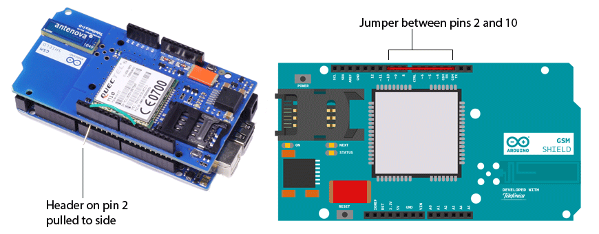
The GSM library for the correct robots with Mega uses digital pin No. 10. On the GSM expansion board, it is necessary to close digital pins No. 2 and No. 10 with a conductor, as with Arduino Leonardo. Do not forget to bend at the same time from the back side of the GSM board towards the pin corresponding to pin No. 2, so that it does not touch the Arduino Mega.
Arduino is a hardware platform used to quickly create a variety of electronic devices, including security ones. Thanks to the simple design, simplicity of the programming language, as well as the use of open codes, even a non-professional can independently make a multifunctional alarm to guard his house, summer cottage, apartment or garage. The Arduino GSM module will be the best option for creating a budget security system that can be optimally configured for a specific object.
Application area
The Arduino hardware platform is widely used in the process of creating various electronic systems and devices that can receive and process signals from variously functional analog or digital sensors and sensors. The results of processing the received signals can be used to control external actuators and systems connected to the Arduino.
An example of using these modules in the video:
Appointment
The Arduino hardware platform makes it possible to effectively interact with the controlled environment through a wide range of functional sensors that can monitor various parameters. Thanks to this, on the basis of such platforms, it is possible to form security complexes that will monitor movements along the protected perimeter, the opening of windows and doors, and damage to glass. In addition to security sensors, temperature sensors, water or gas leakage control sensors can also be used.
Using the Arduino GSM module with the platform, information about a hazard or an emergency situation at the facility can be delivered to the owner as quickly as possible. For this purpose, one of the networks of mobile operators is used.
A distinctive feature of Arduino devices is that their microcontroller can be programmed by the user using the Arduino language based on Wiring. Thanks to this, everyone can program the algorithm for the operation of the created burglar alarm as required for a specific protected object and the peculiarities of its application.
Benefits of using
Today there are many hardware platforms and microcontrollers that can receive information from external sensors, process it and send control signals to executive systems. The Arduino platform simplifies the implementation of the listed processes as much as possible and has a wide range of advantages over other devices of this kind.
- Low cost. The platforms are fairly cheap devices compared to their counterparts, which in no way affects their functionality.
- Cross-platform. Arduino software works effectively under such operating platforms as Windows, Linux, Macintosh-OSX.
- Ease of programming. To configure microcontrollers, the Processing programming environment is used. It is ideal for both professional and inexperienced users who work with Arduino devices.
- Upgradeability. Specialized software Arduino is open source, which allows experienced users to adapt it to specific requirements.
High reliability of the hardware platform. Arduino boards are available with ATMEGA8 and ATMEGA168 microcontrollers (earlier models) and with ATmega32u4, Atmel ATmega328 controllers (newer models), which are highly functional and reliable.
Principle of operation
To ensure the full-functional operation of security systems or other devices built using Arduino platforms, you need to have a GSM module for Arduino. It can be used to access the Internet, make voice calls or send SMS messages.
The GSM-board uses a special M10 radio modem, interaction with which is provided by special AT commands. The exchange of information with the modem is implemented using a software serial interface that owns digital codes.
The GSM modem used in Arduino is a 4-band modem that can operate on the following frequencies: GSM 850MHz and 900MHz, PCS1900MHz and DCS1800MHz. The modem supports protocols such as TCP / UDP and HTTP, which provide connections via GPRS. The transmission speed of information packets in this mode will be about 90 kbps.
Sending SMS via Arduino and GSM module is implemented if there is an installed SIM-card of one of the cellular operators. "
In addition, it will be possible to transmit voice messages, make calls - this requires an additional microphone and an external speaker. Installing a SIM card will allow the Arduino to be used in cellular or GPRS mode.
How to connect modules to arduino
Before connecting the GSM module to the Arduino, a suitable SIM card of one of the mobile operators must be installed in its slot. After that, the module is connected to the Arduino hardware platform in accordance with the instructions and its firmware is performed. For this purpose, a PC is used, which is connected to the device using a USB cable. After loading the Arduino environment, press the Upload button, which will start the software upload process. Upon completion of this process, the platform can be disconnected from the computer and powered by an external power system.
Comparative characteristics of GSM modules
The consumer market has a wide selection of different GSM modules for Arduino. Below are the main characteristics of the most popular ones.
Neoway M590
Arduino GSM module M590 is a wireless communication device used to receive and transmit information in mobile networks. The module of this series is created on a board with minimal strapping and is positioned as a GSM module for the Arduino hardware platform.

Using this device, you can establish mobile communication with an external phone, send SMS messages, exchange information according to the GPRS Class-10 standard. The module of this design does not have a microphone input, which limits the ability to receive voice communication - a connection can be established, but sound will not be transmitted.
The M590 is controlled by AT commands via serial communication. Frequencies from 900 MHz to 1800 MHz are used as working radio frequencies. The supply voltage is in the range of 3.3 ... 5 V. Therefore, the Neoway M590 GSM module is connected to the Arduino through a special voltage converter 5 V "3.3 V.
GSM module SIM800L
Compact Sim800l GPRS GSM module refers to devices that are used to support mobile communications. The module is built on the SIM-800L meringue, created by SIMCom Wireless Solutions and is designed to provide services to the services of information networks GPRS \ GSM, using frequencies from 850 MHz to 1900 MHz. It can be used to send SMS messages, make calls, and exchange information via GPRS channels.

The GSM module is completed with an antenna; if you need to improve the signal level, you can use additional antennas. To control the module, a PC can be used, connected via a special board for converting USB-UART interfaces, or directly through the UART itself. If using Sim800l GPRS GSM module ,
connection to Arduino must be implemented through a logic level converter. This is due to the fact that in SIM800L the voltage value at a logic high level is 2.8 V, and in Arduino - 3.3 ... 5 V.
GPRS Shield by Seeed Studio
Connecting the GSM module to the Arduino will provide the ability to use GSM / GPRS data exchange technologies, as well as make calls and send SMS messages. Devices of this type are built using the SIMCom SIM900 module. They have a slot for installing a SIM card, a connector for an external antenna, a set of 3.5 mm jacks for audio input and output. The Arduino GSM Shield is controlled and operated using Serial connections and a set of specialized AT commands.
This module is a special board used to control digital devices remotely, as well as to exchange information. The use of SIM900 allows Arduino to work using GSM / GPRS technologies, providing voice communication, sending SMS and data exchange using cellular and mobile networks.

For the operation of this module, a control controller, a power source, an antenna are connected to it, and a SIM card of a mobile operator is also installed. Using special jumpers, the method of data exchange with the controller is configured. If necessary, you can connect a speaker and microphone.
Top related articles