The current in the circuit flows through the conductors to the load from the source. Copper is most often used as such elements. A circuit can have multiple electrical receivers. Their resistances vary. In an electrical circuit, conductors can be connected in parallel or in series. There are also mixed types of it. The difference between each of them should be known before choosing the structure of the electrical circuit.
Conductors and circuit elements
The current flows through the conductors. It follows from the source to the load. In this case, the conductor must easily release electrons.
A conductor that has resistance is called a resistor. The voltage of this element is the potential difference between the ends of the resistor, which is consistent with the direction of power flow.
Serial and parallel connection of conductors is characterized by one general principle. The current flows in the circuit from plus (it is called a source) to minus, where the potential becomes less and less, decreases. In electrical circuits, the resistance of the wires is considered to be zero, since it is negligible.
Therefore, when calculating a serial or parallel connection, they resort to idealization. This makes learning them easier. In real circuits, the potential gradually decreases when moving along the wire and elements that have a parallel or series connection.
Series connection of conductors

In the presence of a series combination of conductors, the resistances are switched on one after the other. In this position, the current strength in all elements of the circuit is the same. Conductors connected in series create a voltage in the section, which is equal to their sum on all elements.
The charges do not have the ability to accumulate at the nodes of the chain. This would lead to a change in the electric field voltage and current strength.
In the presence of a constant voltage, the current will depend on the resistance of the circuit. Therefore, when connected in series, the resistance will change due to a change in one load.
Serial connection of conductors has a disadvantage. If one of the elements of the circuit breaks down, the work of all its other components will be interrupted. For example, like in a garland. If one light bulb in it burns out, the whole product will not work.
If the conductors were connected in series in a circuit, their resistance at each point will be the same. The resistance in the sum of all circuit elements will be equal to the sum of the voltage decrease in the circuit sections.

This can be confirmed by experience. The series connection of resistances is calculated using instruments and mathematical verification. For example, take three constant resistances of known magnitude. They are connected in series and connected to a power supply of 60 V.
After that, the estimated indicators of the devices are calculated if the circuit is closed. According to Ohm's law, the current in the circuit is found, which will determine the voltage drop in all its sections. After that, the results are summed up and the total value of the decrease in resistance in the external circuit is obtained. The series connection of resistances can be confirmed approximately. If we do not take into account the internal resistance created by the energy source, then the voltage drop will be less than the sum of the resistances. By means of instruments it can be seen that the equality is approximately observed.
Parallel connection of conductors
When connecting conductors in series and in parallel, resistors are used in the circuit. Parallel connection of conductors is a system in which some ends of all resistors converge to one common node, and the other ends to another node. More than two conductors converge at these locations.

With this connection, the same voltage is applied to the elements. Parallel sections of a chain are called branches. They run between two nodes. Parallel and serial connection have their own properties.
If there are branches in the electrical circuit, then the voltage on each of them will be the same. It is equal to the voltage on an unbranched section. At this point, the current strength will be calculated as the sum of it in each branch.
A value equal to the sum of the indicators inverse to the branching resistances will also be inverse to the resistance of the parallel connection section.
Parallel connection of resistors
Parallel and series connection differ in the calculation of the resistances of its elements. When connected in parallel, the current forks. This increases the conductance of the circuit (decreases the total resistance), which will be equal to the sum of the conductance of the legs.
If several resistors of the same value are connected in parallel, then the total resistance of the circuit will be less than one resistor as many times as they are included in the circuit.
Serial and parallel connection of conductors has a number of features. In parallel connection, the current is inversely proportional to the resistance. The currents in the resistors are independent of each other. Therefore, turning off one of them will not affect the work of the others. Therefore, many electrical appliances have exactly this type of connection of circuit elements.
Mixed
Parallel and series connection of conductors can be combined in the same circuit. For example, elements connected in parallel with each other can be connected in series with another resistor or a group of them. This is a mixed compound. The total resistance of the circuits is calculated by separately adding the values for the parallel-connected unit and for the series connection.

Moreover, first the equivalent resistances of the elements connected in series are calculated, and then the total resistance of the parallel sections of the circuit is calculated. Serial connection takes priority in calculations. These types of wiring diagrams are quite common in various devices and equipment.
Having familiarized yourself with the types of connection of circuit elements, you can understand the principle of organizing circuits of various electrical devices. Parallel and serial connection have a number of features of the calculation and functioning of the entire system. Knowing them, you can correctly apply each of the presented types to connect the elements of electrical circuits.
The current in the electrical circuit passes through the conductors from the voltage source to the load, that is, to the lamps, devices. In most cases, copper wires are used as a conductor. Several elements with different resistances can be provided in the circuit. In the instrument circuit, conductors can be connected in parallel or in series, and there can also be mixed types.
A circuit element with a resistance is called a resistor, the voltage of this element is the potential difference between the ends of the resistor. Parallel and series electrical connection of conductors is characterized by a single principle of operation, according to which the current flows from plus to minus, respectively, the potential decreases. On wiring diagrams, the resistance of the wiring is taken as 0, since it is negligible.
Parallel connection assumes that the elements of the circuit are connected to the source in parallel and turn on at the same time. Series connection means that the resistance conductors are connected in strict sequence one after the other.
When calculating, the idealization method is used, which greatly simplifies understanding. In fact, in electrical circuits, the potential gradually decreases as you move through the wiring and elements that are included in a parallel or series connection.
Series connection of conductors
The daisy chain scheme implies that they are turned on in a specific sequence one after the other. Moreover, the current strength in all of them is equal. These elements create a total stress on the site. Charges do not accumulate in the nodes of the electrical circuit, since otherwise there would be a change in voltage and current. With a constant voltage, the current is determined by the value of the resistance of the circuit, therefore, with a series circuit, the resistance changes if one load changes.

The disadvantage of such a scheme is the fact that in the event of failure of one element, the rest also lose the ability to function, since the circuit is broken. An example would be a garland that does not work if one light bulb burns out. This is a key difference from parallel connection, in which the elements can function separately.
The sequential scheme assumes that due to the single-level connection of the conductors, their resistance at any point in the network is equal. The total resistance is equal to the sum of the voltage reduction of the individual network elements.
With this type of connection, the beginning of one conductor is connected to the end of another. The key feature of the connection is that all conductors are on the same wire without branching, and one electric current flows through each of them. However, the total voltage is equal to the sum of the voltages at each. You can also consider the connection from a different point of view - all conductors are replaced by one equivalent resistor, and the current on it coincides with the total current that passes through all the resistors. The equivalent cumulative voltage is the sum of the voltage values across each resistor. This is how the potential difference across the resistor manifests itself.
The use of a serial connection is advisable when you need to specifically turn on and off a specific device. For example, an electric bell can only ring when there is a connection to a voltage source and a button. The first rule says that if there is no current on at least one of the circuit elements, then there will be no current on the rest. Accordingly, if there is current in one conductor, it is also in the rest. Another example is a battery-powered flashlight that only shines when there is a battery, a working light bulb, and a pressed button.
In some cases, a sequential scheme is impractical. In an apartment where the lighting system consists of many lamps, sconces, chandeliers, you should not organize a scheme of this type, since there is no need to turn on and off the lighting in all rooms at the same time. For this purpose, it is better to use a parallel connection in order to be able to turn on the light in individual rooms.
Parallel connection of conductors
In a parallel circuit, the conductors are a set of resistors, some ends of which are collected in one node, and others in a second node. It is assumed that the voltage in the parallel type of connection is the same in all sections of the circuit. Parallel sections of an electrical circuit are called branches and pass between two connecting nodes, they have the same voltage. This voltage is equal to the value on each conductor. The sum of the indicators inverse to the resistances of the branches is also inverse with respect to the resistance of a separate section of the parallel circuit.

With parallel and series connections, the system for calculating the resistances of individual conductors is different. In the case of a parallel circuit, the current flows through the branches, which increases the conduction of the circuit and reduces the total resistance. When several resistors with similar values are connected in parallel, the total resistance of such an electrical circuit will be less than one resistor a number of times equal to a number.
Each branch is provided with one resistor, and the electric current, upon reaching the branch point, is divided and diverged to each resistor, its total value is equal to the sum of the currents across all resistances. All resistors are replaced with one equivalent resistor. Applying Ohm's law, the value of resistance becomes clear - in a parallel circuit, the values inverse to the resistances on the resistors are summed.
With this circuit, the current value is inversely proportional to the resistance value. The currents in the resistors are not interconnected, so if one of them is turned off, this will in no way affect the rest. For this reason, such a scheme is used in many devices.
Considering the possibilities of using a parallel circuit in everyday life, it is advisable to note the apartment lighting system. All lamps and chandeliers must be connected in parallel, in which case turning one of them on and off does not affect the operation of the other lamps in any way. Thus, by adding a switch for each light bulb to a branch of the circuit, you can turn on and off the corresponding luminaire as needed. All other lamps work independently.
All electrical appliances are connected in parallel to a 220 V power grid, then they are connected to. That is, all devices are connected independently of the connection of other devices.
Laws of serial and parallel connection of conductors
For a detailed understanding in practice of both types of compounds, we present formulas that explain the laws of these types of compounds. The power calculation for parallel and series connection is different.
With a series circuit, there is the same current strength in all conductors:
According to Ohm's law, these types of conductor connections are explained differently in different cases. So, in the case of a sequential circuit, the voltages are equal to each other:
U1 = IR1, U2 = IR2.
In addition, the total voltage is equal to the sum of the voltages of the individual conductors:
U = U1 + U2 = I (R1 + R2) = IR.
The total resistance of an electrical circuit is calculated as the sum of the active resistances of all conductors, regardless of their number.
In the case of a parallel circuit, the total voltage of the circuit is the same as the voltage of the individual elements:
And the total strength of the electric current is calculated as the sum of the currents that are available along all conductors located in parallel:
To ensure the maximum efficiency of electrical networks, it is necessary to understand the essence of both types of connections and apply them expediently, using laws and calculating the rationality of practical implementation.
Mixed connection of conductors
Series and parallel resistor connections can be combined in one wiring diagram if required. For example, it is allowed to connect parallel resistors in series or a group of them, this type is considered combined or mixed.

In this case, the total resistance is calculated by summing the values for the parallel connection in the system and for the series. First, it is necessary to calculate the equivalent resistances of the resistors in the series circuit, and then the elements of the parallel. Serial connection is considered a priority, and circuits of this combined type are often used in household appliances and appliances.
So, considering the types of conductor connections in electrical circuits and based on the laws of their functioning, one can fully understand the essence of the organization of the circuits of most household electrical appliances. With parallel and series connections, the calculation of resistance and current is different. Knowing the principles of calculation and formulas, you can competently use each type of circuit organization to connect the elements in the optimal way and with maximum efficiency.
In many electrical circuits, we can find consistent and. The circuit designer can, for example, combine several standard value resistors (E-series) to obtain the required resistance.
Series connection of resistors Is a connection in which the current flowing through each resistor is the same, since there is only one direction for the current to flow. At the same time, the voltage drop will be proportional to the resistance of each resistor in the series circuit.
Series connection of resistors

Example No. 1
Using Ohm's law, it is necessary to calculate the equivalent resistance of a series of series-connected resistors (R1, R2, R3), as well as the voltage drop and power for each resistor:

All data can be obtained using Ohm's law and for better understanding are presented in the form of the following table:

Example No. 2
a) without connected resistor R3
b) with the connected resistor R3

As you can see, the output voltage U without load resistor R3 is 6 volts, but the same output voltage when R3 is connected becomes only 4 V. Thus, the load connected to the voltage divider provokes an additional voltage drop. This undervoltage effect can be compensated for by using a fixed resistor instead of a fixed resistor, which can be used to correct the voltage across the load.
Online calculator for calculating the resistance of series-connected resistors
To quickly calculate the total resistance of two or more resistors in series, you can use the following online calculator:
Summarize
When two or more resistors are connected together (the terminal of one is connected to the terminal of the other resistor), then this is a series connection of the resistors. The current flowing through the resistors has the same value, but the voltage drop across them is not the same. It is determined by the resistance of each resistor, which is calculated according to Ohm's law (U = I * R).
Did you know,
what is a thought experiment, a gedanken experiment?
This is a non-existent practice, an otherworldly experience, the imagination of what is not in reality. Thought experiments are like waking dreams. They give birth to monsters. Unlike a physical experiment, which is an experimental test of hypotheses, a "thought experiment" trickeryly replaces experimental verification with desired, untested in practice conclusions, manipulating logical constructions that actually violate logic itself by using unproved premises as proven ones, that is, by substitution. Thus, the main task of applicants for "thought experiments" is to deceive the listener or reader by replacing a real physical experiment with his "doll" - fictitious reasoning on parole without physical verification itself.
Filling physics with imaginary, "thought experiments" led to the emergence of an absurd surreal, confused and confused picture of the world. A true researcher must distinguish such "candy wrappers" from real values.
Relativists and positivists argue that the "thought experiment" is a very useful tool for testing theories (also appearing in our minds) for consistency. In this they deceive people, since any verification can only be carried out by a source independent of the object of verification. The applicant of the hypothesis himself cannot be a test of his own statement, since the reason for this statement itself is the absence of contradictions in the statement visible to the applicant.
We see this on the example of SRT and GRT, which have turned into a kind of religion that governs science and public opinion. No amount of facts that contradict them can overcome Einstein's formula: "If a fact does not correspond to the theory, change the fact" (In another version, "- The fact does not correspond to the theory? - So much the worse for the fact").
The maximum that a "thought experiment" can claim is only the internal consistency of the hypothesis within the framework of the applicant's own, often by no means true, logic. This does not test the suitability of practice. This test can only take place in a valid physical experiment.
An experiment is an experiment in that it is not a refinement of thought, but a test of thought. A thought that is self-consistent within itself cannot verify itself. This is proven by Kurt Gödel.
Parallel and serial connection of conductors - methods of switching an electrical circuit. Electrical circuits of any complexity can be represented by means of these abstractions.
Definitions
There are two ways to connect conductors, it becomes possible to simplify the calculation of a circuit of arbitrary complexity:
- The end of the previous conductor is connected directly to the beginning of the next - the connection is called serial. A chain is formed. To turn on the next link, you need to break the electrical circuit by inserting a new conductor there.
- The beginnings of the conductors are connected by one point, the ends - by another, the connection is called parallel. A bundle is usually called a branching. Each individual conductor forms a branch. Common points are called nodes of the electrical network.
In practice, a mixed connection of conductors is more common, some are connected in series, some in parallel. You need to break the chain in simple segments, solve the problem for each separately. Any complex electrical circuit can be described by parallel, serial connection of conductors. This is done in practice.
Using parallel and serial connection of conductors
Terms applied to electrical circuits
The theory acts as the basis for the formation of solid knowledge, few know how the voltage (potential difference) differs from the voltage drop. In terms of physics, an internal circuit is called a current source, which is outside is called an external one. The demarcation helps to correctly describe the distribution of the field. The current does work. In the simplest case, heat generation according to the Joule-Lenz law. Charged particles, moving towards a lower potential, collide with the crystal lattice, give up energy. Resistance heating occurs.
To ensure movement, it is necessary to maintain a potential difference at the ends of the conductor. This is called the voltage of the section of the circuit. If you just place a conductor in the field along the lines of force, the current will flow, it will be very short-lived. The process will end with the onset of equilibrium. The external field will be balanced by its own field of charges in the opposite direction. The current will stop. An external force is needed for the process to become continuous.
The current source acts as such a drive for the movement of the electric circuit. To maintain the potential, work is done within. Chemical reaction, as in a galvanic cell, mechanical forces - a hydroelectric generator. The charges inside the source move in the direction opposite to the field. The work of outside forces is being done on this. You can rephrase the above formulations, say:
- The outer part of the circuit, where the charges move, carried away by the field.
- The inner part of the circuit, where the charges move against the tension.
The generator (current source) is equipped with two poles. The one with the lower potential is called negative, the other is called positive. In the case of alternating current, the poles are continually reversed. The direction of movement of charges is inconsistent. The current flows from the positive pole to the negative pole. The movement of positive charges goes in the direction of decreasing potential. According to this fact, the concept of a potential drop is introduced:
The drop in the potential of a section of the chain is called a decrease in the potential within the segment. Formally, this is tension. It is the same for branches of a parallel circuit.
A voltage drop also means something else. The value characterizing the heat loss is numerically equal to the product of the current and the active resistance of the section. Ohm's and Kirchhoff's laws, considered below, are formulated for this case. In electric motors, transformers, the potential difference can differ significantly from the voltage drop. The latter characterizes the resistance loss, while the former takes into account the full operation of the current source.
When solving physical problems, for simplicity, the motor can include an EMF, the direction of which is opposite to the effect of the power source. The fact of energy loss through the reactive part of the impedance is taken into account. School and university physics courses differ from reality. That is why students open their mouths and listen to the phenomena that take place in electrical engineering. In the period preceding the era of the industrial revolution, the main laws were discovered, the scientist must combine the role of a theoretician and a talented experimenter. This is openly stated in the prefaces to the works of Kirchhoff (the works of Georg Ohm have not been translated into Russian). The teachers literally lured people with additional lectures, flavored with visual, amazing experiments.

Ohm's and Kirchhoff's laws in relation to serial and parallel connection of conductors
Ohm's and Kirchhoff's laws are used to solve real-life problems. The first deduced equality in a purely empirical way - experimentally - the second began by mathematical analysis of the problem, then checked the guesses with practice. Here are some information that helps to solve the problem:

Calculate the resistance of elements in series and parallel connection
The algorithm for calculating real circuits is simple. Here are some theses on the topic under consideration:
- When connected in series, resistances are summed, with parallel - conductivity:
- For resistors, the law is rewritten in an unchanged form. With a parallel connection, the total resistance is equal to the product of the original, divided by the total. With sequential - the denominations are summed up.
- Inductance acts as reactance (j * ω * L), behaves like a normal resistor. In terms of writing the formula, it is no different. Nuance, for any purely imaginary impedance, that you need to multiply the result by the operator j, the angular frequency ω (2 * Pi * f). When the inductance coils are connected in series, the ratings are summed up, when in parallel, the reciprocal values are added.
- The apparent resistance of the capacitance is written in the form: -j / ω * С. It is easy to notice: adding the values of the series connection, we get the formula, exactly as for resistors and inductors it was with parallel. The opposite is true for capacitors. With parallel connection, the denominations are added, with sequential - reciprocal values are added.
Theses are easily extended to arbitrary cases. The voltage drop across two open silicon diodes is equal to the sum. In practice, it is 1 volt, the exact value depends on the type of semiconductor element, characteristics. Power supplies are considered in a similar way: when connected in series, the ratings are added. Parallel is often found in substations, where transformers are placed in a row. The voltage will be one (controlled by the equipment), divided between the branches. The transformation ratio is strictly equal, blocking the occurrence of negative effects.
For some, the case is difficult: two batteries of different ratings are connected in parallel. The case is described by the second Kirchhoff's law, physics cannot imagine any complexity. If the values of the two sources are not equal, the arithmetic mean is taken, if we neglect the internal resistance of both. Otherwise, the Kirchhoff equations are solved for all contours. The unknowns will be currents (three in total), the total number of which is equal to the number of equations. For a complete understanding, they brought a drawing.
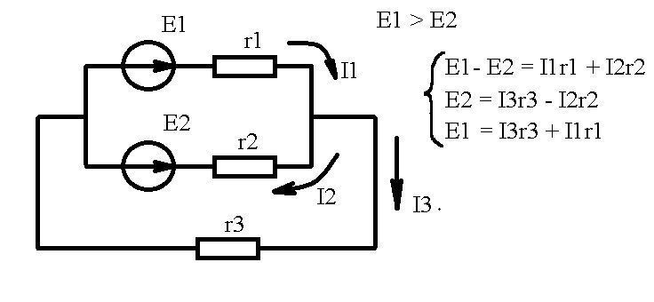
An example of solving the Kirchhoff equations
Let's see the image: according to the condition of the problem, the source E1 is stronger than E2. We take the direction of the currents in the circuit from sound considerations. But if they put it down incorrectly, after solving the problem, one would turn out with a negative sign. Then the direction had to be changed. Obviously, current flows in the external circuit as shown in the figure. We compose the Kirchhoff equations for three circuits, here is what follows:
- The work of the first (strong) source is spent on creating current in the external circuit, overcoming the neighbor's weakness (current I2).
- The second source does not perform useful work in the load, it fights with the first one. You cannot say otherwise.
Including batteries of different ratings in parallel is certainly harmful. What is observed at the substation when using transformers with different transfer ratios. Equalizing currents do no useful work. Different batteries connected in parallel will begin to function effectively when the strong one dies down to the level of the weak one.