Gradually, everyone is abandoning analog television, giving preference to digital broadcasting. The largest providers are also reorganizing to work with a newer, modern format. The era of analog TV is gradually coming to an end.
In order for the previously installed home antenna devices to finalize the resource, it is enough to connect a DVB-T receiver to the TV, as a result, digital signals will be received correctly.
You can make an antenna for digital TV with your own hands, so you don't have to go to the store and spend extra money. No special skills or equipment is required; you can create the necessary structure using available tools.
Now we will answer in detail the question of how to make an antenna for digital TV. We will carefully analyze the process, select the optimal material, and carry out all the necessary calculations. Nevertheless, let's first deal with the theoretical nuances.
Regardless of the signal format, it is transmitted from the tower's emitters. The reception of the wave channel is provided by an antenna device. To receive a digital signal, you need a sinusoidal device with the highest possible frequency, which is measured in MHz.
When an electromagnetic wave passes through the surface of the antenna's receiving beams, a V-voltage is induced in it. Each wave contributes to the formation of a different potential, marking it with its own characteristic sign.

Under the influence of the induced voltage, an electric current flows in a closed receiving circuit with a resistance R. It is gradually increasing. Processing is carried out by the TV circuit, a picture is displayed on the monitor, and the sound is transmitted through the speakers.
It will not work with a conventional indoor antenna. First, you need an intermediate link that will decode the information - a DVB-T receiver. Secondly, you should use a decimeter antenna or Turkin antenna for DVB.

Antenna figure eight
How to make such an antenna with your own hands? First you need to prepare the material. Then carry out the appropriate calculations. At the final stage, assemble the structure and connect it to the TV. Nothing complicated. Every user can cope with this task.

Antenna assembly materials
It is not difficult to make an antenna for digital television. The list of materials used will vary depending on the type of antenna device. For example, if you wish, you can make it even from the most common beer cans.
To produce a good and simple TV antenna for digital channels, copper or aluminum wire with a thickness of 2 to 5 millimeters is required. In general, it will take only 1 hour to create such a structure. You also need to use:
- a tube;
- corner;
- copper or aluminum strip.
Without fail, you will need a tool that will allow you to bend the frames of the required shape. To bend the wire, use a hammer after securing the material in a vise.

An antenna is made with your own hands, not only from wire, but also from a cable (coaxial). Match the plug to the socket on your TV. Naturally, you also need to fix the structure, the bracket is made from scrap materials.
As for the cable, it must be taken with a resistance in the range of 50-75 Ohm. Particular attention should be paid to insulation if the device is to be placed outdoors.
The specificity of the fastening is determined in accordance with where the structure will be located. For example, residents of multi-storey buildings will be able to make an antenna for digital TV themselves and hang it up as a home, i.e. on the curtains. This will require large pins to act as a fastener.

However, if you want to place the created device on the roof, then you need to make a bracket. This requires a file, a soldering iron and a file.
We figured out the spiral antenna, but you can also make another design - a double square. It is made from copper, brass or aluminum tubes. Less commonly, wire with a thickness of 3-6 mm is used. In general, the choice of material is determined according to the MV range and the number of channels.

Double square - two frames that are connected by an upper and lower arrow. The small frame is the vibrator and the large one is the reflector. For maximum gain, increase the number of frames to three. The third square is the director.
The mast needs to be made of wood. At least its upper part. Please note that it should start at a distance of one and a half meters from the level of the frames.
So, step by step instructions:
- Take a coaxial cable and strip it at both ends.
- One end will be attached to the antenna, the wire should stick out 2 cm.
- The shield and braid are twisted into a bundle.
- We get two conductors.
- Solder the plug to the second end of the cable. A distance of 1 cm is sufficient. If you use a crimp metal plug, you can skip further steps.
- Tin and make 2 more conductors.
- Wipe the soldering points of the plug with alcohol.
- Slide the plastic part of the plug onto the wire.
- A mono-core is soldered to the central entrance of the plug.
- A stranded harness is soldered to the side entry of the plug.
- Crimp the grip around the insulation.
- Screw on the plastic tip or fill with glue.
Payment
It is not necessary to calculate the wavelength to tune digital TV reception. Just try to make a broadband design. As a result, you will be able to receive the maximum number of signals. To achieve this result, add additional elements to the T2 antenna with your own hands. It is about them that will be discussed below.

Antenna calculation for digital TV is based on the definition of the signal transmission wave. Divide this value by 4 to get the desired side of the square. To determine the distance between two components of the device, make the outer sides of the rhombuses a little longer, therefore, the inner ones, on the contrary, should be shorter.
If you do not want to calculate the antenna dimensions yourself, use the ready-made drawings:
- The inner side of the rectangle is 13 cm.
- The outer side of the rectangle is 14 cm.
The difference is in the distance between the squares, by the way, they should not be connected in any case, the extreme sections give the necessary maneuver to fold the loop. It is to it that the coaxial antenna wire is attached.
Antenna making
If we calculate the entire length, then in the end we get a value of 112 centimeters. Cut off the wire or any other material that you plan to use, take a ruler and pliers, and begin to bend the structure. The angle should be 90 degrees. If the sides do not coincide in length, it's okay, a small error is permissible.

Initial data for the manufacture of an antenna for digital TV:
- The first element is 13 centimeters and 1 centimeter per loop, by the way, you can immediately bend it.
- Two elements of 14 centimeters.
- Two by 13 centimeters, but at the same time there should be a turn of the opposite direction, here an inflection is created to another square.
- Two more sections of 14 centimeters each.
- The latter is identical to the first.
The antenna frame for digital TV with your own hands is ready. If you did everything correctly, then there is a gap of a few centimeters between the 2 halves in the middle. Naturally, there may be minor discrepancies. After that, the hinges and bends must be cleaned until the metal is visible. Processing is carried out with fine-grain sandpaper. We connect the hinges, squeeze them with pliers to fix their position.
The structure itself is ready, but in order for the antenna made for T2 to function correctly, the cable must be processed. We start with double-sided wire stripping. One edge will connect directly to the antenna. It is necessary to strip the cable in this section so that the cord sticks out about two centimeters. If it turns out a little more, the remainder can be simply cut off in the future.

We twist the screen and the braid of the cable into a bundle, as a result we get 2 conductors - a central core and a twisted element of several braid wires. All this needs to be tinned.
Using a soldering station, we solder the plug to the second end of the cable. A centimeter length is enough, small errors are permissible. According to the principle described earlier, you need to make a pair of conductors and tin them.
The plug is placed in those areas where soldering will be carried out in the future, wipe it off with alcohol or a special solvent. Then, using a file or emery, we carry out stripping. Slide the plastic element of the plug onto the cord. Now start soldering. Attach a core to the central entrance, and a multi-core braid to the side entrance. Crimp the grip around the insulation.

Screw on the plastic tip, some specialists even fill it with glue or special sealant to strengthen the fixation. While the fixing base is not frozen, quickly assemble the plug by screwing on the plastic part, and then remove excess glue or sealant. As a result, the lifespan of the plug can be maximized. The homemade product has been created, it's time to connect it.
Connection
Connect the cable and frame of the homemade DVB T2 antenna. You don't have to bind to any particular channel, so solder the cord in the middle. As a result, a broadband antenna will be created that will receive the maximum number of TV channels. Solder the second split end of the wire to the other two sides again in the middle, you previously stripped them, and also tinned them. To extend the receiving range, do not solder the cable underneath.
When the structure is assembled, it must be checked. We connect the tuner and turn on the TV. If digital television catches, for example, it was possible to set up 20 channels, you need to finally complete the assembly. Fill the soldered areas with sealant.

However, if there are very few active channels or there is certain interference, then you need to find a place where the optimal signal will be. If there is no positive change, change the antenna cable. To make the testing process as simple as possible, use a telephone wire, it is quite cheap. Solder the plug and frames to it. If the signal quality has improved, then the problem is really in the cable. will broadcast channels, even if noodles are used, but as practice shows, its service life is extremely limited.
To protect the cable junction areas and antenna frames from precipitation and other atmospheric influences, wrap the soldered joints with the most common insulating tape. However, this is not a durable solution. A more efficient option is to install heat shrink tubing on the brazed areas, which will provide proper insulation.

An alternative, with maximum reliability, is glue or sealant. The point is that these substances do not conduct current. Be sure to make a housing for the antenna, the most ordinary plastic cover is suitable for this. If necessary, make indentations so that the frame "lies down", do not forget about the cord outlet. We fill in the sealant and wait until it dries. Everything is ready, we connect the equipment and enjoy digital TV.
Double or triple square for weaker signal
A TV antenna is used in villages, dachas and in areas that are on the border of the coverage area of television towers. The device allows you to receive even a very weak signal. If you do everything correctly, the TV signal strength will increase markedly.
A double or triple square has only one drawback - you need to direct the structure to the signal source with maximum accuracy. Therefore, if you do not know exactly where the tower is located, difficulties will arise.

The number of frames determines the signal quality. Therefore, if you are outside the coverage area, you can not be limited to 2-3 frames, you can do 5. Do not open the antenna with varnish or paint it. This negatively affects the quality of signal reception.
What are the strengths of the design? First of all, the quality of the reception. Even if you are away from the repeater, the signal will be clear. However, it will be possible to achieve a positive result only if the user correctly determines the size of the frames and the matching device.
Materials (edit)
To make an antenna for digital TV yourself, you need to prepare materials that will later be used to make the structure. An antenna is made from metal tubes or wire:
- 1-5 TV channel of the meter range - copper, brass, aluminum tubes 10-20 millimeters thick;
- TV channel 6-12 meter range - copper, brass, aluminum tubes 8-15 millimeters thick;
- decimeter range - copper, brass wire with a thickness of 3 to 5 millimeters.

Double square - 2 frames that are connected by a pair of arrows (upper and lower). The smallest frame is the so-called vibrator, and the largest is the reflector. A device with three frames will have a large TV signal gain. The third square is usually called the director.
Instructions for creating an antenna T2:
- The upper boom (made of metal) must connect the midpoints of all frames.
- The lower boom is made using materials that insulate electricity: wood, textolite.
- Place all frames so that their centers are on the same line.
- Direct should be directed to a repeater.
- The vibrator must be open-loop. Its edges are fixed on a PCB plate.
- If you made frames from metal tubes, then the edges should be flattened, and holes should be made in them to fix the lower boom.
- The mast must be made of wood, or at least its upper part.

Size calculation
Antenna calculation for digital TV will directly depend on the range - meter or decimeter. The dimensions of the antenna with three frames are characterized by a large distance between the ends of the vibrator. You need to leave more distance - 50 millimeters.

The tables show the dimensions of the dual element loop antennas. Meter range:
|
Channel numbers |
||||||||||||
Decimeter range:
The size of the three-piece antennas. Meter range:
|
Channel numbers |
||||||||||||
Decimeter range:
Vibrator connection
Considering the fact that the frame is symmetrical, and the connection is made to an unbalanced antenna cable, a matching device must be used. The best option is a short-circuited loop. It is made from pieces of coaxial cable. The left segment is a feeder, and the right one is usually called a loop. In the place where the feeder and the loop will be connected, we fix the cable, which is further connected to the TV.
How long should these segments be? The calculation is carried out in accordance with the wavelength of the received TV signal.

At one end, you need to cut the cable by removing the aluminum screen. The braid must be twisted into a tight bundle. Cut the central conductor to insulation. The feeder also needs to be cut. Take out the aluminum shield and then twist the braiding. However, we leave the central conductor.
The further assembly process is carried out as follows:
- Solder the cable sheath and the feeder wire to the left side of the vibrator.
- The braid of the feeder must be soldered to the right edge of the vibrator.
- A metal jumper connects the cable sheath to the lower end of the feeder. You can also fasten these elements with metal wire. The main thing is that there is proper contact with the braid.
- The braid defines not only the electrical connection, but also the distance between the sections of the matching device.
- If there is no metal wire and a jumper, then twist the braid of the lower part of the loop into a bundle, after removing the screen and removing the insulation. To ensure proper contact, you need to solder the harnesses using solder that melts easily.
- Pieces of cable should be parallel to each other. Distance - 50 millimeters (small margin of error). To fix the distance, special clamps are used, made of electrical insulating materials. You can also fix the matching device to the textolite plate.
- The cable that is inserted into the TV socket must be soldered to the feeder (to the bottom). The braids are interconnected like the center conductors.
To reduce the number of connecting elements, the feeder and the cable connected to the TV can be made one. Strip the insulation where the feeder ends. This is done in order to carry out the installation of the jumper.

The matching device is a must to prevent interference. It will be especially useful if the signal transmitter (TV tower) is located at a great distance.
Butterfly antenna
The TV antenna can also be made in the form of a butterfly. Such a device will be in no way inferior to a decimeter antenna. You don't have to do everything from scratch. It is much easier to convert a conventional grille to a digital one for T2 tuning. To make it yourself, follow these simple instructions:
- Take a small board that will form the basis of the future antenna.
- Cut 8 wires, each 37.5 centimeters long.
- The middle of all wires must be stripped about 2 centimeters.
- Bend the wires to form a V-shape. The distance between the wires should be 7.5 centimeters.
- Cut 2 more wires, each of them should be 22 centimeters long.
- Strip the wires where they will be attached to the antenna base (board).
- Place the self-tapping screws along the base of the antenna, and then connect the V-shaped elements with two wires.
- Connect the antenna and cable using the dedicated plug.

Each user can create such a device. You don't have to buy anything. An antenna is made from improvised means.
From coaxial cable
You can actually make a TV antenna manually using a cable:
- Cut off approximately 530 millimeters of the cable.
- Strip the cable from both sides by tying the braid into a bundle and exposing the center conductor.
- Twist the cable into a ring or diamond, securing it with tape to the plywood. The distance between the rings of the cable should be 2 centimeters.
- Cut a piece of coaxial cable - 175 centimeters. Make a horseshoe matching device out of it. To do this, you need to strip the wire from both ends, as you did in the process of making the rings.
- Prepare the antenna cable. A plug is put on on one side, and the other is cleaned. The center core and braid must be removed.
- Align the ring and matching device with the antenna cable.

As a base, you can use not only plywood, but also plexiglass.
Tin can antenna
To make a simple TV antenna for digital channels, you need a cable, a pair of aluminum or tin cans, and a small plastic pipe. A wooden plank can also be used as a base.
Remember that the antenna can only be created from aluminum or tin cans. Plastic or glass will not work. The main requirement is smooth, not ribbed, inner walls. Everyone will be able to assemble such a device with their own hands in just a few minutes.
- Rinse well and then dry the jars.
- The end of the coaxial cable must be cut.
- Strip the insulation of the center conductor.
- Twist the braid.
- After receiving 2 conductors, attach them to the banks.
- If you have a soldering iron handy, solder the wires. They can also be secured with self-tapping screws with flat caps. Twist the loop at the ends of the conductors, and pass a self-tapping screw with a washer in it, then fasten it to the bank.
- Pre-clean the metal, you need to take a fine-grained sandpaper and remove plaque, as well as paint.
- Attach the cans to a plastic pipe or wooden bar.
- The distance is calculated individually.
- Connect the cable to your TV and try to tune the channels.

This is an emergency solution to the problem. Do not entertain any illusions, in the best case, several channels will be available in good quality. The final result directly depends on how far away the TV tower is, what is the "cleanliness" of the corridor, as well as how correctly the antenna is made.
Now you know how you can make an antenna for using improvised means.
High-quality antennas have always been difficult to get - the Soviet industry practically did not produce them, so people themselves made them from improvised means. Today, the situation has practically not changed - in stores you can find only light aluminum Chinese handicrafts that do not show good results and rarely live for more than a year. What if you like to watch TV, but there is no good reception? The answer is simple - make a TV antenna with your own hands. With free time and a couple of skillful hands, everyone can handle this.
Introduction
Most recently, analogue television was operating in Russia, but now almost the entire country has switched to digital broadcasting. Its main difference is that it operates in the decimeter range.
 You can create a homemade antenna for the digital range at home
This was done for reasons of economy and safety - maintenance of the transmitting antenna-feeder stations is actually not required, their maintenance is minimized, the harm from contact with powerful transmitters for masters is minimal. But such stations have one serious drawback - low power. And if in a big city the signal can often be caught even on a piece of copper wire, then it can be difficult to receive it far from the transmitter. If you live outside the city, in remote areas or villages, you will have to assemble your own antenna and put it outside in order to pick up the desired signal.
Attention: signal problem can occur even in the city center. Decimeter waves are practically not damped by other sources, but are reflected from thick reinforced concrete walls. In modern high-rise buildings there are many places where they completely fade out before reaching the TV receiver.
It's also worth noting that DVB-T2 (the new TV standard) offers a fairly consistent but weak signal. With a noise level one and a half to two units above the norm, the TV reproduces the air quite clearly, but as soon as the noise exceeds 2 dB, the signal completely disappears. Digital television is not sensitive to electromagnetic interference - it is not knocked down by a working refrigerator or microwave. But if there is a mismatch in the system anywhere, then the picture stops or crumbles. A quality homemade TV antenna will solve this problem, but in some cases, it will have to be taken outside or on the roof.
Basic requirements for antennas
The standards for television operating in the USSR do not fit modern realities - the coefficients of protective and directional action today practically do not affect the signals. The air in cities is clogged and contains a lot of dirt, so you shouldn't pay attention to these coefficients. You are guaranteed to receive interference on any antennas, so there is no need to seek to reduce the CPV and CPI. It is better to improve the antenna gain so that it receives a wide range of air and selects the desired stream, rather than focusing on a specific signal. The processor of the set-top box or TV itself will isolate the necessary signals and create a normal picture.
 Classic Polish antenna with amplifier
So, how to make an antenna for your TV with your own hands? Experienced engineers recommend building band antennas. They must be correctly calculated, receiving signals in the classical way, and not due to engineering "optimizations" and traps. Ideal - the device fully complies with theoretical calculations and geometry. Also, the constructed antenna must be matched to the cable at operating ranges without the use of matching devices. In this case, the frequency response is best created smooth and even, since phase distortions appear during a dip or jump in the amplitude-frequency response.
Attention: analog antennas with ferrite USS, which provide full reception of the old signal, practically do not work with DVB. It is necessary to build a “digital” antenna.
In this article, we will analyze modern types of antennas that work with new digital broadcasting.
Antenna types
What do-it-yourself digital TV antennas can be assembled at home? There are three most common options:
- All-wave, or as radio amateurs call it - frequency independent. It is assembled very quickly, does not require high knowledge or specialized tools. Well suited for the private sector, villages, dacha cooperatives - where the air is not clogged with garbage, but not far from the transmitter.
- Do-it-yourself log-periodic band TV antenna. It has a simple design, it receives a signal well at close and medium distance from the transmitter. It can be used as a remote if the transmitter is located far away, or as a home wall antenna.
- Z-antenna and its variations. Many radio amateurs are familiar with meter-long "zeshki" - they are quite large and require a lot of effort to assemble. But in the decimeter range, they are quite compact and do their job well.
Nuances of construction
If you want to build a quality antenna, you must master the art of soldering. Do not twist the contacts and guides - during operation they oxidize, the signal is lost, the picture quality deteriorates. Therefore, all connections are soldered.
 Such connections are unacceptable - be sure to solder them.
You also need to deal with the zero potential points at which currents occur even in the absence of voltage. Experts recommend making them from a single piece of metal, without using welding at all. Even well-cooked pieces can make noise at the edge values, while a solid strip will “pull” the signal.
Also, when creating a homemade antenna for digital TV, you need to deal with the soldering of cables. Today, copper is practically not used for braiding, since it is expensive and quickly oxidizes. Modern braiding is made of steel, which is not afraid of corrosion, but it is very poorly soldered. It must not be overheated or pinched. Use 36-40 watt soldering irons, flux and lightweight solders for the connection. Dip the winding well in the flux and apply the solder - it works great with this method of application.
All-wave antenna
The all-wave antenna has a fairly simple design. It consists of triangles, copper wire, and wooden battens. You can study the design in more detail in the picture - it does not represent something supernatural.
The thickness of the wire can be any, the distance between adjacent wires is 25-30 mm, the distance between the plates is no more than 10 mm. It is possible to improve the design by eliminating the plates and using PCB. He needs to be given the appropriate shape or simply remove the copper foil in the shape of a triangle.
The rest of the proportions are standard - the height of the device must match the width, the plates diverge at right angles. Zero potential is located on the extreme line of the home TV antenna, just at the intersection of the cable with the vertical guide. To avoid quality loss, the cable must be pulled to it with a tie - this is enough for matching. Such an antenna, hung out on the street or directed at a window, receives virtually the entire frequency range, but has a small dip, so you need to set the correct angle when fixing the antenna.
By the way, this design can be upgraded with ordinary aluminum cans for beer and cola. The principle of its operation is as follows: with an increase in the span of the shoulders, the working band expands, although the other indicators remain within the original limits. The Nadenenko dipole, which is often used in military developments, works on the same principle. Aluminum cans are ideal in shape and size, creating vibrator arms in the decimeter range.
 Dual-bank TV antenna
You can create a simple can antenna simply by soldering two cans to the cable. This do-it-yourself indoor TV antenna is suitable for watching channels at a short to medium distance from the transmitters. There is no need to coordinate anything in this circuit, especially if the cable length is less than 2 meters.
You can complicate the design by collecting a full-fledged lattice from eight cans and using an amplifier from a conventional Polish antenna. This design is perfect for outdoor hanging in areas remote from the transmitter. To amplify the signal, a metal mesh can be placed at the back of the structure.
Z-antenna
There are complex designs of Z antennas with multiple loops, but in most cases they are not needed. The structure can be easily assembled from ordinary copper wire 3 mm thick. If you do not have one, then just buy a 3 mm single core copper wire with a length of 120 mm - this will be enough for you to work. This construction consists of two segments. We bend the wire according to the following scheme:
- The starting section is 14 centimeters long. Its edge is folded into a loop to connect with the latter (loop 1 cm, the total length of the first piece is 13 cm).
- The second piece is bent at 90 degrees (it is better to bend it with pliers to keep the angles). Its length is 14 cm.
- The third piece is bent 90 degrees parallel to the first, length 14 cm.
- The fourth and fifth pieces are 13 cm each, the bend does not reach the loop by 2 cm.
- The sixth and seventh pieces are 14 cm each, bend at 90 degrees.
- Eighth - returns to the loop, length 14.1 cm goes to a new loop.
Next, you need to well clean the two loops and solder them. The opposite corner is also cleared. The contacts of the cable are soldered to them - to one the central one, to the second - the braid. There is no difference to which contact to solder... It is advisable to insulate the welded places, for this you can use sealants or hot-melt glue. The ends of the cable are soldered to the plug and are also insulated with a cambric.
 You can assemble such an antenna in half an hour.
To avoid misalignment of the segments, the edges can be reinforced. To do this, take a regular plastic cap from a five-liter bottle, cut 4 slots in it so that the wire sinks to the base. Cut the fifth hole for the cable. Then put the antenna in the cover (after checking the quality and reliability of the soldering), and fill it with hot glue. The resulting structure will be practically eternal - it is able to receive a stable signal at a distance of up to 10 km from the source.
So, you already know what you can use instead of an antenna for a TV. In fact, the designs are much larger than those that we have described, but even these will be quite enough for you. If you live far from the signal source, you will need amplifying antennas - you can get by with the classic amplified polka. Well, if everything is bad with the air, then use satellites.
Interesting on the topic:
Which electric hobs are better 


Simple antenna for receiving digital TV - do it yourself
Digital TV T2 is gaining momentum in popularity. And this is natural, digital television is replacing analog television and this is an irreversible process. Moreover, in the near future, analogue broadcasting will be discontinued altogether. What should users who have TVs without a T2 receiver and no cable TV do?
The answer is simple - buy a T2 prefix. To date, the price of T2 consoles has dropped a lot and does not look sky-high. The advantages are quite big: you get a lot of channels in digital quality, without a monthly fee, at minimal cost and without buying a new TV.
Only by comparing the quality of digital and analog TV will you never regret your choice.
Quite a lot has been written about the choice of T2 receivers. Moreover, new models are constantly being released. I would advise you to take an inexpensive, but new model, after reading reviews on the websites of online stores. As a rule, any receiver works, but the antenna is of great importance. Even if you are not far from the TV tower, but block high-rise buildings, etc.
- and this is almost always, then a good antenna is a guarantee of trouble-free (and most importantly - nerve-racking) high-quality reception of the maximum number of digital TV channels.
But an expensive antenna is not always a good antenna. Especially if you have a distance of 50 km or more from the TV tower. The shops offer "special" antennas for T2. In fact, there is nothing "special", you need a good antenna for the DCM range.
If you still have an old DCM antenna, first of all try to connect it. The widespread "Polish" antennas are not suitable for receiving digital T2 channels.
I propose a proven version of a simple, at the same time well-proven, homemade antenna for T2.
The shape of the antenna is not new, it has been used for a long time also when receiving the DCM of analog television, but the dimensions are optimized for receiving digital T2 channels.
It is worth noting that the Internet offers a large number of options for homemade antennas for T2: from beer cans, from the antenna cable itself, a converted Polish one, etc.
This is for the completely lazy, well, you should not expect quality from such antennas.
So. The long-known "eight" is taken as the antenna shape. The antenna body is made of any conductive material of a suitable cross-section. It can be copper or aluminum wire with a thickness of 1 to 5 mm, tube, strip, bus, corner, profile.
Copper is of course preferred. I used 6mm copper tube. Copper wire is also a good option. I just had such a pipe.
Dimensions (edit)
The outer side of the square is 14 cm, the inner side is slightly smaller - 13 cm. Due to this, the middle of the two squares does not converge, we leave a gap of about 2 cm.
All you need is a tube, wire or other material, 115 cm long (this is with a small margin).
The first section is 13 cm + 1 cm for the loop (for strength) if made of wire, or riveted for overlapping soldering for the tube.
The second and third - 14 cm each, the fourth and fifth - 13 cm each, the sixth and seventh - 14 cm each, and the last eighth - 13 cm + 1 cm, again for connection.

We clean the ends by 1.5 - 2 cm, twist two loops behind each other, and then seal the joint. This will be one pin of the cable connection. After 2 cm, another.
From a copper tube it looks like this

The tube is a little more difficult to bend, but great accuracy is not required from us.
Small flaws in the shape do not affect the performance of the antenna. But the fact that the area of the conductor is increasing is a plus.
Well, the conductivity of copper is higher than that of aluminum and, moreover, steel. The higher the conductivity, the better the antenna's reception.

The joint prepared for soldering is pre-riveted and cleaned.
For soldering, you must use a powerful soldering iron (from 150 W). Simple radio amateur for 30 watts. do not solder. Soldering acid can be used.

Check the geometry again and solder the connection


Everything simple DIY antenna for T2 ready.
If you are not particularly bothered by the aesthetic appearance, you can simply fix the antenna on a glazing bead or any other handy holder. This antenna was located in the attic, so the simplest mounting method was used - electrical tape. If the antenna will be placed outdoors, take care of more aesthetic and reliable fasteners.

This is a variant of the T2 antenna made of aluminum wire with a diameter of 3 mm.
Fixed with one screw on the window. The distance to the TV tower is about 25 km. True, the 6th floor, I did not check it below, but under these conditions the signal level is 100% and the quality is 100%. The cable is old, 12 meters to the TV. Receives all 32 channels. At first I was worried that it was not copper, but as it turned out, in vain. Everything worked out great on ordinary aluminum wire (which was available). That is, if you have a zone of confident reception, then you can not bother and feel free to use aluminum (I don’t know, maybe steel will do).

This antenna does not use any amplifiers. It is set up very simply - you turn it according to the maximum signal level and quality on the channels of your tuner.
DIY digital antenna
Check the rest of the channels and fix the antenna. If the reception is poor, you can experiment with not only turning, but also changing the location and height. Very often, the signal can be many times stronger, when the antenna is displaced by only 0.5-1m to the side or in height.
Good luck - the antenna has been tested - it is 100% efficient and better than at least half, or even more purchased antennas, where they save on everything and sell bullshit for good money.
Types of television receiving antennas
Split vibrator (dipole)
There are dipoles: wave, half-wave, quarter-wave.
Wave vibrators have a length equal to the wavelength of the received signal, half-wave - half, quarter-wave - quarter. The characteristic impedance of the dipole is 300 ohms, therefore, for matching with a TV cable and TV in an amateur environment, a half-wave matching loop made from a piece of TV cable is used.
The drop cable (for all TV antennas) must have a characteristic impedance of 75 ohms. The dipole is analogous to the indoor antenna supplied with televisions.
Well-known antennas: Locus, Delta and the like, in the meter range, are a split dipole, which is matched to the cable using a special transformer.
Antenna properties - broadband.
The gain is 1 dB. The radiation pattern has the same size front and back lobes, so it with equal success "catches" radio waves in the working band from all directions, a useful signal and interference.
The tilt of the vibrators has little effect on the gain and radiation pattern of the antenna.
 Combined antenna: meter - split dipole, decimeter - log-periodic
The loop vibrator is a single channel antenna.
The gain is 1 dB. Directional pattern with the same front and back lobes.
Used as a reference antenna.
Antenna type "wave channel"
The loop vibrator is not used individually and is an active part for wave-channel antennas. An antenna "wave channel" is a set of an active element - a vibrator (usually a loop vibrator) and passive - a reflector and several directors mounted on one common boom.
Passive vibrators located in front of the active vibrator (towards the TV center) are called directors. Vibrators located behind an active vibrator are called reflectors.
The reflector serves to weaken the reception of signals from the rear of the antenna, which improves the noise immunity of the terrestrial antenna. With an increase in the number of directors, the width of the antenna pattern narrows and its gain increases. For long (more than 15 elements) antennas, it can be assumed that the gain increases by about 2.2 dB for each doubling of the antenna length.
It should be noted one nuisance associated with the use of multi-element antennas of the "wave channel" type: when passive elements are added to the loop vibrator, the input impedance of the antenna decreases. For consumers, this does not matter at all, since all antennas are equipped with a matching transformer. The uniformity of the frequency response of the antenna strongly depends on the quality of its matching with the cable and TV, with a slight mismatch, the unevenness increases and individual television channels will be "caught" with attenuation.
In some cases, the best result is given by a log-periodic antenna, which has a lower gain (with an equal number of elements), but a more uniform frequency response.
|
Antenna type "wave channel" |
||
| Dual element antennas | Three-element antennas | Five-element antennas |
|
rarely used, since their characteristics are not much better than those of a single vibrator. |
The gain is 5.1-5.6 dB. The front lobe of the radiation pattern is larger than the back one, the opening angle is 70 degrees. |
The gain is 8.6-8.9 dB. The front lobe of the radiation pattern is larger than the back one, the opening angle is 50 degrees. |
| Seven-element type antennas | Eleven-element antennas | Sixteen-element antennas |
| The gain is approximately 10 dB. The front lobe of the radiation pattern is larger than the back one. |
The gain is approximately 12 dB. The front lobe of the radiation pattern is larger than the back one. | The gain is approximately 13.5 dB. The front lobe of the radiation pattern is larger than the back |

Antenna Lumax "Wave channel", 6-12 TV channel
Antennas of the "Wave channel" type are widely used in various professional radio communication and radar devices.
Most of the television collective and individual antennas of industrial manufacture are also antennas of the "Wave channel" type. This is due to the fact that such antennas are quite compact and provide a large gain in a relatively small size.
Log-periodic antennas
Log-periodic antennas- broadband antennas providing reception of TV channels in a wide frequency range: meter and decimeter waves.
The operating frequency band of a log-periodic antenna at low frequencies is limited by the size of the largest and smallest antenna vibrators. In the operating range, a good match between the antenna and the feeder is ensured, and the gain remains practically constant. A log-periodic antenna with a number of vibrators equal to 10-11 is equivalent in gain to a three - four-element "Wave channel" antenna. At the same time, a log-periodic antenna operates in a much wider frequency band than an antenna of the "Wave channel" type, which allows one antenna to receive television channels of meter and decimeter waves.
The connection of the feeder to the LPA is made without a special balun and matching device. A cable with a characteristic impedance of 75 ohms is inserted into the lower pipe from the end and exits at the end, which is directed to the telecenter, here the cable sheath is connected to the end of the lower pipe, and the central core is connected to the end of the upper pipe.
Principle of operation: depending on the wavelength of the received signal, several vibrators are excited in the antenna structure, the dimensions of which are closest to half the wavelength of the signal, which, according to the principle of operation, resembles several "Wave channel" antennas connected together, each of which contains a vibrator, a reflector and director.
At a given signal wavelength, only one triple of vibrators is excited, and the rest are so out of tune that they do not affect the operation of the antenna. This leads to the fact that the gain of the LPA turns out to be less than the gain of the "Wave channel" antenna with the same number of elements, but the bandwidth is much wider.
By analogy with amplifiers, the "antenna gain area": the product (KU) by the width (BP) is a constant value, therefore, the wider the bandwidth, the lower the gain for the given antenna dimensions.

Log-periodic antenna REMO, 6-69 TV channel
A log-periodic antenna is used in the zone of reliable reception of TV channels to receive a large number of TV channels in favorable reception conditions (no interference and reflected TV signals).
Loop antennas
Loop antennas are intended for the conditions of receiving TV channels, when the simplest antennas or antennas of the "wave channel" type cannot provide satisfactory picture quality on the TV screen.
Two- or three-element loop antennas are used, which are otherwise referred to as "double square" or "triple square", respectively. Loop antennas combine high gain with simplicity of design with a relatively narrow bandwidth and do not require tuning.
Practical applications as television receiving antennas are rarely found. They were widespread (self-made versions) in the "Soviet era", when there was a shortage of television antennas on sale.
"Double square" Single channel. The gain is 9-11 dB.
Characteristic impedance of about 70 ohms. The front lobe of the radiation pattern is much larger than the back one.
"Triple square" Single channel... The gain is 14-15 dB. Characteristic impedance of about 70 ohms. The front lobe of the radiation pattern is much larger than the back one.
Common Mode Antenna Arrays
Common-mode antenna array is a complex directional antenna system consisting of separate weakly directional antennas, spaced apart and located in such a way that the phases of the signals induced in them are the same.
As a rule, an in-phase array is assembled from identical antennas located in several rows and several floors. The use of several antennas connected in an in-phase array instead of one antenna leads to a narrowing of the radiation pattern and an increase in the gain compared to the gain of a single antenna included in the array.
Single channel.
Gain - increases in the range from 4 to 5 dB when the number of antennas in the array is doubled. The characteristic impedance is approximately 70 ohms. The front lobe of the radiation pattern is several times larger than the back one.

Common-mode array of Channel Master, USA
"Polish" antennas
They are a four-level common-mode lattice equipped with a built-in amplifier.
How to make an antenna for digital TV with your own hands
They have a grid-shaped reflector located at the back of the antenna. Polish antennas became widespread in the early 90s, when the antenna market was not very diverse. Actually, it was not a Polish idea, Philips and other well-known companies had developments, the Poles made a cheap, affordable option.
The grille is equipped with a built-in antenna amplifier and shows good results in receiving remote TV signals from TV channels 6 to 69. Due to its low cost, the antenna design is very fragile and short-lived, and the long mustache of the meter range instantly bends under the weight of birds or the influence of the wind and loses its receiving properties.
Amplifiers are not immune to electrostatic electricity and often crash during lightning storms. The antenna is poorly shielded from interference, and often an "energized" amplifier is itself a source of interference.
The antenna is not suitable for urban use.
All-wave. The gain is its own on the UHF 13-14 dB, with an amplifier up to 40 dB. Characteristic impedance - 75 Ohm with matching transformer.
Traveling wave antennas
Traveling wave antennas it is customary to call directional antennas, along the geometric axis of which a traveling wave of the received signal propagates, these are aperiodic antennas.
Typically, a traveling wave antenna consists of a collecting line, to which several vibrators are connected, located at the same distance from one another. The EMF induced by the electromagnetic field in the vibrators is added in the collecting line in phase and enters the feeder.
The gain of a traveling wave antenna is determined by the length of the collecting line and is proportional to the ratio of this length to the wavelength of the received signal. In addition, the antenna gain depends on the directional properties of the vibrators connected to the collecting line. All vibrators of the traveling wave antenna are active, the signal energy received by them is transmitted to the collecting line. If the "Wave Channel" antennas are narrowband and are capable of effectively receiving a signal only through one specific frequency channel, to which their sizes correspond, then the traveling wave antennas are broadband and do not need to be tuned at all.

Combined antenna: meter, traveling wave, decimeter, "wave" channel from Channel Master, USA. Reception radius up to 60 miles

Combined antenna: meter, traveling wave, decimeter, "wave" channel from Channel Master, USA.
Reception radius up to 100 miles
As you can see in the pictures: in the first case, the working band of the antenna is formed by inclined vibrators of various lengths, in the second case, the working band is formed using vibrators of two types and different sizes.
These antennas are not widely used on the territory of Russia, however, these antennas, without exaggeration, are an installer's dream. The working conditions of the installers on the roof are not a gift: snow and wind, frost and ice, rain and scorching sun. Assembling antennas in such conditions is not easy, but you take the Channel Master out of the box, straighten the vibrators until they are fixed in special clamps and the antenna is ready for installation.
For the price, these antennas are comparable to tri-band antennas, are mechanically strong and have good reception characteristics. There are two types of antennas with different numbers of vibrators.
So, imagine this situation: in the evening you decided to watch your favorite TV program, and suddenly the TV stopped showing. Or another case: you have arrived at the dacha, have already prepared for the rest and again the same situation - not a single channel is working. What to do in this case? The answer is simple - you need to make an antenna for the TV with your own hands, because most likely the cause of the breakdown is in this particular device. Next, we will consider the simplest options for creating, which will require a minimum of available tools and time.
Idea # 1 - Beer cans are in use!
This version of a homemade television antenna is the simplest and fastest to manufacture. The maximum number of channels that will be at your disposal is 7, but this figure may vary slightly depending on the region.
To make an antenna for a TV from beer cans, you will need the following materials:
- 2 small screws, also called "bugs";
- 2 prepared beer cans (empty, washed and dried);
- from 3 to 5 meters of television cable (can be taken from a failed device);
- soldering iron and tin (for better fixing of contacts), the presence is optional;
- screwdriver;
- wooden tremp;
- electrical tape or tape.
It will not be a problem to find all the materials in the house, therefore, having prepared them, we immediately get down to business.
In order to make a homemade antenna from cans, you need to follow these steps:
- We are preparing the cable. First, at a distance of 10 cm from the edge, you need to make an incision and remove part of the top layer of insulation. Having opened access to the screen, we fold it into one turn. After that, we cut off the middle insulating layer, exposing the thin copper core of the cable. As for the other end of the conductor, there should be a regular plug.
- We prepare banks. There will also be no difficulties with capacities that act as a signal receiver. First, you need to find the optimal size of the beer cans. It is better to use liter, but if there are none, containers with a volume of 0.5 and 0.75 liters will do a good job.
- We summarize contacts. At this stage, the twisted cable shield is attached to one jar, and the copper core itself to the other. Fixation is carried out with bedbugs using a screwdriver. In order to make the quality of the picture on the TV screen higher (signal transmission quality), it is recommended to fix the wire not only with bugs, but also with a soldering iron (grab a little). The result should look like this:

- Putting together a homemade TV antenna. The signal receiver is ready, now we are making a supporting structure, which we have a trempel. Using electrical tape, we fix the containers to the trempel (as shown in the photo). We draw your attention to the fact that banks must be strictly on one straight line, otherwise the homemade product will not work as we would like.

- We set up the antenna for the TV. Now you need to experiment with the optimal distance between the banks, as well as the place for hanging the device, so that the homemade product catches many channels. We turn on the TV and determine exactly how the receivers should be located and where is the most suitable place to work. This is where the creation technology ends.

As you can see, the whole process is pretty simple and not complicated. The optimal distance is 75 mm between the ends of the cans, and the best installation location is near the window. In individual cases, the distance between the banks can be made more or less.
Idea # 2 - Using wire
Another equally good option that is advisable to use in the village is a homemade copper wire antenna with an amplifier.
All you need for manufacturing is:
- amplifier (fit from an old device);
- two pieces of wire 180 cm each;
- a piece of metal (or wooden) plate 15 * 15 cm;
- an electric drill with a set of drills (or a welding machine);
- small bolts;
- hammer;
- iron pipe;
- TV cable of suitable length.
So, in order to make a copper wire antenna for a TV yourself, you need to follow these steps:

Pay attention - in the photo examples, both the amplifier, and the reflector, and the wire are covered with paint. Painting protects the structure from corrosion and other adverse factors, significantly extending the life of a homemade TV antenna.
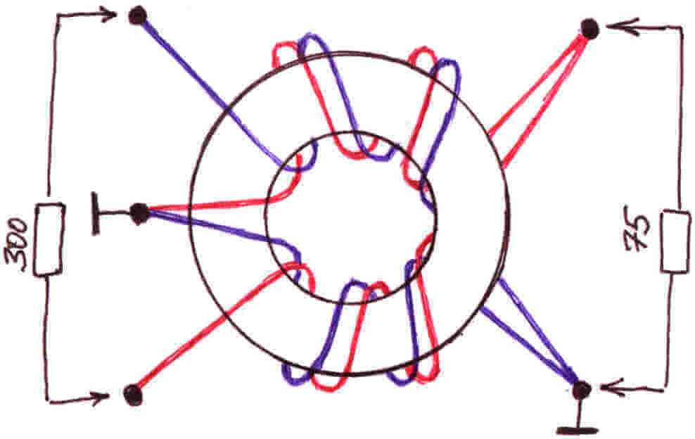
Idea # 3 - Home HDTV Device
If the first 2 options worked at a frequency of no more than 270 MHz, then the next manufacturing method will allow you to enjoy a better picture, because the signal range can reach up to 490 MHz. The only detail that is unlikely to be found among the household trivia is the 300 to 75 ohm matching transformer. You will need to buy it in advance if you decide to make an antenna for your TV yourself as an experiment and improve your skills. Although there are instructions for making a homemade transformer, you can find and use it.

From the materials you will need:
- Scotch
- Cardboard
- Stationery knife
- Foil
- Stapler
- Scissors
- Marker
- Roulette
Having prepared this whole school set, let's get down to business!
First you need to sketch (or print on a computer) this diagram:


Now, according to the scheme, we cut out all the parts, including the necessary pieces of foil:


After that, you need to make a reflector measuring 35 * 32.5 cm (height and width). We glue one of the sides with foil.


In the middle we cut out two identical rectangles, which are necessary in order to completely assemble the homemade antenna signal trap for the TV. The rectangle should be 3.5 cm long, its purpose is to maintain the distance between the reflector and the auxiliary parts.


We glue the parts on a rectangle, and when the cardboard homemade product hardens, we drill holes for the TV cable.


We connect the transformer and insert the cable into the plug. More powerful TV antenna is ready to use! It should also be noted that this homemade option is suitable only for indoor use, because the paper quickly deteriorates on the street.
Another option for a powerful home-made device:
Idea number 4 - Apartment option
There is another way to make a powerful antenna for a TV from improvised means, which is suitable for both street and apartment use.
To manufacture the device, you will need the following materials and tools:
- 4-meter copper wire with a cross section of 4 mm square;
- board of any thickness, 55 cm long and 7 cm wide;
- wood screws;
- ruler or tape measure;
- simple pencil;
- screwdriver;
- soldering iron;
- plug.
So, first, according to the drawing, we drill holes in the board: 
Then we transfer the drawing data to the board and drill into the corresponding attachment points. 
Next, the copper wire must be cut into 8 pieces of 37.5 cm each. 
The insulation must be removed in the middle of each of the 37.5 cm lines (as shown in the picture). 
We cut off 2 more copper wire pieces 22 cm long and conditionally divide them into 3 equal parts, while at the points of inflection, again, we remove the insulation. 
We bend the prepared wire in bare places. We draw your attention to the fact that for those segments that are bent in half, the distance between the ends must be made 7.5 cm (the optimal value for receiving the signal of a homemade television antenna). 
Next, we attach the plug to the finished homemade product, and we already connect the TV cable to it. 
 This completes the manufacturing process. We choose a suitable place and install the device.
Here we have provided the most simple instructions. We hope that now you know how to make a home TV antenna with your own hands! We draw your attention to the fact that today on the Internet you can find many other options in which inventors do without cans and wires. Of the rest of the available tools, copper tubes, aluminum discs and electrodes are often used. The advantage of the options we have listed is that you can quickly make such TV antennas with your own hands, without spending the whole evening on it.
Related materials:
Visual video instructions for creating a simple antenna from cans
Assembling a digital antenna from a TV cable and a cardboard box
HDTV antenna from available tools
Like( 0 ) I do not like( 0 )
Which antenna to choose for digital TV? What is the difference between antennas? How do I apply power to an active antenna? Which antenna is better? These and other questions on the site
Hello everyone! By the nature of my activity, I have to deal very closely with the connection and tuning of antennas for digital terrestrial television.
Therefore, based on the experience gained, I have the opportunity to share how to choose an antenna for digital television and set up dvb-t2 - 20 free channels.
Fast navigation through the article
Which antenna is suitable for digital television DVB-T2
With the advent of digital terrestrial television, many have questions related to the choice of an antenna for DVB-T2. For instance!
- Can I use my old antenna, if there was one?
- Is the "Lattice" type antenna suitable for this?
- Do I need an antenna with or without an amplifier?
- if there is a question about purchasing a new one?
- Do I need an advertised antenna "Key to Free TV"
Let's first figure out what kind of antennas there are.
To receive television signals, antennas of the meter (MV) and decimeter (UHF) ranges are used. There are broadband antennas, this is a "hybrid" when the elements of the MV and UHF bands are used in the antenna design.
These antennas are easy to distinguish from each other by their size.
The MV range has longer elements. Everything is according to the name.
So in MV antennas, the elements are approximately from half a meter to one and a half meters in length.
And the elements of the UHF antenna are only about 15 to 40 cm long.
It is the UHF range antenna that is needed for digital terrestrial television.
 VHF antenna
  An example of an antenna of the decimeter range (UHF)
  Broadband antenna, MV and UHF bands.
  Lattice antenna
  Broadband antenna "Kolibri"
 So - To receive digital terrestrial television, you need an antenna of the decimeter range, i.e. antenna with short elements. Or broadband.
Now you can assess whether your old antenna is suitable for receiving television in the DVB-T2 format. The only open question is its serviceability and efficiency in your area.
In addition to being divided according to the received bands, antennas are also divided into ...
Indoor and outdoor (External) - I think everything is clear with the application here.
And also active and passive - more on that later.
Well, a brief excursion into the difficult topic of terrestrial antennas is carried out. Let's continue ...
Features of the distribution of a television signal
The distance over which the signal is transmitted in the UHF range does not differ in a large coverage area. It is much less than in the meter range.
For example:
If you used a radio receiver, you might have noticed that you cannot catch distant foreign radio stations in the FM or VHF bands, but only those that are nearby are local.
But on the other hand, you can catch a whole bunch of foreign products in the MF or HF bands.
This is because medium and short waves, like meter ones, propagate over long distances, and ultrashort ones, like UHF, to small ones.
This disadvantage of the UHF range for digital TV is compensated by the location and number of television transmitters - by analogy with cell towers, there are many of them.
Also keep in mind that the TV signal is perfectly reflected from the objects encountered on the way.
This allows you to receive transmissions when it is not possible to direct the antenna towards the TV tower. Or there are obstacles to the direct signal flow.
Take a look around! Is it possible to receive the reflected signal?
So with the right antenna selection and proper installation, you will surely succeed.

What else to consider when choosing an antenna
The conditions for receiving a television signal are very different in different places and these conditions must be taken into account when choosing an antenna.
Here are some factors that determine which antenna you need to purchase and how to install it.
- TV transmitter power and
- Terrain relief - mountains, lowlands, plains.
- Standing nearby and blocking the antenna towards the tower, there are tall, dense trees.
- The development of high-rise buildings and your location in relation to these buildings and the tower.
- The floor on which you live - the higher, the easier it is to need an antenna.
- Possibility or inability to rotate the antenna towards the transmitting tower.
Active and passive antennas - what's the difference?
Antennas of any kind can be either active or passive.
Passive antennas are those that amplify the signal only due to their design, without the use of electronic amplifiers, such antennas are used in areas of a confident signal.
Active antenna - it has an amplifier in its design, such an antenna needs to be connected to a power source.
The amplifier helps to raise the received signal level in areas of poor reception.
How to connect power to an active antenna amplifier, several ways
The antenna amplifiers are powered by 12 or 5 volts. But recently, more and more, manufacturers are aiming at the production of antennas with a five-volt power supply.
And there is a reason for this! Such antennas are easier to connect to those who use a DVB-T2 set-top box.
Three ways to connect
A) Use a special power supply unit with a separator that produces a voltage corresponding to your amplifier.
The purpose of the separator is to separate. It passes voltage to the antenna, but does not pass it into the socket of the TV. However, this does not interfere with the signal from the antenna amplifier to the TV.
B) If the DVB-T2 prefix is used. The 5 volt voltage can be supplied directly from the console. Moreover, for any amplifiers for both 5 and 12 volts.
This does not require any additional wire, power supply, and so on. The voltage of 5 volts, from the antenna jack of the set-top box, directly through the antenna cable, will go to the amplifier.
You just need to turn on this power directly from the set-top box menu. Go to the settings section and find the item "Antenna power ON-OFF", select ON, and exit the menu (in different models of prefixes, the names of these items may differ)
C) If you have an LCD TV with a built-in DVB-T2 tuner, then, in addition to the method under the letter A), you can do the following.
You will have to purchase a special adapter for powering the amplifier from any USB port, first of all, the USB port of the LCD TV itself is considered. But you can connect to any charger with USB output

Which antenna to choose - consider examples
As you understood from all of the above, when choosing an antenna for yourself, you need to evaluate various factors.
A few examples:
Distance to the tower 5-15 km
You live in a city where there is a DVB-T2 signal transmitter. Or in a village, not far from the transmitter, 5-15 km.
Most likely, an indoor antenna, even the simplest one, is suitable for you. Especially if you live above the first floor.
And being not far from the tower, even a simple piece of wire instead of an antenna can be enough.
Considering the prevalence of towers and the rather large number of places with a reliable signal, scammers use this, offering various, in fact
Under the conditions described above, they will work pretty well.
But keep in mind that the number of channels will be no more than that broadcast by the TV tower in your area! And not 100 or 200 as the advertisement promises.
Therefore, the question arises, is it necessary to pay off several hundred, or even thousands, for an ordinary indoor antenna from advertising?!
Here are some inexpensive, compact antenna options for good signal conditions.
 Indoor antenna for locations close to the tower.
  Indoor antenna for locations close to the tower. Another option
  This option can work in slightly more difficult conditions than the previous two, especially the version with an amplifier.
 Indoor antenna - application features
The right place for an indoor antenna is not where it will look good or stand comfortably, but where it will receive good signal. And these two circumstances - "look" and "accept" do not always coincide.
Because often the best, and sometimes the only place where you can catch a signal, this is the place at the window of the TV tower overlooking the direction. Take this into account!
To solve this problem, you can add a cable of the required length and for some antennas (for example, those in the photo above) it is not difficult.
But there are indoor antennas that have a built-in power supply in their case. They also have a power cord for plugging into an outlet. And of course a cable for connecting to a TV.

This may sound convenient, but alas, it is not always the case.
Often, the place where the antenna is able to receive a TV signal is not at all near the TV and the outlet, but for example by the window.
And in this case, a short power cord will become an obstacle to positioning the antenna in the right place. In addition to the cable, you also have to pull the extension cord. In general, a bunch of wires.
You live at a distance of about 25-30 km or more from the TV tower.
Of course, a lot depends on the power of the transmitter.
But in general, a small outdoor antenna is sufficient at a distance of 25 km. As for example, those that are shown at the very beginning of this post, I mean the UHF antenna or the broadband "Hummingbird".
In my area, from a distance of 25 km in line of sight, a passive UHF antenna with an arrow length of about 80 cm receives a confident reception without the need to raise the antenna above two meters from the ground.
You can also receive a good active indoor antenna.
In some houses, even from the first floor, if there is a window towards the tower or the ability to receive reflected signals from neighboring buildings.
A floor above the second significantly increases the chance of success.
There is a simple principle of how to determine the antenna power - the longer the antenna boom, the greater the coefficient of its own gain, and not due to the amplifier.
Antenna for difficult reception conditions
For example, the active antenna of the photo below, in our area, pulls out a signal from a distance of 60 km or more. It is successfully used in the most difficult places, in houses located in a strong lowland, its length is about 1.7 meters, but there are antennas under 4 meters in length.
 In addition to the length, in difficult conditions or at a great distance from the TV tower, the presence of an amplifier plays an important role, i.e. the antenna must be active.
There are options for powerful antennas, where instead of one boom, three are used at once, so the antenna's ability to amplify the signal due to the construction alone is greatly increased.
And in tandem with an amplifier, this antenna becomes a very powerful TV signal trap.

But impressed by this antenna, do not rush to run after it. It is only needed under really very, very difficult conditions of admission.
In most cases, other, much cheaper options are sufficient. In addition, if the signal in your area is already strong, then the amplifier in the antenna will only interfere.
Here is just the case when butter porridge can be spoiled. An example of this is described below.
Polish antenna array for digital television
In some cases, the "Lattice" antenna can work quite successfully when receiving digital television. Especially if you are not very close to the transmission tower.
More than once, however, I came across a situation when, using their old antenna - Pole (Lattice), people could not get a digital broadcast signal from it.
Either in general, or the signal periodically "fell off", the picture fell into cubes, the image and sound were frozen. One of the digital TV packages could be missing, while the other worked fine.
The problem with these phenomena is signal over-amplification.
There is a way out, consider the options….
1) Sometimes it's just enough to disconnect the antenna power supply from the outlet and that's it. But this does not always help, and then more serious measures are needed.
2) Reduce the supply voltage of the amplifier using a regulated power supply. Or supply power directly from the set-top box bypassing the separator of the standard antenna power supply by installing a regular plug.
3) Get to the amplifier board, the one on the antenna itself, and connect everything without an amplifier.
4) Throw away this old dilapidated antenna and buy a normal, UHF range.
P.S. New, like a lattice.
I hope this article will be useful to someone, leave your feedback, comments, share your experience.
P.S. If you are purchasing a new antenna and are not sure if it will work for you, ask your local antenna vendor.
It happens that they are quite well aware of which antenna is better to take focusing on your place of residence.
And negotiate the possibility, if it suddenly does not fit, change to an antenna of a different type. At least in my store it is possible.
With support for DVB-T2 and of course he needed an antenna, which naturally needs to be done by hand. How to make an antenna for DVB-T2 with your own hands will be discussed further.
To begin with, I decided to test the Kharchenko biquadrat antenna, or simply the "eight". For manufacturing, we need a copper or aluminum wire with a diameter of 2-5 mm. I had a 2.5 square VVG at hand and I decided to try to make an antenna for DVB-T2 out of it.
Antenna calculation
We find out our frequencies of both DVB-T2 packets in our area. To do this, you can go to the website of the CETV Interactive Map and see which tower is closer to you, one or both channel packages are broadcasting and at what frequencies. In the suburbs of St. Petersburg, these are 586 MHz and 666 MHz.
Now, knowing the packet frequency, we need to calculate the length of the side of the square of our DVB-T2 antenna. It is equal to a quarter of the wavelength.
That is, for our 586 MHz: 300000000/586000000=0,51 meter. Quarter wavelength respectively 0,51/4=0,127 meters or 12,7 cm.
For the second multiplex 666 MHz, we calculate in the same way and get 11,2 cm.
We are interested in L1. H and B for antenna with reflector (grating), amplifies the signal. I did without it.
Now if we make an antenna for two packages of DVB-T2 channels, we determine the average length. That is, we add up our lengths and divide in half.
L1 = (12.7 + 11.2) / 2 = 11.95 round up to 12 cm.
Antenna assembly for DVB-T2
Everything should be clear here. We take our segment of VVG or whatever you have. To determine the approximate length of the wire required for assembling the antenna, you can L1 * 8 and throw a couple of centimeters. 12 * 8 + 2 = 98 cm was needed to make my antenna.
If you have a thick wire 4-5 mm in diameter, then most likely you will not be able to do without a vice. The pliers were enough for me.
We strip the wire from insulation. Then bend the biquadrat with pliers. We look at the pictures. All angles are at 90 degrees.

Then we solder the 75 Ohm TV cable. We solder the vein to one square, Braid to another.

The signal at high frequencies spreads over the surface of the conductor, so it is better to paint the antenna after assembly. I used leftover acrylic facade paint. It is better to fill the place of soldering with hot glue or sealant.
We fasten the wire from the soldering point with ties (straps) along the sides of the square, as in the photo. This mandatory step is antenna matching.
Testing a homemade antenna on a homemade TV
So the biquadrat gives a signal amplification of about 6 dB, and up to the tower 26 km in a straight line. Although the CETV website indicates that we are in the zone of a confident signal, I doubted and prepared it a long time ago.
I went up to the second floor of the house and pulled out the antenna to the scaffolding. He pointed in the direction of the tower and turned on the TV. The TV confidently received both digital TV packages.
I brought the homemade antenna into the house, the TV continued to show confidently and perfectly.


