Multivibrators are another form of oscillators. An oscillator is an electronic circuit that is capable of maintaining an alternating current signal at its output. It can generate square, linear or pulse signals. To oscillate, the generator must satisfy two Barkhausen conditions:
T loop gain should be slightly greater than unity.
The cycle phase shift must be 0 degrees or 360 degrees.
To satisfy both conditions, the oscillator must have some form of amplifier, and part of its output must be regenerated into the input. If the gain of the amplifier is less than one, the circuit will not oscillate, and if it is greater than one, the circuit will be overloaded and produce a distorted waveform. A simple generator can generate a sine wave, but cannot generate a square wave. A square wave can be generated using a multivibrator.
A multivibrator is a form of generator that has two stages, thanks to which we can get a way out of any of the states. These are basically two amplifier circuits arranged with regenerative feedback. In this case, none of the transistors conducts at the same time. Only one transistor is conducting at a time, while the other is in the off state. Some circuits have certain states; the state with fast transition is called switching processes, where there is a rapid change in current and voltage. This switching is called triggering. Therefore, we can run the circuit internally or externally.
Circuits have two states.
One is the steady state, in which the circuit remains forever without any triggering.
The other state is unstable: in this state, the circuit remains for a limited period of time without any external triggering and switches to another state. Hence, the use of multivibartors is done in two state circuits such as timers and flip-flops.
Astable multivibrator using transistor
It is a free-running generator that continuously switches between two unstable states. In the absence of an external signal, the transistors alternately switch from the off state to the saturation state at a frequency determined by the RC time constants of the communication circuits. If these time constants are equal (R and C are equal), then a square wave with a frequency of 1/1.4 RC will be generated. Hence, an astable multivibrator is called a pulse generator or square wave generator. The greater the value of the base load R2 and R3 relative to the collector load R1 and R4, the greater the current gain and the sharper the signal edge will be.
The basic principle of operation of an astable multivibrator is a slight change in the electrical properties or characteristics of the transistor. This difference causes one transistor to turn on faster than the other when power is first applied, causing oscillation.
Diagram Explanation
An astable multivibrator consists of two cross-coupled RC amplifiers.
The circuit has two unstable states
When V1 = LOW and V2 = HIGH then Q1 ON and Q2 OFF
When V1 = HIGH and V2 = LOW, Q1 is OFF. and Q2 ON.
In this case, R1 = R4, R2 = R3, R1 must be greater than R2
C1 = C2
When the circuit is first turned on, none of the transistors are turned on.
The base voltage of both transistors begins to increase. Either transistor turns on first due to the difference in doping and electrical characteristics of the transistor.
Rice. 1: Schematic diagram of the operation of a transistor astable multivibrator
We can't tell which transistor conducts first, so we assume Q1 conducts first and Q2 is off (C2 is fully charged).
Q1 is conducting and Q2 is off, hence VC1 = 0V since all current to ground is due to Q1 short circuit, and VC2 = Vcc since all voltage across VC2 drops due to TR2 open circuit (equal to supply voltage) .
Due to the high voltage of VC2, capacitor C2 starts charging through Q1 through R4 and C1 starts charging through R2 through Q1. The time required to charge C1 (T1 = R2C1) is longer than the time required to charge C2 (T2 = R4C2).
Since the right plate C1 is connected to the base of Q2 and is charging, then this plate has a high potential and when it exceeds the voltage of 0.65V, it turns on Q2.
Since C2 is fully charged, its left plate has a voltage of -Vcc or -5V and is connected to the base of Q1. Therefore it turns off Q2
TR Now TR1 is off and Q2 is conducting, hence VC1 = 5 V and VC2 = 0 V. The left plate of C1 was previously at -0.65 V, which begins to rise to 5 V and connects to the collector of Q1. C1 first discharges from 0 to 0.65V and then begins to charge through R1 through Q2. During charging, the right plate C1 is at low potential, which turns off Q2.
The right plate of C2 is connected to the collector of Q2 and is pre-positioned at +5V. So C2 first discharges from 5V to 0V and then starts charging through resistance R3. The left plate C2 is at high potential during charging, which turns on Q1 when it reaches 0.65V.
Rice. 2: Schematic diagram of the operation of a transistor astable multivibrator
![]()
Now Q1 is conducting and Q2 is off. The above sequence is repeated and we get a signal at both the collectors of the transistor which is out of phase with each other. To obtain a perfect square wave by any collector of the transistor, we take both the collector resistance of the transistor, the base resistance, i.e. (R1 = R4), (R2 = R3), and also the same value of the capacitor, which makes our circuit symmetrical. Therefore, the duty cycle for low and high output is the same that generates a square wave
Constant The time constant of the waveform depends on the base resistance and collector of the transistor. We can calculate its time period by: Time constant = 0.693RC
The principle of operation of a multivibrator on video with explanation
In this video tutorial from the Soldering Iron TV channel, we will show how the elements of an electrical circuit are interconnected and get acquainted with the processes occurring in it. The first circuit on the basis of which the operating principle will be considered is a multivibrator circuit using transistors. The circuit can be in one of two states and periodically transitions from one to another.
Analysis of 2 states of the multivibrator.
All we see now are two LEDs blinking alternately. Why is this happening? Let's consider first first state.
The first transistor VT1 is closed, and the second transistor is completely open and does not interfere with the flow of collector current. The transistor is in saturation mode at this moment, which reduces the voltage drop across it. And therefore the right LED lights up at full strength. Capacitor C1 was discharged at the first moment of time, and the current freely passed to the base of transistor VT2, completely opening it. But after a moment, the capacitor begins to quickly charge with the base current of the second transistor through resistor R1. After it is fully charged (and as you know, a fully charged capacitor does not pass current), the transistor VT2 therefore closes and the LED goes out.
The voltage across capacitor C1 is equal to the product of the base current and the resistance of resistor R2. Let's go back in time. While transistor VT2 was open and the right LED was on, capacitor C2, previously charged in the previous state, begins to slowly discharge through the open transistor VT2 and resistor R3. Until it is discharged, the voltage at the base of VT1 will be negative, which completely turns off the transistor. The first LED is not lit. It turns out that by the time the second LED fades out, capacitor C2 has time to discharge and becomes ready to pass current to the base of the first transistor VT1. By the time the second LED stops lighting, the first LED lights up.
A in the second state the same thing happens, but on the contrary, transistor VT1 is open, VT2 is closed. The transition to another state occurs when capacitor C2 is discharged, the voltage across it decreases. Having completely discharged, it begins to charge in the opposite direction. When the voltage at the base-emitter junction of transistor VT1 reaches a voltage sufficient to open it, approximately 0.7 V, this transistor will begin to open and the first LED will light up.
Let's look at the diagram again.
Through resistors R1 and R4, the capacitors are charged, and through R3 and R2, discharge occurs. Resistors R1 and R4 limit the current of the first and second LEDs. Not only the brightness of the LEDs depends on their resistance. They also determine the charging time of the capacitors. The resistance of R1 and R4 is selected much lower than R2 and R3, so that the charging of the capacitors occurs faster than their discharge. A multivibrator is used to produce rectangular pulses, which are removed from the collector of the transistor. In this case, the load is connected in parallel to one of the collector resistors R1 or R4.
The graph shows the rectangular pulses generated by this circuit. One of the regions is called the pulse front. The front has a slope, and the longer the charging time of the capacitors, the greater this slope will be.

If a multivibrator uses identical transistors, capacitors of the same capacity, and if resistors have symmetrical resistances, then such a multivibrator is called symmetrical. It has the same pulse duration and pause duration. And if there are differences in parameters, then the multivibrator will be asymmetrical. When we connect the multivibrator to a power source, at the first moment of time both capacitors are discharged, which means that current will flow to the base of both capacitors and an unsteady operating mode will appear, in which only one of the transistors should open. Since these circuit elements have some errors in ratings and parameters, one of the transistors will open first and the multivibrator will start.
If you want to simulate this circuit in the Multisim program, then you need to set the values of resistors R2 and R3 so that their resistances differ by at least a tenth of an ohm. Do the same with the capacitance of the capacitors, otherwise the multivibrator may not start. In the practical implementation of this circuit, I recommend supplying voltage from 3 to 10 Volts, and now you will find out the parameters of the elements themselves. Provided that the KT315 transistor is used. Resistors R1 and R4 do not affect the pulse frequency. In our case, they limit the LED current. The resistance of resistors R1 and R4 can be taken from 300 Ohms to 1 kOhm. The resistance of resistors R2 and R3 is from 15 kOhm to 200 kOhm. Capacitor capacity is from 10 to 100 µF. Let's present a table with the values of resistances and capacitances, which shows the approximate expected pulse frequency. That is, to get a pulse lasting 7 seconds, that is, the duration of the glow of one LED is equal to 7 seconds, you need to use resistors R2 and R3 with a resistance of 100 kOhm and a capacitor with a capacity of 100 μF.
Conclusion.
The timing elements of this circuit are resistors R2, R3 and capacitors C1 and C2. The lower their ratings, the more often the transistors will switch, and the more often the LEDs will flicker.
A multivibrator can be implemented not only on transistors, but also on microcircuits. Leave your comments, don’t forget to subscribe to the “Soldering Iron TV” channel on YouTube so you don’t miss new interesting videos.
Another interesting thing about the radio transmitter.
A multivibrator is a device for creating non-sinusoidal oscillations. The output produces a signal of any shape other than a sine wave. The signal frequency in a multivibrator is determined by resistance and capacitance, rather than inductance and capacitance. The multivibrator consists of two amplifier stages, the output of each stage is fed to the input of the other stage.
Multivibrator operating principle
A multivibrator can create almost any waveform, depending on two factors: the resistance and capacitance of each of the two amplifier stages and where the output is taken from in the circuit.
For example, if the resistance and capacitance of two stages are equal, one stage conducts 50% of the time and the other stage conducts 50% of the time. For the discussion of multivibrators in this section, it is assumed that the resistance and capacitance of both stages are equal. When these conditions exist, the output signal is a square wave.
Bistable multivibrators (or “flip-flops”) have two stable states. At steady state, one of the two amplifier stages is conducting and the other stage is not conducting. In order to move from one stable state to another, a bistable multivibrator must receive an external signal.
This external signal is called an external trigger pulse. It initiates the transition of the multivibrator from one state to another. Another trigger pulse is needed to force the circuit back to its original state. These trigger pulses are called "start" and "reset".

Apart from the bistable multivibrator, there are also a monostable multivibrator, which has only one stable state, and an astable multivibrator, which has no stable state.
This lesson will be devoted to a rather important and popular topic: multivibrators and their applications. If I just tried to list where and how self-oscillating symmetrical and asymmetrical multivibrators are used, it would require a decent number of pages of the book. There is, perhaps, no branch of radio engineering, electronics, automation, pulse or computer technology where such generators are not used. This lesson will provide theoretical information about these devices, and at the end, I will give several examples of their practical use in relation to your creativity
Self-oscillating multivibrator
Multivibrators are electronic devices that generate electrical oscillations that are close to rectangular in shape. The spectrum of oscillations generated by a multivibrator contains many harmonics - also electrical oscillations, but multiples of the oscillations of the fundamental frequency, which is reflected in its name: “multi-many”, “vibro-oscillate”.
Let's consider the circuit shown in (Fig. 1,a). Do you recognize? Yes, this is a circuit of a two-stage transistor amplifier 3H with output to headphones. What happens if the output of such an amplifier is connected to its input, as shown by the dashed line in the diagram? A positive feedback arises between them and the amplifier will self-excite and become a generator of audio frequency oscillations, and in telephones we will hear a low-pitched sound. This phenomenon is being vigorously fought in receivers and amplifiers, but for automatically operating devices it turns out to be useful.
Rice. 1 A two-stage amplifier covered by positive feedback becomes a multivibrator
Now look at (Fig. 1, b). On it you see a diagram of the same amplifier covered positive feedback , as in (Fig. 1, a), only its outline is slightly changed. This is exactly how circuits of self-oscillating, i.e., self-exciting multivibrators are usually drawn. Experience is perhaps the best method of understanding the essence of the action of a particular electronic device. You have been convinced of this more than once. And now, in order to better understand the operation of this universal device - an automatic machine, I propose to conduct an experiment with it. You can see the schematic diagram of a self-oscillating multivibrator with all the data on its resistors and capacitors in (Fig. 2, a). Mount it on a breadboard. Transistors must be low-frequency (MP39 - MP42), since high-frequency transistors have a very low breakdown voltage of the emitter junction. Electrolytic capacitors C1 and C2 - type K50 - 6, K50 - 3 or their imported analogues for a rated voltage of 10 - 12 V. The resistor resistances may differ from those indicated in the diagram by up to 50%. It is only important that the values of the load resistors Rl, R4 and the base resistors R2, R3 be as similar as possible. For power use a Krona battery or power supply. Connect a milliammeter (PA) to the collector circuit of any of the transistors for a current of 10 - 15 mA, and connect a high-resistance DC voltmeter (PU) to the emitter-collector section of the same transistor for a voltage of up to 10 V. Having checked the installation and especially carefully the polarity of the electrolytic switching capacitors, connect a power source to the multivibrator. What do the measuring instruments show? Milliammeter - the current of the transistor collector circuit sharply increases to 8 - 10 mA, and then also sharply decreases almost to zero. The voltmeter, on the contrary, either decreases to almost zero or increases to the voltage of the power source, the collector voltage. What do these measurements indicate? The fact that the transistor of this arm of the multivibrator operates in switching mode. The highest collector current and at the same time the lowest voltage on the collector correspond to the open state, and the lowest current and the highest collector voltage correspond to the closed state of the transistor. The transistor of the second arm of the multivibrator works exactly the same way, but, as they say, with 180° phase shift : When one of the transistors is open, the other one is closed. It is easy to verify this by connecting the same milliammeter to the collector circuit of the transistor of the second arm of the multivibrator; the arrows of the measuring instruments will alternately deviate from the zero scale marks. Now, using a clock with a second hand, count how many times per minute the transistors switch from open to closed. About 15 - 20 times. This is the number of electrical oscillations generated by the multivibrator per minute. Therefore, the period of one oscillation is 3 - 4 s. While continuing to monitor the milliammeter needle, try to depict these fluctuations graphically. On the horizontal ordinate axis, plot, on a certain scale, the time intervals when the transistor is in the open and closed states, and on the vertical axis, plot the collector current corresponding to these states. You will get approximately the same graph as the one shown in Fig. 2, b.
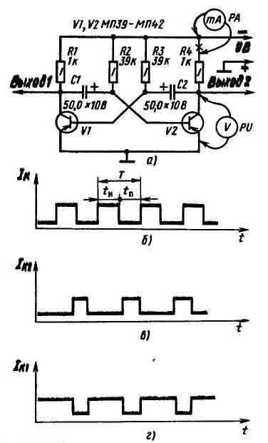
Rice. 2 Diagram of a symmetrical multivibrator (a) and the current pulses generated by it (b, c, d).
This means that we can assume that The multivibrator generates rectangular electrical oscillations. In the multivibrator signal, regardless of which output it is taken from, it is possible to distinguish current pulses and pauses between them. The time interval from the moment of the appearance of one current (or voltage) pulse until the moment of the appearance of the next pulse of the same polarity is usually called the pulse repetition period T, and the time between pulses with a pause duration Tn - Multivibrators that generate pulses whose duration Tn is equal to the pauses between them are called symmetrical . Therefore, the experienced multivibrator you assembled is symmetric. Replace capacitors C1 and C2 with other capacitors with a capacity of 10 - 15 µF. The multivibrator remained symmetrical, but the frequency of the oscillations it generated increased by 3 - 4 times - to 60 - 80 per minute or, what is the same, to approximately 1 Hz. The arrows of measuring instruments barely have time to follow changes in currents and voltages in transistor circuits. And if capacitors C1 and C2 are replaced with paper capacitances of 0.01 - 0.05 μF? How will the arrows of measuring instruments behave now? Having deviated from the zero marks of the scales, they stand still. Maybe generation was disrupted? No! It’s just that the oscillation frequency of the multivibrator has increased to several hundred hertz. These are vibrations in the audio frequency range that DC devices can no longer detect. They can be detected using a frequency meter or headphones connected through a capacitor with a capacity of 0.01 - 0.05 μF to any of the multivibrator outputs or by connecting them directly to the collector circuit of any of the transistors instead of a load resistor. You will hear a low pitch sound on phones. What is the operating principle of a multivibrator? Let's return to the diagram in Fig. 2, a. At the moment the power is turned on, the transistors of both arms of the multivibrator open, since negative bias voltages are applied to their bases through the corresponding resistors R2 and R3. At the same time, the coupling capacitors begin to charge: C1 - through the emitter junction of transistor V2 and resistor R1; C2 - through the emitter junction of transistor V1 and resistor R4. These capacitor charging circuits, being voltage dividers of the power source, create increasingly negative voltages at the bases of the transistors (relative to the emitters), tending to open the transistors more and more. Turning on a transistor causes the negative voltage at its collector to decrease, which causes the negative voltage at the base of the other transistor to decrease, turning it off. This process occurs in both transistors at once, but only one of them closes, on the basis of which there is a higher positive voltage, for example, due to the difference in current transfer coefficients h21e ratings of resistors and capacitors. The second transistor remains open. But these states of transistors are unstable, because electrical processes in their circuits continue. Let's assume that some time after turning on the power, transistor V2 turned out to be closed, and transistor V1 turned out to be open. From this moment, capacitor C1 begins to discharge through the open transistor V1, the resistance of the emitter-collector section of which is low at this time, and resistor R2. As capacitor C1 discharges, the positive voltage at the base of the closed transistor V2 decreases. As soon as the capacitor is completely discharged and the voltage at the base of transistor V2 becomes close to zero, a current appears in the collector circuit of this now opening transistor, which acts through capacitor C2 on the base of transistor V1 and lowers the negative voltage on it. As a result, the current flowing through transistor V1 begins to decrease, and through transistor V2, on the contrary, increases. This causes transistor V1 to turn off and transistor V2 to open. Now capacitor C2 will begin to discharge, but through the open transistor V2 and resistor R3, which ultimately leads to the opening of the first and closing of the second transistors, etc. The transistors interact all the time, causing the multivibrator to generate electrical oscillations. The oscillation frequency of the multivibrator depends both on the capacitance of the coupling capacitors, which you have already checked, and on the resistance of the base resistors, which you can verify now. Try, for example, replacing the basic resistors R2 and R3 with resistors of high resistance. The oscillation frequency of the multivibrator will decrease. Conversely, if their resistance is lower, the oscillation frequency will increase. Another experiment: disconnect the upper (according to the diagram) terminals of resistors R2 and R3 from the negative conductor of the power source, connect them together, and between them and the negative conductor, turn on a variable resistor with a resistance of 30 - 50 kOhm as a rheostat. By turning the axis of the variable resistor, you can change the oscillation frequency of the multivibrators within a fairly wide range. The approximate oscillation frequency of a symmetrical multivibrator can be calculated using the following simplified formula: F = 700/(RC), where f is the frequency in hertz, R is the resistance of the base resistors in kilo-ohms, C is the capacitance of the coupling capacitors in microfarads. Using this simplified formula, calculate which frequency oscillations your multivibrator generated. Let's return to the initial data of resistors and capacitors of the experimental multivibrator (according to the diagram in Fig. 2, a). Replace capacitor C2 with a capacitor with a capacity of 2 - 3 μF, connect a milliammeter to the collector circuit of transistor V2, follow its arrow, and graphically depict the current fluctuations generated by the multivibrator. Now the current in the collector circuit of transistor V2 will appear in shorter pulses than before (Fig. 2, c). The duration of the Th pulses will be approximately the same number of times less than the pauses between Th pulses as the capacitance of capacitor C2 has decreased compared to its previous capacity. Now connect the same (or similar) milliammeter to the collector circuit of transistor V1. What does the measuring device show? Also current pulses, but their duration is much longer than the pauses between them (Fig. 2, d). What happened? By reducing the capacitance of capacitor C2, you have broken the symmetry of the arms of the multivibrator - it has become asymmetrical . Therefore, the vibrations generated by it became asymmetrical : in the collector circuit of transistor V1, the current appears in relatively long pulses, in the collector circuit of transistor V2 - in short ones. Short voltage pulses can be removed from Output 1 of such a multivibrator, and long voltage pulses can be removed from Output 2. Temporarily swap capacitors C1 and C2. Now short voltage pulses will be at Output 1, and long ones at Output 2. Count (on a clock with a second hand) how many electrical pulses per minute this version of the multivibrator generates. About 80. Increase the capacity of capacitor C1 by connecting a second electrolytic capacitor with a capacity of 20 - 30 μF in parallel to it. The pulse repetition rate will decrease. What if, on the contrary, the capacitance of this capacitor is reduced? The pulse repetition rate should increase. There is, however, another way to regulate the pulse repetition rate - by changing the resistance of resistor R2: with a decrease in the resistance of this resistor (but not less than 3 - 5 kOhm, otherwise transistor V2 will be open all the time and the self-oscillating process will be disrupted), the pulse repetition frequency should increase, and with an increase in its resistance, on the contrary, it decreases. Check it out empirically - is this true? Select a resistor of such a value that the number of pulses per minute is exactly 60. The milliammeter needle will oscillate at a frequency of 1 Hz. The multivibrator in this case will become like an electronic clock mechanism that counts the seconds.
Waiting multivibrator
Such a multivibrator generates current (or voltage) pulses when triggering signals are applied to its input from another source, for example, from a self-oscillating multivibrator. To turn the self-oscillating multivibrator, which you have already carried out experiments with in this lesson (according to the diagram in Fig. 2a), into a waiting multivibrator, you need to do the following: remove capacitor C2, and instead connect a resistor between the collector of transistor V2 and the base of transistor V1 (in Fig. 3 - R3) with a resistance of 10 - 15 kOhm; between the base of transistor V1 and the grounded conductor, connect a series-connected element 332 (G1 or other constant voltage source) and a resistor with a resistance of 4.7 - 5.1 kOhm (R5), but so that the positive pole of the element is connected to the base (via R5); Connect a capacitor (in Fig. 3 - C2) with a capacity of 1 - 5 thousand pF to the base circuit of transistor V1, the second output of which will act as a contact for the input control signal. The initial state of transistor V1 of such a multivibrator is closed, transistor V2 is open. Check - is this true? The voltage on the collector of the closed transistor should be close to the voltage of the power source, and on the collector of the open transistor should not exceed 0.2 - 0.3 V. Then turn on a milliammeter to the collector circuit of transistor V1 for a current of 10 - 15 mA and, observing its arrow , connect between the Uin contact and the grounded conductor, literally for a moment, one or two 332 elements connected in series (in the GB1 diagram) or a 3336L battery. Just don’t confuse it: the negative pole of this external electrical signal must be connected to the Uin contact. In this case, the milliammeter needle should immediately deviate to the value of the highest current in the transistor’s collector circuit, freeze for a while, and then return to its original position to wait for the next signal. Repeat this experiment several times. With each signal, the milliammeter will show the collector current of transistor V1 instantly increasing to 8 - 10 mA and after some time also instantly decreasing to almost zero. These are single current pulses generated by a multivibrator. And if you keep the GB1 battery connected to the Uin terminal for a longer time. The same thing will happen as in previous experiments - only one pulse will appear at the output of the multivibrator. Try it!

Rice. 3 Experienced waiting multivibrator.
And one more experiment: touch the base terminal of transistor V1 with some metal object taken in your hand. Perhaps in this case, the waiting multivibrator will work - from the electrostatic charge of your body. Repeat the same experiments, but connecting the milliammeter to the collector circuit of transistor V2. When a control signal is applied, the collector current of this transistor should sharply decrease to almost zero, and then just as sharply increase to the value of the open transistor current. This is also a current pulse, but of negative polarity. What is the principle of operation of a waiting multivibrator? In such a multivibrator, the connection between the collector of transistor V2 and the base of transistor V1 is not capacitive, as in a self-oscillating one, but resistive - through resistor R3. A negative bias voltage that opens it is supplied to the base of transistor V2 through resistor R2. Transistor V1 is reliably closed by the positive voltage of element G1 at its base. This state of transistors is very stable. They can remain in this state for any amount of time. But at the base of transistor V1 a voltage pulse of negative polarity appeared. From this moment on, the transistors go into an unstable state. Under the influence of the input signal, transistor V1 opens, and the changing voltage on its collector through capacitor C1 closes transistor V2. The transistors remain in this state until capacitor C1 is discharged (through resistor R2 and open transistor V1, the resistance of which is low at this time). As soon as the capacitor is discharged, transistor V2 will immediately open, and transistor V1 will close. From this moment on, the multivibrator is again in its original, stable standby mode. Thus, a waiting multivibrator has one stable and one unstable state . During an unstable state it generates one square pulse current (voltage), the duration of which depends on the capacitance of capacitor C1. The larger the capacitance of this capacitor, the longer the pulse duration. So, for example, with a capacitor capacity of 50 µF, the multivibrator generates a current pulse lasting about 1.5 s, and with a capacitor with a capacity of 150 µF - three times more. Through additional capacitors, positive voltage pulses can be removed from output 1, and negative ones from output 2. Is it only with a negative voltage pulse applied to the base of transistor V1 that the multivibrator can be brought out of standby mode? No, not only. This can also be done by applying a voltage pulse of positive polarity, but to the base of transistor V2. So, all you have to do is experimentally check how the capacitance of capacitor C1 affects the duration of the pulses and the ability to control the standby multivibrator with positive voltage pulses. How can you practically use a standby multivibrator? Differently. For example, to convert sinusoidal voltage into rectangular voltage (or current) pulses of the same frequency, or to turn on another device for some time by applying a short-term electrical signal to the input of a waiting multivibrator. How else? Think!
Multivibrator in generators and electronic switches
Electronic call. A multivibrator can be used for an apartment bell, replacing a regular electric one. It can be assembled according to the diagram shown in (Fig. 4). Transistors V1 and V2 operate in a symmetrical multivibrator, generating oscillations with a frequency of about 1000 Hz, and transistor V3 operates in a power amplifier for these oscillations. The amplified vibrations are converted by the dynamic head B1 into sound vibrations. If you use a subscriber loudspeaker to make a call, connecting the primary winding of its transition transformer to the collector circuit of transistor V3, its case will house all the bell electronics mounted on the board. The battery will also be located there.

Rice. 4. Electronic call based on a multivibrator.
An electronic bell can be installed in the corridor and connected with two wires to the S1 button. When you press the button, sound will appear in the dynamic head. Since power is supplied to the device only during ringing signals, two 3336L batteries connected in series or "Krona" will last for several months of ring operation. Set the desired sound tone by replacing capacitors C1 and C2 with capacitors of other capacities. A multivibrator assembled according to the same circuit can be used to study and train in listening to the telegraph alphabet - Morse code. In this case, you only need to replace the button with a telegraph key.
Electronic switch. This device, the diagram of which is shown in (Fig. 5), can be used to switch two Christmas tree garlands powered by an alternating current network. The electronic switch itself can be powered from two 3336L batteries connected in series, or from a rectifier that would provide a constant voltage of 9 - 12 V at the output.

Rice. 5. Electronic switch based on a multivibrator.
The switch circuit is very similar to the electronic bell circuit. But the capacitances of capacitors C1 and C2 of the switch are many times greater than the capacitances of similar bell capacitors. The switch multivibrator, in which transistors V1 and V2 operate, generates oscillations with a frequency of about 0.4 Hz, and the load of its power amplifier (transistor V3) is the winding of the electromagnetic relay K1. The relay has one pair of contact plates that operate for switching. Suitable, for example, is a RES-10 relay (passport RS4.524.302) or another electromagnetic relay that reliably operates from a voltage of 6 - 8 V at a current of 20 - 50 mA. When the power is turned on, transistors V1 and V2 of the multivibrator alternately open and close, generating square wave signals. When transistor V2 is turned on, a negative supply voltage is applied through resistor R4 and this transistor to the base of transistor V3, driving it into saturation. In this case, the resistance of the emitter-collector section of transistor V3 decreases to several ohms and almost the entire voltage of the power source is applied to the winding of relay K1 - the relay is triggered and its contacts connect one of the garlands to the network. When transistor V2 is closed, the power supply circuit to the base of transistor V3 is broken, and it is also closed; no current flows through the relay winding. At this time, the relay releases the anchor and its contacts, switching, connect the second Christmas tree garland to the network. If you want to change the switching time of the garlands, then replace capacitors C1 and C2 with capacitors of other capacities. Leave the data for resistors R2 and R3 the same, otherwise the DC operation mode of the transistors will be disrupted. A power amplifier similar to the amplifier on transistor V3 can also be included in the emitter circuit of transistor V1 of the multivibrator. In this case, electromagnetic relays (including homemade ones) may not have switching groups of contacts, but normally open or normally closed. The relay contacts of one of the arms of the multivibrator will periodically close and open the power circuit of one garland, and the relay contacts of the other arm of the multivibrator will periodically open the power circuit of the second garland. The electronic switch can be mounted on a board made of getinax or other insulating material and, together with the battery, placed in a plywood box. During operation, the switch consumes a current of no more than 30 mA, so the energy of two 3336L or Krona batteries is quite enough for the entire New Year holidays. A similar switch can be used for other purposes. For example, for illuminating masks and attractions. Imagine a figurine of the hero of the fairy tale “Puss in Boots” cut out of plywood and painted. Behind the transparent eyes there are light bulbs from a flashlight, switched by an electronic switch, and on the figure itself there is a button. As soon as you press the button, the cat will immediately start winking at you. Isn't it possible to use a switch to electrify some models, such as the lighthouse model? In this case, in the collector circuit of the power amplifier transistor, instead of an electromagnetic relay, you can include a small-sized incandescent light bulb, designed for a small filament current, which will imitate the flashes of a beacon. If such a switch is supplemented with a toggle switch, with the help of which two such bulbs can be switched on alternately in the collector circuit of the output transistor, then it can become a direction indicator for your bicycle.
Metronome- this is a kind of clock that allows you to count equal periods of time using sound signals with an accuracy of fractions of a second. Such devices are used, for example, to develop a sense of tact when teaching musical literacy, during the first training in transmitting signals using the telegraph alphabet. You can see a diagram of one of these devices in (Fig. 6).

Rice. 6. Metronome based on a multivibrator.
This is also a multivibrator, but asymmetrical. This multivibrator uses transistors of different structures: Vl - n - p - n (MP35 - MP38), V2 - p - n - p (MP39 - MP42). This made it possible to reduce the total number of parts of the multivibrator. The principle of its operation remains the same - generation occurs due to positive feedback between the output and input of a two-stage 3CH amplifier; communication is carried out by electrolytic capacitor C1. The load of the multivibrator is a small-sized dynamic head B1 with a voice coil with a resistance of 4 - 10 Ohms, for example 0.1GD - 6, 1GD - 8 (or a telephone capsule), which creates sounds similar to clicks during short-term current pulses. The pulse repetition rate can be adjusted by variable resistor R1 from approximately 20 to 300 pulses per minute. Resistor R2 limits the base current of the first transistor when the slider of resistor R1 is in the lowest (according to the circuit) position, corresponding to the highest frequency of generated oscillations. The metronome can be powered by one 3336L battery or three 332 cells connected in series. The current it consumes from the battery does not exceed 10 mA. Variable resistor R1 must have a scale calibrated according to a mechanical metronome. Using it, by simply turning the resistor knob, you can set the desired frequency of the metronome sound signals.
Practical work
For practical work, I advise you to assemble the multivibrator circuits presented in the lesson pictures, which will help you understand the principle of operation of the multivibrator. Next, I propose to assemble a very interesting and useful “Electronic Nightingale Simulator” based on multivibrators, which can be used as a doorbell. The circuit is very simple, reliable, and works immediately if there are no errors in installation and the use of serviceable radio elements. I have been using it as a doorbell for 18 years, to this day. It’s not hard to guess that I collected it when, like you, I was a beginner radio amateur.
Electronic call based on multivibrators
Waiting multivibrators after the arrival of a short trigger pulse, one output pulse is generated. They belong to the class monostable devices and have one long-term stable and one quasi-stable equilibrium state. The circuit of the simplest standby multivibrator based on bipolar transistors, having one resistive and one capacitive collector-base connections, is shown in Fig. 8. Thanks to the base connection VT 2 with power supply + E through R b2, an unlocking current flows in the base circuit, sufficient to saturate this transistor. In this case, the output voltage removed from the collector VT 2 is close to zero. Transistor VT 1 is locked by the negative voltage obtained by dividing the voltage of the bias source - E cm divider R b1 R With. Thus, after turning on the power supplies, the state of the circuit is determined. In this state the capacitor WITH 1 charged to source voltage + E(plus on the left, minus on the right cover).
Rice. 8. Waiting transistor multivibrator
The waiting multivibrator can remain in this state for as long as desired - until the triggering pulse arrives. A positive trigger pulse (Fig. 9) unlocks the transistor VT 1, which leads to an increase in the collector current and a decrease in the collector potential of this transistor. Negative potential gain across a capacitor WITH 1 is transmitted to the base VT 2, brings this transistor out of saturation and causes it to go into active mode. The collector current of the transistor decreases, the voltage at the collector receives a positive increment, which from the collector VT 2 via resistor R c is transmitted to the base VT 1, causing it to further unlock. To reduce unlocking time VT 1 in parallel R c include the accelerating capacitor WITH usk. The process of switching transistors occurs like an avalanche and ends with the transition of the multivibrator to the second quasi-stable equilibrium state. In this state, the capacitor discharges WITH 1 via resistor R b2 and saturated transistor VT 1 per power supply +E. Positively charged plate WITH 1 via saturated transistor VT 1 is connected to the common wire, and the negatively charged one is connected to the base VT 2. Thanks to this, the transistor VT 2 is kept locked. After discharge WITH 1 base potential VT 2 becomes non-negative. This leads to an avalanche-like switching of transistors ( VT 2 is unlocked and VT 1 is locked). The formation of the output pulse ends. Thus, the duration of the output pulse is determined by the process of discharging the capacitor WITH 1
 .
.
Output pulse amplitude
 .
.
At the end of the output pulse formation, the recovery stage begins, during which the capacitor is charged WITH 1 from source + E through a resistor R k1 and the emitter junction of the saturated transistor VT 2. Recovery time
 .
.
The minimum repetition period with which trigger pulses can follow is
 .
.


Rice. 9. Voltage timing diagrams in the waiting multivibrator circuit
Operational amplifiers
Operational amplifiers(OA) are high-quality direct current amplifiers (DCA), designed to perform various operations on analog signals when operating in a circuit with negative feedback.
DC amplifiers allow you to amplify slowly changing signals, since they have a zero lower limiting frequency of the amplification band (f n = 0). Accordingly, such amplifiers do not have reactive components (capacitors, transformers) that do not transmit the DC component of the signal.
In Fig. 10a shows the symbol of the op-amp. The amplifier shown has one output terminal (shown on the right) and two input terminals (shown on the left side). The sign Δ or > characterizes the gain. An input whose voltage is shifted in phase by 180 0 relative to the output voltage is called inverting and is indicated by the inversion sign ○, and the input, the voltage at which is in phase with the output, is non-inverting. The op-amp amplifies the differential (difference) voltage between the inputs. The operational amplifier also contains pins for supplying the supply voltage and may contain frequency correction (FC) pins and balancing pins (NC). To facilitate understanding of the purpose of the outputs and increase the information content in the symbol, it is allowed to introduce one or two additional fields on both sides of the main field, in which labels characterizing the output functions are indicated (Fig. 10, b). Currently, operational amplifiers are produced in the form of integrated circuits. This allows us to consider them as separate components with certain parameters.
The parameters and characteristics of an op-amp can be divided into input, output and transmission characteristics.
Input parameters.


Rice. 10. Symbol of operational amplifier: a – without additional field; b – with an additional field; NC – balancing terminals; FC – frequency correction outputs; U – supply voltage terminals; 0V – common output
Transmission characteristics.
Voltage Gain TO U (10 3 – 10 6)
 ,
,
Where U input1 , U vx2– voltage at the inputs of the op-amp.
Common Mode Ratio TO U sf
 .
.
Common mode rejection ratio TO os sf
 .
.
The unity gain frequency f 1 is the frequency at which the voltage gain is equal to unity (units are tens of MHz).
The rate of rise of the output voltage V U out is the maximum possible rate of change of the output signal.
Output parameters.
Maximum output voltage of the op amp U out max. Typically, this voltage is 2-3 V lower than the power supply voltage.
Output resistance Rout (tens - hundreds of Ohms).
Basic circuits for connecting an operational amplifier.
Op amps are typically used with deep negative feedback because they have significant voltage gain. In this case, the resulting parameters of the amplifier depend on the elements of the feedback circuit.
Depending on which input of the op-amp the input signal source is connected to, there are two main connection schemes (Fig. 11). When the input voltage is applied to the non-inverting input (Fig. 11, a), the voltage gain is determined by the expression
 . (1)
. (1)
This inclusion of an op-amp is used when increased input impedance is required. If in the diagram Fig. 11, and remove resistance R 1 and short-circuit resistance R 2, you get a voltage follower ( TO u=1), which is used to match the high impedance of the signal source and the low impedance of the receiver.


Rice. 11. Op-amp amplifier circuits: a – non-inverting amplifier; b – inverting amplifier
When the input voltage is applied to the inverting input (Fig. 11, b), the gain is equal to
 . (2)
. (2)
As can be seen from expression (2), with this connection, the input voltage is inverted.
In the considered circuits, a resistance R e is connected to one of the inputs. It does not affect gain and is introduced when necessary to reduce output voltage variations caused by temporary or temperature variations in input currents. Resistance R e is chosen such that the equivalent resistances connected to the op-amp inputs are the same. For the diagrams in Fig. 10  .
.
By modifying the diagram in Fig. 11, b, you can get a summing device (Fig. 12, a), in which
 . (3)
. (3)
When voltage is simultaneously applied to both inputs of the op-amp, a subtractive device is obtained (Fig. 12, b), for which
 . (4)
. (4)
This expression is valid if the condition is met  .
.


Rice. 12. Op-amp switching circuits: a – voltage adder; b – subtracting device
Radio circuits for beginner radio amateurs
In this article we present several devices based on one circuit - an asymmetrical multivibrator using transistors of different conductivities.
flasher
Using this circuit, you can assemble a device with a blinking light bulb (see Fig. 1) and use it for various purposes. For example, install it on a bicycle to power turn lights, or in a lighthouse model, a signal light, or on a car or ship model as a flashing light.
The load of an asymmetrical multivibrator assembled on transistors T1, T2 is light bulb L1. The pulse repetition rate is determined by the capacitance value of capacitor C1 and resistors R1, R2. Resistor R1 limits the maximum flash frequency, and resistor R2 can be used to smoothly change their frequency. You need to start working from the maximum frequency, which corresponds to the top position of the resistor R2 slider in the diagram.
Please note that the device is powered by a 3336L battery, which produces 3.5 V under load, and the L1 light bulb is used at a voltage of only 2.5 V. Will it burn out? No! The duration of its glow is very short, and the thread does not have time to overheat. If the transistors have a high gain, then instead of a 2.5 V x 0.068 A light bulb, you can use a 3.5 V x 0.16 A light bulb. Transistors like MP35-MP38 are suitable for transistor T1, and transistors like MP39-MP42 are suitable for T2.
Metronome
If you install a loudspeaker in the same circuit instead of a light bulb, you will get another device - an electronic metronome. It is used in teaching music, for keeping time during physical experiments, and in photographic printing.
If you slightly change the circuit - reduce the capacitance of capacitor C1 and introduce resistor R3, then the pulse duration of the generator will increase. The sound will increase (Fig. 2). This device can serve as a house bell, a model horn, or a children's pedal car. (In the latter case, the voltage must be increased to 9 V.) And it can also be used for teaching Morse code. Only then, instead of the Kn1 button, you need to install a telegraph key. The sound tone is selected by capacitor C1 and resistor R2. The larger R3, the louder the sound of the generator. However, if its value is more than one kilo-ohm, then oscillations in the generator may not occur.

The generator uses the same transistors as in the previous circuit, and headphones or a head with a coil resistance of 5 to 65 Ohms are used as a loudspeaker.
Humidity indicator
An asymmetrical multivibrator using transistors of different conductivities has an interesting property: during operation, both transistors are either open or locked at the same time. The current consumed by the switched-off transistors is very small. This makes it possible to create cost-effective indicators of changes in non-electrical quantities, such as humidity indicators. The schematic diagram of such an indicator is shown in Figure 3. As can be seen from the diagram, the generator is constantly connected to the power source, but does not work, since both transistors are locked. Reduces current consumption and resistor R4. A humidity sensor is connected to sockets G1, G2 - two thin tinned wires 1.5 cm long. They are sewn to the fabric at a distance of 3-5 mm from each other. The resistance of the dry sensor is high. When wet it falls. The transistors open, the generator starts working. To reduce the volume, you need to reduce the supply voltage or the value of resistor R3. This humidity indicator can be used when caring for newborn babies.

Humidity indicator with sound and light signal
If you expand the circuit a little, the humidity indicator will emit light simultaneously with the sound signal - light bulb L1 will start to light up. In this case, as can be seen from the diagram (Fig. 4), two asymmetrical multivibrators on transistors of different conductivities are installed in the generator. One is assembled on transistors T1, T2 and is controlled by a humidity sensor connected to sockets G1, G2. The load of this multivibrator is lamp L1. The voltage from the collector T2 controls the operation of the second multivibrator, assembled on transistors T3, T4. It works as an audio frequency generator, and loudspeaker Gr1 is turned on at its output. If there is no need to give a sound signal, then the second multivibrator can be turned off.

The transistors, lamp and loudspeaker used in this humidity indicator are the same as in previous devices.
Siren simulator
Interesting devices can be built using the dependence of the frequency of an asymmetrical multivibrator on transistors of different conductivity on the base current of transistor T1. For example, a generator that simulates the sound of a siren. Such a device can be installed on a model of an ambulance, fire truck, or rescue boat.
The schematic diagram of the device is shown in Figure 5. In the initial position, the Kn1 button is open. Transistors are locked. The generator is not working. When the button is closed, capacitor C2 is charged through resistor R4. The transistors open and the multivibrator starts working. As capacitor C2 charges, the base current of transistor T1 increases and the frequency of the multivibrator increases. When the button is opened, everything repeats in the reverse order. The siren sound is simulated by periodically closing and opening the button. The rate of rise and fall of sound is selected by resistor R4 and capacitor C2. The siren tone is set by resistor R3, and the sound volume by selecting resistor R5. The transistors and loudspeaker are selected the same as in previous devices.

Transistor tester
Considering that this multivibrator uses transistors of different conductivities, you can use it as a device for testing transistors by replacement. The schematic diagram of such a device is shown in Figure 6. The circuit of a sound generator is taken as a basis, but a light pulse generator can be used with equal success.

Initially, by closing the Kn1 button, check the operation of the device. Depending on the type of conductivity, connect the transistor under test to sockets G1 - G3 or G4-G6. In this case, use switch P1 or P2. If there is sound in the loudspeaker when you press the button, then the transistor is working.
As switches P1 and P2, you can take toggle switches with two switching contacts. The figure shows the switches in the "Control" position. The device is powered by a 3336L battery.
Sound generator for testing amplifiers
Based on the same multivibrator, you can build a fairly simple generator for testing receivers and amplifiers. Its circuit diagram is shown in Figure 7. Its difference from a sound generator is that instead of a loudspeaker, a 7-step voltage level regulator is switched on at the output of the multivibrator.

E. TARASOV
Rice Y. CHESNOKOBA
YUT For skillful hands 1979 No. 8