We will not once again recall the proverb that “everything is new”, but simply try to logically judge what 3D graphics accelerators will come to in the near and (even) more or less distant time. We will not argue simply, but in parts. So.
External interfaces and image output
There is no doubt that after some time all display systems (monitors, projectors, etc.) will be connected to the accelerator via a digital interface. In the beginning, these will be the fruits of the evolution of the dedicated interface (DVI), but later, it is quite logical to expect the gradual replacement of the specialized digital serial bus with its general-purpose analog, for example, one of the descendants of USB or FireWire. Why am I sure of this?
Firstly, the resolution and even more so the frame rate of display devices will not grow as rapidly as the computing power of the accelerator. There are several reasons for this, the first of them is the limited resolution of the eye, for which an image with 3..4 thousand horizontal dots is already perceived (if viewed as a whole) as monolithic and infinitely detailed. Secondly, a frame rate above 150..200 image changes per second does not make sense even if there is no smoothing of moving objects: almost a tenfold superiority over the cinematic frequency will provide smoothing of motion due to the inertia of perception in the eye, which will involuntarily accumulate and average over several shots in a row. Of course, options are possible - such as panoramic and spherical displays, or stereo displays that require two pictures for different eyes, but all of them, one way or another, can be content with a resolution of about ten thousand horizontal dots. A further increase in resolution is possible, but does not seem to be a priority - much more effort (already now) is spent on increasing the realism of the picture than on smoothing it.
So, the slow (relatively) increase in resolution and frame rate will soon allow conventional general-purpose buses to serve as a channel for transmitting information to a monitor and other display devices. Why is it important? Because it's very convenient. Imagine that in each of the 6 USB ports you can connect (if desired, by display). Imagine that the most elementary camera or PDA can, if desired, be connected to a projector or monitor through the same interface through which you synchronize and transfer data to a PC. Etc. etc.
In a more distant time, the ability to connect "everything-to-everything" using the same interfaces (+ open data transfer protocols of different formats) will open up excellent prospects, and not only in the field of displaying visual information ...
So, our accelerator of the future has the first more or less distinct element - one or several universal external ports based on high-speed serial buses. By the way, it is not necessarily located on the board (module, card) of the accelerator itself, it can also use motherboard ports for image transfer - all the more so since the system bus will certainly outperform external universal peripheral interfaces in terms of bandwidth.
In the same vein, it is logical to expect the appearance of displays and projectors with built-in radio interfaces (the first models of projectors with 802.11 varieties already exist). It is obvious that all future PCs, PDAs, laptops and other devices will include one or another wireless interface and transferring images to the nearest screen without any wired connection is very convenient, both in business and in domestic or personal applications. Speaking of displays:
Displays and other display systems
Let's discuss the issue of demonstrating images transmitted from the accelerator. First, it is clear that in the near future almost all displays will become flat and use some form of flat panel technology. While we are not talking about projectors, but most of them in our time do not use scanning vacuum tubes, but miniature high-temperature LCD matrices or matrices with arrays of micromechanical mirrors operating through transmission. The resolution and size of displays will grow, but nothing particularly new can be expected here - too large panels are not convenient and even harmful - they take up a lot of space and are not easy to transport (weight, fragility). Therefore, sizes over 20 inches diagonally will still only be reserved for specific niches. The ideal solution for large sizes are certain types of projectors - paired with very compact screens, they can provide an image of different sizes within a fairly wide range, and at the same time they are quite compact devices in themselves.
So, the personal display of the future is a flat panel ranging in size from 17 to 20..24 inches with a resolution of about 3..4 thousand horizontal dots and the maximum physical refresh rate of about 100 frames per second. Next, various projectors and composite panels come into play. The former will receive a higher resolution and brightness, again up to 3..4 thousand dots - which will not only allow you to fully display very high quality films on them, but will also require new standards for shooting, compressing and transmitting a moving image - even advanced HDTV standards are far from such numbers. It is in this area that the most significant progress will occur, in terms of the quality of capturing, storing and transmitting images. But we must not forget that the main topic of this article is 3D graphics in the future.
Secondly, panels capable of creating a three-dimensional image without the use of additional tools, such as special stereo glasses, will become very widespread, if not ubiquitous. This is where different technologies come into play. In the distant future, holographic LCD matrices are likely (I personally know former fellow students engaged in such research for LG), capable of reproducing more characteristics of the captured light stream than traditional systems and giving a three-dimensional, color (!) holographic image. Such solutions will require significantly higher matrix resolution and a special form of data presentation, and therefore they should not be expected to appear in commercial quantities in the next five years. Some hybrid solutions are also possible, in which dynamically adjustable diffractive structures separate the light from the matrix for the right and left eyes, while monitoring the position of the head and providing the optimal depth of the zone of stable perception of the stereo image. And, finally, the most likely systems in the near future with a simple separation of the image for the right and left eyes, based on a single LCD panel. Such systems are already commercially available. It is obvious that in the near future there will be reconfigurable matrices capable of operating both in the mode of dividing the image into two eyes, and in the mode of a conventional flat matrix with wide viewing angles - purely technically this does not present any difficulty.
So, the displays of the future will get thinner and lighter, and will probably get stereo mode as a mandatory option. But, in the field of large sizes and resolutions, much more impressive qualitative and quantitative jumps will occur in projection devices.
System bus, memory bus and data transfer
That system buses will soon all be serial is no secret to most readers. Proprietary connections between chipset components, HT, PCI-Express and even LPC clearly demonstrated the implementation of the no longer a new trend to transfer everything and everything to serial signal channels. However, let's estimate how exactly this process will affect accelerators. Accelerators with a PCI-Express interface with a bandwidth of 16x will appear in the near future - this is exactly the slot for graphics and other high-performance PCI-Express cards that the first PCs will have. However, the flexible scalability of this bus allows you to go further.
Imagine having 32 PCI-Express lanes pre-built into the chip with dynamic configuration capability. First, as soon as productive workstations (and chipsets) with 32x configuration slots appear, it will be possible to make a professional card based on the same chip. Secondly, you can make a server version of the card with 8x (a typical server connector), and several such cards can be installed in the server at the same time. And finally, if necessary, you can make a multi-chip solution by simply connecting two or more chips in one way or another, with the participation of the second 16 channels.
But this is only the beginning. In the future, memory buses will also become more intelligent and consistent. This will not only make it easier to scale the memory bandwidth, but also simplify the layout on the board, because. data from different channels may not be transmitted synchronously and, accordingly, the length of the conductors does not have to be the same. This will increase the clock frequency and reduce the cost of wiring. In addition, single bidirectional channels already familiar to us from PCI-Express can operate independently of each other and in duplex mode - i.e. the main problem of delays during intensive accelerator accesses to memory - the problem of switching from read mode to write mode and the problem of parallel data streams will be beautifully and naturally solved. As a result, the need for intensive caching of some types of data will decrease, and the freed resources on the chip can be used for the most important thing - the frame buffer, completely placing it on the chip and connecting it to the fill blocks with a very wide bus. However, we are getting ahead of ourselves a little.
And now the most interesting - and, in fact, why should the serial memory bus and the serial system bus be different? Sooner or later, we may expect a similar, if desired, compatible, and possibly just clearly compatible signal technology, which will allow us to simply equip the chip with 256th (or rather 256+32+8 - guess why ;-)) high-speed serial channels and, in depending on the will of the developers of a particular product, distribute them for communication with the system (processor and chipset), for communication with local memory, for communication with other chips in a multi-chip solution, as well as for various input and output interfaces, for example, one channel can be given to video capture chip. Initially, the channels are equal, and each of them, for example, can occupy 4 adjacent chip pins. This will allow you to arrange other elements on the accelerator board as the developer's soul desires, and then, without much thought, extend channels to them from the nearest chip pins.
Obviously, such an approach - a vast array of identical and flexibly distributed data transmission channels, has more global prospects. Sooner or later (rather sooner - see materials on HT) both the system logic (chipsets) and processors will also come to a similar scheme, eventually making it possible to create absolutely fantastic topologies of computing systems, as sets of active components connected by buses of different number of channels - as if toys assembled from the children's designer "Lego".
Accelerator architecture and programmability
The ongoing unification is clearly visible. For example, vertex and pixel blocks (hereinafter referred to as processors) inside the accelerator already now have a unified command system and a similar software architecture (the number of registers is different, but not the methods of working with them). But, even before the general unification, we are waiting for the emergence of a third type of processor - a vertex generation processor or, in other words, "tessellation". And, accordingly, a new type of shaders - tessellation shaders. Its place in the graphics pipeline is before the vertex processor:
And also, it is very likely that a separate processor will appear for sampling, unpacking, filtering and generating textures.
The main task of the tessellation block, based on a flexible program (tessellation shader, TS), is to create new triangles and vertices, and then pass them to the vertex shader (VS) for the transformation and lighting that we already know. This approach will allow the most general way to transfer to the accelerator the construction of primitives of a higher order than triangles, for example, smooth spline surfaces. First of all, the presence of such a processor will increase the complexity of scenes and implement adaptive detailing of models and environments without additional load on the central processor and the system data channel. For example, the task of constructing a landscape with adaptive detailing, well known to simulator developers, cannot currently be efficiently solved only on an accelerator. Any solutions look like a compromise, and with the advent of the tessellation processor, it will allow you to generate an adaptive representation of the landscape on the fly without loading the system processor or bus.
Pay attention to the green block - this is the filtering, sampling and texture processing processor. At the moment, all non-standard texture operations, such as special filtering methods or procedural texture generation, are performed at the pixel shader level, and some tasks, such as decompressing compressed texture formats, are implemented only in hardware. However, it is much more efficient to allocate a separate processor for this and in the future this will be done. Texture shaders (TxS), already known from realistic graphics software packages, will be responsible for generating procedural textures on demand, fetching, transforming and modifying normal texture values, implementing optimal compression methods and, most importantly, for special filtering methods, such as advanced anisotropic, stochastic or, very important for future applications, filtering taking into account the movement of an object to implement effective and high-quality smoothing of moving objects.
There are data queues between the processors, marked with arrows in the figure. They allow you to accumulate (and, if possible, cache for reuse) data calculated by one processor for another, and thus avoid delays, allowing processors to work in parallel and in due degree asynchronously. It is the presence of such clear unidirectional data streams that makes it possible to efficiently parallelize imaging tasks and, at the same time, it is this very fact that imposes significant restrictions on shaders - for example, they cannot have random access to the data of neighboring primitives or pixels, because they may be calculated in parallel or not yet calculated. However, having the ability, one way or another, to record the data stream from the output of the shader processor and feed it back to the input, we can (so to speak "in several passes") implement more complex algorithms, including random access, albeit not in the most digestible way.
In our diagram, both the tessellation processor, the geometry processor, and the pixel processor can receive data from the texture fetch processor, and thin black arrows symbolize the queue of requests for obtaining such data. For example, when generating terrain, a tessellation processor can thus access a height map stored as a 2D texture, and a transformation processor can use the texture as a vertex Displacement Map.

Before us is the graphics accelerator of the future. The main concept is a set of a certain number of identical shader processors (of course with an unlimited long program, an extensive set of commands including dynamic command execution control - conditions, loops and subroutines). During imaging, the processors are dynamically connected to each other in a certain topology, for example, like this:

and between processors (circles) one and two-way asynchronous data queues are organized, which are actually managed by flow controllers (see the previous diagram). Each controller is configured for one or another method of data storage (stack, queue, just random access) and receives exclusive ownership of a part of the high-speed internal memory (cache) of the accelerator or accesses the data stream from the local or system memory external to the accelerator chip. A random, non-threaded access mode is also possible, but in real applications such settings should be avoided at all costs, because they can significantly undermine performance as a result of poorly optimized attempts to access external memory. However, one way or another, due to intensive caching and the use of access pattern prediction, this problem can be solved with a solid "4", albeit not in the first generation of such accelerators, opening the way to approaches more familiar to programmers, for example, to arbitrary indexing of array elements .
So, there are many possibilities. Not only alternative methods of filtering, selecting and generating vertices and pixels, but also such options as a shader programming a new full-screen anti-aliasing method, and even a shader responsible for the dynamic reallocation of resources (computer and memory) of the accelerator, i.e. some "operating system". It is clear that it is extremely difficult for the programmer himself to manage all the communication of blocks of such a chip, but this is not necessary - the API will deal with this. The programmer will formulate the task in the form of a set of shaders for various purposes (in fact, functions in some high-level programming language) and descriptions of the structures of transmitted and received or parameters, and, consequently, in what order the data will pass through these shaders. The rest is taken care of by the API - DirectX or OpenGL of the future. The API compiles shader code into machine instructions, optimizes them, configures the interaction of queues and blocks, distributes the cache and other resources. For example, a logical question arises - how many processors to give to shader A and how many to shader B, so that the whole system is as balanced as possible and not a single millimeter of silicone is idle. The answer to this question is not unambiguous. You can roughly indicate the importance of a shader in certain units, even when writing it in a high-level language, or you can create an API that analyzes the values of internal performance counters in the chip as frames are built and dynamically reallocates processors every second or so as the application is executed.
Imagine - playing FPS, you go to the water and more processors are given to pixel shaders, a detailed monster appears and a little more resources go to vertex processors. The delicate and painstaking work of balancing the load on various blocks of accelerators, which is currently being implemented during application programming through rather tedious iterations, trial and error, will be automated at the API and hardware levels!
New and improved imaging approaches
Of course, having such a flexible system at our disposal, we cannot but turn our attention to alternative methods of imaging. New primitives, such as 3D polygons with a terrain displacement map (one pixel accurate!), balls or smooth surfaces (this time truly smooth, not approximated by triangles). And, of course, soft shadows: ray tracing will become possible for the calculation of the so-called. "global" lighting, while shading is the traditional method. Want to? -Please. Combined methods using Radiosity? - Nate. Yes, and at worst, "one hundred percent" good old reverse ray tracing can be easily implemented. Provided that the scene, even if it is described by primitives of a sufficiently high level, will be completely placed in the local memory of the accelerator. Then it will be able to be interpreted by it practically without participation of the processor.
Undoubtedly, the smoothing of moving objects is seen as important. This is what distinguishes realistic cinematic graphics from gaming hardware, and it is thanks to it that cartoons using computer characters look much better at 25 frames per second than the best shooters at 120. The approach to anti-aliasing must be balanced - brute force, expressed in calculation N frames instead of one and their subsequent averaging is not allowed. Proper use of pixel, texture and special anti-aliasing shaders, coupled with information about the speed of each specific point, will allow you to create very accurately and efficiently smoothed moving objects, while drawing only one (!) image in one pass. The key to this is the flexible accelerator architecture I have described.
There will still be roofing felts, oh-oh-oh
Interestingly, the issues of power, power consumption and heat dissipation are of concern to designers of modern PCs much more than reliability issues. We should expect new forms of factors for accelerators, in the form of some kind of processor module (cartridge), such as the Pentium II processor was in its time or, for example, such as Itanium is now designed. Metal box, bottom contact connector, vertical installation on the board. Inside, accelerator chip and memory. The interfaces have been transferred to the motherboard - all data, including video capture and the resulting image, go digitally via a common system bus.
Results
- Dynamic resource allocation
- Large array of identical processors
- General switch
- Large set of queue and memory access controllers
- Digital interfaces only, all based on a general purpose serial bus array
- Memory that works directly with such buses
- Output devices with common peripheral interfaces as well as wireless interfaces
- Focusing on quality, not on resolution, let alone frame rate
- stereo displays.
So, the bet is made, the time will come, and I will be able to answer how much I was right and how wrong ;-)
The wait isn't that long.
Appendix
The question is, how does this thing differ from the CPU?
Answer 1 - focus on efficient parallel processing of fairly simple data streams, the presence of specialization.
Answer 2 - if you think strictly, then the further, the practically nothing.
It is very difficult to say who will be the first to reach the logical point of fusion - either the next CPU from Intel will learn to programmatically calculate images of the level of modern computer cartoons (which does not take so much - ~20 years), or the next accelerator from NVIDIA or ATI will learn to run Microsoft Windows or (at worst) one of the Linux clones. It may be like that.
It is believed that the great-grandfather of the modern video card is the MDA (MonochromeDisplayAdapter), introduced in 1981 for the IBM PC. The video card of that time had 4 Kbytes of video memory, worked only with textual information and with a resolution of 720x350 pixels, and could display 25 lines of 80 characters per line. The color of the letters depended on the type of monitor: white, emerald or amber, and the letters themselves could be displayed in normal, underlined, inverse (dark on a light background) and flashing modes. A further development of MDA was released in 1982 by the then well-known company Hercules and was called HerculesGraphicsController(HGC). "Hercules" differed from MDA in its ability to display text in 132 columns and 44 lines. But this video card did not allow working with graphics. It is worth noting that the length of the HGC map was over 30 cm.
Figure 7. HGC Video Adapter
And only with the release of the CGA video adapter (ColorGraphicsAdapter), which became the basis for subsequent standards, it became possible to work with color graphic information at a resolution of 320x200 (4 colors) and 640x200 (monochrome mode), while the amount of video card memory was already equal to 16 KB. All the cards mentioned above used the Multibus bus for connecting to the PC.
The next standard for video cards - EnhancedGraphicsAdapter (EGA), developed in 1984, allowed to work with 16 colors from a 64-color palette at the same time at a resolution of 640x350. The video memory capacity was now from 64 to 256 KB, and compatibility with CGA and MDA was also announced. Beginning with EGA, video adapters began using the "wide" ISA bus.
All the video cards described above were connected to the monitor via a 9-pin connector and transmitted information in digital form. Only with the release of the MCGA standard adapter (MultiColor GraphicsAdapter - multi-color graphics adapter) did the transition to an analog signal occur, since the palette was increased to 262144 colors (64 shades for each of the basic colors Red / Green / Blue). The screen resolution given by MCGA when working with text was 640x400 with 256 simultaneously displayed colors, for graphic applications - 320x200 pixels. The connector for connecting to the monitor takes on the form familiar to us - 15-pin "D-Sub". Another feature of the MCGA is that the dot on the screen is now square(before it was rectangular). This means that the circle displayed will actually be a circle, not an ellipse.
The next round in the evolution of the computer video subsystem is VGA (VideoGraphicsArray - graphic video array), which appeared in 1987. VGA adapters already supported a resolution of 640x480 and 256 colors (out of a palette of 262144 colors), the amount of memory was 256-512 KB, and the aspect ratio of the screen was equal to the now familiar 4:3.
And finally, in 1991, the first SVGA (SuperVGA) adapters appeared, allowing you to work at a resolution of 800x600 and 1024x768 pixels, the number of displayed colors increased to 65536 (HighColor) and 16.7 million (TrueColor). Also, it becomes possible for the user to set the refresh rate of the monitor screen - up to this point it was rigidly tied to a certain value. The memory of the SVGA video adapters was already over 1 MB.
With the development of graphical shells of operating systems (for example, Windows), video cards took over part of the calculations for the final display of the image on the screen, which the central processor usually performed: moving windows, drawing lines, fonts, and others. With the advent of three-dimensional games, video cards acquired a 3D accelerator, which at first looked like a separate card inserted into a free slot on the motherboard - until that moment, the video adapter only allowed working with two-dimensional graphics (2D). The accelerator, as a rule, was included in the cable break between the video card and the monitor and took over the video output when the program running on the computer required it. Further, with the development of semiconductor production technologies, the graphics chip began to contain all the necessary blocks responsible for both 2D and 3D graphics.
It was then that the then dominant company 3dfx (all 3dfx assets passed to NVIDIA after bankruptcy) introduced SLI technology (ScanLineInterleave - line interleaving), thanks to which it became possible to combine two similar video cards with a PCI bus to form an image using the line interleaving method, which increased the speed of the graphics card. subsystems and screen resolution.

Figure 8. Dual video accelerator (SLI)
Figure 7 shows a Quantum3D ObsidianX-24 video card based on two Voodoo2 in SLI mode
Indeed, everything new is good (in this case, very good) forgotten old: after almost 15 years, NVIDIA has revived SLI in video cards for the PCIe bus.

Figure 9. Video card with AGP bus
Toward the end of the 90s of the last century, video adapters received their own bus - AGP (Accelerated Graphics Port - accelerated graphics port) and acquired the features of modern video cards: the amount of local video memory reached tens of megabytes, it became possible to output video to another receiver, for example, a TV. Figure 8 shows a video card based on SiS315 with an AGP bus.
Almost all modern video cards consist of the following main components:
Video memory.
Chipset, (video chipset).
Video BIOS.
clock generators.
The principle of operation of video cards (when forming a two-dimensional image) does not differ much from the principles on which the operation of the CGA adapter was based. The central processor of the computer forms an image (frame) in the form of a data array and writes it to the video memory, and specifically to the frame buffer. After that, the video chipset sequentially, bit by bit, line by line, reads the contents of the frame buffer and passes it to the RAMDAC (digital-to-analog converter of data stored in memory). It, in turn, generates an analog RGB signal, which, together with the synchronization signals, is transmitted to the monitor. Scanning of video memory is carried out synchronously with the movement of the beam across the monitor screen, synchronization signals are generated by clock generators built into the video card.
One of the most important computer devices used to display information is a display or monitor (from monitor - a device for monitoring, control). The data entered from the keyboard, the results of their processing, as well as all kinds of service information are displayed on the display screen.
Displays are monochrome (that is, one-color - black and white, with a yellow or greenish tint) and color. In addition, a distinction is made between alphanumeric and graphic displays. For alphanumeric displays, a group of pixels that occupies a small rectangular area of the screen and is used to place an image of one character forms a familiarity. For example, for a raster with a size of 600 x 480, the area occupied by a familiarity is formed by a group of 8x8 pixels. The image of the symbol is formed in much the same way as an image of any digit of the addressee's postal code is obtained from a group of dots on a postal envelope. We emphasize that alphanumeric displays do not have the ability to work with a single pixel. Information is displayed on the screen at once by a whole familiarity, a symbol. Therefore, such displays can only be used to display various kinds of texts. Drawings, graphics, drawings, pictures cannot be displayed on alphanumeric displays. Currently, alphanumeric displays are used to control various kinds of servers, that is, where the display of graphics is not required.
Graphic displays are distinguished by the fact that the state of a single pixel can be controlled from the program, and, therefore, all imaging capabilities are available to them.
The main technical characteristics of the displays are:
Operating principle;
Diagonal screen size;
Resolution;
Screen grain size;
Regeneration frequency;
Screen shape;
Protection class.
According to the principle of operation, there are displays on a cathode ray tube (CRT, or CRT - from Cathode Ray Terminal, i.e., a terminal on a cathode ray tube), liquid crystal displays (LCD, or LCD - from Liquid-Crystal Display, that is, liquid crystal display) and plasma displays.
The principle of operation of cathode ray tube monitors is exactly the same as that of household televisions. The electron gun, an analogue of the cathode in electronic incandescent lamps, generates a beam - a narrowly directed stream of electrons, which, using a system of deflecting plates, scans the surface of the display screen. The point of intersection of the beam with the screen is a pixel - the elementary unit of the image. With the help of a decoding circuit, which receives an encoded image as input, the pixel is transferred to one of two states - black or white: this allows you to form monochrome images. To create a color image, three electron guns are installed in the monitor - red, green and blue. CRT monitors are notable for their rather large dimensions, excellent color reproduction and low cost.
The principle of operation of liquid crystal displays is based on the properties of liquid crystals, discovered back in 1888. They are viscous organic molecules, which, on the one hand, have a structure similar to that of a crystal, and on the other hand, behave like liquid molecules. It turned out that the optical properties of liquid crystals depend on the orientation of molecules, and the orientation of liquid crystal molecules can be affected by an electric field, which creates the possibility for software-controlled imaging.
The LCD screen consists of two glass parallel plates, the space between which is filled with a liquid crystal substance. For liquid crystal displays with a passive matrix, a grid of transparent electrodes is applied to the glass plates. For example, to achieve a screen resolution of 800 x 600, the grid on the back plate contains 800 vertical wires, and the grid on the front plate contains 600 horizontal wires. A light source behind the back plate illuminates the screen from inside the monitor. A voltage is applied to the wires of the grid, which orients the molecules in different ways at different points of the screen, thus determining the color, brightness or contrast at each of its points, in each pixel. Instead of two sets of grids, active-matrix liquid crystal displays have a tiny element for switching the electric field voltage near each pixel of the screen. By changing the voltage of the element at each point in an appropriate way, it is possible to control the image on the screen.
Liquid crystal displays are thin and have a flat screen. Their cost is still higher than the cost of cathode ray tube monitors. Moreover, monitors with an active matrix are better and more expensive, while monitors with a passive matrix have a paler image, traces of frame changes are more noticeable on them, but they are also cheaper.
The most expensive at present are plasma monitors, which have a high quality of the formed image and can have significant dimensions - up to 1 m or more diagonally with a thickness of only 10 cm.
A promising direction in the development of data display devices are displays built using OLED technology (from Organic Light Emitting Diodes - organic light-emitting diodes).
Firstly, these displays do not require additional illumination, since the substance itself emits light, and secondly, it is possible to place very thin screens on a flexible base.
The diagonal display screen size is specified in centimeters or inches. Currently, monitors are available with screens from 9 to 42 inches or from 23 to 107 cm. The most common screen sizes are 15, 17, 19 and 21 inches. For standard purposes, a 17-inch screen is sufficient. With a large amount of work with graphics, it is advisable to choose 19- or 21-inch monitors.
An important characteristic of displays is the resolution of the screen, which determines the degree of clarity of the image. The resolution depends on the number of lines on the entire screen and the number of pixels per line. Currently, there are several standard resolutions, in particular: 800 x 600, 1024 x 768.1152 x 864.1280 x 1024.1600 x 1200. the first digit specifies the number of pixels per line, and the second - the number of lines on the screen. The possible resolution depends greatly on the actual screen size. For example, for a 17-inch monitor, the standard resolution is 1024 x 768, and the maximum resolution can be 1600 x 1200.
Note that CRT monitors have a better resolution, it can reach 2048 x 1536, while for the best LCD monitors it is still much lower - up to 1280 x 1024. today is considered a resolution of 1024 x 768.
Image quality is determined not only by resolution, but also by the so-called screen grain. Grain is defined by different manufacturers either as the actual linear size of a pixel or as the distance between two neighboring pixels. Currently, this parameter for most monitors is 0.18-0.28 mm. The smaller the grain size, the better, but the monitor is also more expensive.
The refresh rate (update) is a parameter that shows how many times per second the image on the display screen is updated. Without such an update, it is impossible to form a normal visual perception of a television image, and it is also impossible to transmit movements. If the refresh rate is less than 60 Hz, that is, if the update occurs less than 60 times per second, then flickering of the image occurs, which adversely affects vision. Currently, the refresh rate of most monitors is 60-100 Hz, and 85 Hz is considered standard.
Monitor screens are convex and flat. At present, most screens, including household TVs, are convex. At the same time, monitors with flat screens, such as the Trinitron model, in which the screen is completely flat vertically and only slightly curved horizontally, are considered more promising models.
From the point of view of safety precautions for working with monitors, it is necessary to take into account the protection class of the monitor, which is determined by international standards. Currently, there is a standard called ТСО-2ОО4, which puts forward the most stringent requirements for a level of electromagnetic radiation that is safe for humans, ergonomic and environmental parameters, as well as parameters that determine image quality - brightness, contrast, flicker, anti-glare and antistatic properties of the coating. monitor screen.
To create an image on the display screen, another component of the computer is needed, which is called a video card, video card, or video adapter. To be precise, this device should be called a graphics controller. It is the video adapter that determines the resolution of the monitor and the number of transmitted color shades. The video adapter together with the display form the video subsystem of the computer. At present, adapters of the SVGA type (from Super Video Graphics Array) are mainly used, capable of transmitting 16.7 million colors.
To ensure such a number of colors, as well as good resolution, video adapters contain their own video memory of a fairly large amount - 64 MB and more. The construction of high-quality images and, moreover, any of their transformations, as a rule, require a large number of mathematical operations. To free the computer processor from actions with images and thereby significantly speed up their construction, as well as increase the overall efficiency of the computer, modern video adapters take on a significant part of these operations. In this case, part of the work on image formation is assigned to the adapter hardware - video accelerator chips, which can be part of the video adapter or placed on a separate board connected to the adapter. There are two types of video accelerators: flat, or 2D (from 2-dimension - two-dimensional), and three-dimensional, or 3D (from 3-dimension - three-dimensional). The requirements of modern video adapters, especially those with hardware acceleration, are no longer satisfied by standard computer buses. Therefore, the already mentioned specialized AGP tires were developed for them.
Plan
Introduction
Introduction
The graphic system of a personal computer includes means for working with video images.
Mandatory components of a graphics system are a video card and a monitor, as well as their interfaces.
Additional components are often a TV tuner, video capture card, projector and other devices.
video card A device that converts an image stored in a computer's memory into a video signal for a monitor. Usually the video card is an expansion board and is inserted into a special slot for video cards on the motherboard, but it can also be integrated. Video cards have a built-in graphics processor (GP), which processes information without loading the computer's central processor.
Figure 1. Video cards
1. The history of the development of video cards
One of the first graphics adapters for the IBM PC was the MDA (Monochrome Display Adapter) in 1981. It only worked in text mode with a resolution of 80x25 characters (physically 720x350 pixels) and supported five text attributes: normal, bright, inverted, underlined, and blinking. It could not transmit any color or graphic information, and the color of the letters was determined by the model of the monitor used. Usually they were black and white, amber or emerald.
 Figure 2. MDA (Monochrome Display Adapter)
 Figure 3. System with MDA (Monochrome Display Adapter)
In 1982, Hercules released a further development of the MDA adapter, the HGC video adapter (Hercules Graphics Controller - Hercules graphics adapter), which had a graphics resolution of 720 × 348 pixels and supported two graphics pages. However, it still did not allow working with color.
 Figure 3 HGC Video Adapter
 Figure 4. Hercules Thriller 3D TH2318SGA Video Adapter
The first color video card was the CGA (Color Graphics Adapter), released by IBM and which became the basis for subsequent video card standards. It could work either in text mode with resolutions of 40x25 and 80x25 (character matrix - 8x8), or in graphics mode with resolutions of 320x200 or 640x200. In text modes, 256 character attributes are available - 16 character colors and 16 background colors (or 8 background colors and a blink attribute), in 320x200 graphics mode, four palettes of four colors each were available, and 640x200 high resolution mode was monochrome.
 Figure 5. CGA (Color Graphics Adapter)
 Figure 6. Cable for connecting the CGA adapter and output device (monitor, etc.)
 Figure 7. CGA adapter plug
 Figure 8. Display of text and graphic information of the CGA adapter
 Figure 9. Warcraft I game on CGA adapter
In the development of this card, EGA (Enhanced Graphics Adapter) appeared - an improved graphics adapter with an expanded palette of up to 64 colors and an intermediate buffer. The resolution has been improved to 640x350, resulting in the addition of 80x43 text mode with an 8x8 character matrix. For the 80×25 mode, a large matrix was used - 8×14, 16 colors could be used simultaneously, the color palette was expanded to 64 colors. The graphics mode also allowed using 16 colors from a palette of 64 colors at a resolution of 640 × 350. Was compatible with CGA and MDA.
 Figure 10. EGA adapter colors
It is worth noting that the interfaces with the monitor of all these types of video adapters were digital, MDA and HGC transmitted only the dot is lit or not lit and an additional brightness signal for the “bright” text attribute, similarly to CGA on three channels (red, green, blue) transmitted the main video signal , and could additionally transmit a luminance signal (16 colors in total), EGA had two transmission lines for each of the primary colors, that is, each primary color could be displayed at full brightness, 2/3, or 1/3 of full brightness, which and gave a total of a maximum of 64 colors.
 Figure 11. Cable for connecting the EGA adapter and output device (monitor, etc.)
 Figure 12. EGA (Enhanced Graphics Adapter)
In early models of computers from IBM PS / 2, a new graphics adapter MCGA (Multicolor Graphics Adapter - multi-color graphics adapter) appears. The text resolution was raised to 640x400, which allowed using the 80x50 mode with an 8x8 matrix, and for the 80x25 mode using an 8x16 matrix. The number of colors was increased to 262144 (64 brightness levels for each color), for compatibility with EGA in text modes, a color table was introduced, through which the 64-color EGA space was converted to the MCGA color space. The 320x200x256 mode appeared, where each pixel on the screen was encoded by the corresponding byte in the video memory, there were no bit planes, respectively, only text modes remained compatible with EGA, compatibility with CGA was complete. Due to the huge amount of brightness of the primary colors, it became necessary to use an already analog color signal, the horizontal scanning frequency was already 31.5 KHz.
 Figure 13. MCGA (Multicolor Graphics Adapter)
 Figure 14. VGA to MCGA adapter
Then IBM went a step further and made VGA (Video Graphics Array), an EGA-compatible MCGA extension introduced in mid-range PS/2 models. This is the de facto video adapter standard since the late 80s. Added 720x400 text resolution for MDA emulation and 640x480 graphics mode, accessed via bitplanes. The 640×480 mode is remarkable in that it uses a square pixel, that is, the ratio of the number of pixels horizontally and vertically coincides with the standard aspect ratio of the screen - 4:3. Then came the IBM 8514, a with 640x480x256 and 1024x768x256 resolutions, and the IBM XGA with 132x25 text mode (1056x400) and increased color depth (640x480x65K).
 Figure 15. Color gamut of the VGA adapter
 Figure 16. VGA adapter cable and VGA cable connector
Since 1991, the concept of SVGA (Super VGA - “over” VGA) has appeared - an extension of VGA with the addition of higher modes and additional services, such as the ability to set an arbitrary frame rate. The number of simultaneously displayed colors increases to 65536 (High Color, 16 bit) and 16777216 (True Color, 24 bit), additional text modes appear. From the service functions, support for VBE (VESA BIOS Extention - an extension of the BIOS of the VESA standard) appears. SVGA has been accepted as the de facto video adapter standard since about mid-1992, after the adoption of the VBE version 1.0 standard by the Video Electronics Standard Association (VESA). Until that moment, almost all SVGA video adapters were incompatible with each other.
The graphical user interface, which appeared in many operating systems, stimulated a new stage in the development of video adapters. The concept of "graphics accelerator" (graphics accelerator) appears. These are video adapters that perform some graphics functions at the hardware level. These functions include moving large image blocks from one area of the screen to another (for example, when moving a window), filling image areas, drawing lines, arcs, fonts, supporting a hardware cursor, etc. A direct impetus to the development of such a specialized device was The fact that the graphical user interface is undoubtedly convenient, but its use requires considerable computing resources from the central processor, and a modern graphics accelerator is just designed to remove the lion's share of the calculations for the final display of the image on the screen.
2. The device of video cards (main blocks)
A modern video card consists of the following parts:
graphics processing unit (graphics processing unit)- deals with calculations of the displayed image, freeing the central processor from this responsibility, performs calculations for processing 3D graphics commands. It is the basis of the graphics card, it is on it that the speed and capabilities of the entire device depend. Modern graphics processors are not much inferior in complexity to the central processing unit of a computer, and often surpass it both in the number of transistors and in processing power, thanks to a large number of universal computing units. However, the previous generation GPU architecture usually assumes the presence of several information processing units, namely: a 2D graphics processing unit, a 3D graphics processing unit, in turn, usually divided into a geometric core (plus a vertex cache) and a rasterization unit (plus a texture cache). ) and etc.
video controller- is responsible for forming the image in the video memory, gives RAMDAC commands to generate scan signals for the monitor and processes requests from the central processor. In addition, there is usually an external data bus controller (for example, PCI or AGP), an internal data bus controller, and a video memory controller. The width of the internal bus and the video memory bus is usually larger than the external one (64, 128 or 256 bits versus 16 or 32), RAMDAC is also built into many video controllers. Modern graphics adapters (ATI, nVidia) usually have at least two video controllers that work independently of each other and control one or more displays at the same time each.
video memory- performs the role of a frame buffer, which stores an image generated and constantly modified by the graphics processor and displayed on the monitor (or multiple monitors). The video memory also stores intermediate elements of the image that are invisible on the screen and other data. There are several types of video memory, differing in access speed and operating frequency. Modern video cards are equipped with DDR, DDR2, GDDR3, GDDR4 and GDDR5 memory types. It should also be borne in mind that in addition to the video memory located on the video card, modern graphics processors usually use a part of the computer's total system memory in their work, direct access to which is organized by the video adapter driver via the AGP or PCIE bus.
digital-to-analog converter (DAC, RAMDAC - Random Access Memory Digital-to-Analog Converter)- serves to convert the image generated by the video controller into color intensity levels supplied to an analog monitor. The possible color range of the image is determined only by the RAMDAC parameters. Most often, RAMDAC has four main blocks - three digital-to-analog converters, one for each color channel (red, green, blue, RGB), and SRAM for storing gamma correction data. Most DACs have a bit depth of 8 bits per channel - it turns out 256 brightness levels for each primary color, which gives a total of 16.7 million colors (and due to gamma correction, it is possible to display the original 16.7 million colors in a much larger color space). Some RAMDACs have 10 bits per channel (1024 brightness levels), which allows you to immediately display more than 1 billion colors, but this feature is practically not used. To support a second monitor, a second DAC is often installed. It should be noted that monitors and video projectors connected to the digital DVI output of the video card use their own digital-to-analog converters to convert the digital data stream and do not depend on the characteristics of the DAC of the video card.
video ROM (Video ROM)- a read-only memory device that contains video BIOS, screen fonts, service tables, etc. ROM is not used directly by the video controller - only the central processor accesses it. The video BIOS stored in ROM ensures that the video card is initialized and runs before the main operating system is loaded, and also contains system data that can be read and interpreted by the video driver during operation (depending on the method of division of responsibility between the driver and the BIOS). On many modern cards, electrically reprogrammable ROMs (EEPROM, Flash ROM) are installed that allow the user to overwrite the video BIOS by the user using a special program.
cooling system- designed to keep the temperature of the video processor and video memory within acceptable limits.
The correct and fully functional operation of a modern graphics adapter is ensured using a video driver - special software supplied by the manufacturer of the video card and loaded during the startup of the operating system. The video driver acts as an interface between the system running applications on it and the video adapter. Just like the video BIOS, the video driver organizes and programmatically controls the operation of all parts of the video adapter through special control registers, which are accessed through the corresponding bus.
3. Classification and main characteristics of video cards
Classification of video cards
- Budget cards (low-end) - inexpensive, but not very powerful. Designed mainly for office applications.
- Business-class graphics cards (meddle end) - can handle all modern games. They have some limitations related to resolution, frame rate, etc.
- Top models (hi-end) - have the highest technical characteristics.
The main characteristics of video cards:
- Interface
- GPU
- Operating frequency of the graphics core:
- Software support
- Memory type and size
- Memory operating frequency
- Memory interface bitness
- Number of stream processors
- Technology
- Cooling
- exits
Video card memory:
Memory types
- GDDR is a memory built on Double Data-Rate technology. Used in budget models.
- GDDR2 operates at a higher frequency than the previous type of memory. The disadvantage is severe overheating.
- GDDR3 is similar to GDDR2, runs at a slightly higher frequency and runs cooler.
- GDDR4 is faster than GDDR3. Operates with an access time of up to 0.6 ns, which corresponds to a frequency of 3330 MHz. More economical than previous generations
- GDDR5 is faster than previous generations.
Memory exchange bus
The number of data bits (bits) that can be transferred in one cycle. Memory performance is the amount of data transferred per unit of time. It depends on the frequency of the memory and on
bus width
- cheap models - a 64-bit bus;
- budget video cards - 128-bit bus;
- business class video card - 256-bit bus;
- top models of video cards - a bus of 256 bits and higher.
Memory frequency:
- budget models - up to 800 MHz;
- business class - up to 1500 MHz;
- top models - from 1500 MHz and higher.
Memory
The memory of the video card stores the image image (screen frame), as well as the elements necessary to build a three-dimensional image. In modern models of video cards, memory is installed in the amount from 128 MB to 1 GB.
- cheap models - 32-64 MB;
- budget video cards - 128 MB;
- business class video card - 256-512 MB;
- top models of video cards - 512 MB and above.
Operating frequencyGPU
4. Software and hardware interfaces of video cards
Software
DirectX
DirectX is a set of API functions designed to solve problems related to game and video programming under Microsoft Windows. Most widely used in writing computer games. The DirectX Development Kit for Microsoft Windows is available free of charge from the Microsoft website. At the moment, the newest version is DirectX 11. Often, fresh versions of DirectX come with game applications, since the DirectX API is updated quite often, and the version included in Windows is often far from the newest. Almost all parts of the DirectX API are sets of COM-compatible objects.
Until the DirectX API existed in nature, most graphics programs for personal computers ran under the MS-DOS operating system or directly with a video card. Software developers were forced to create different drivers for each variety of video adapters, joysticks, and sound cards.
In 1995, Microsoft introduced the first version of the DirectX library (then called the Game SDK). In 2004, the ninth version of DirectX was released (in fact, eight versions were released, for some reason Microsoft skipped the fourth version). DirectX is a corporate standard, all rights reserved by Microsoft. And only Microsoft determines what to include in the next version of the API, and which proposals to ignore. Such a dictatorial approach made it possible to quickly bring games and graphics processors to a common denominator, and saved users from most of the problems with hardware program compatibility. Recently, both programs and video adapters have even been divided into generations according to the supported versions of DirectX.
The DirectX API is for:
- 2D graphics programming (DirectDraw module);
- creating three-dimensional graphics (Direct3D module);
- work with sounds and music (DirectSound and DirectMusic modules);
- support for input devices (DirectInput module);
- development of network games (DirectPlay module).
Thus, DirectX is a set of several relatively independent APIs that allow developers of games and other interactive applications to access specific hardware features without having to write hardware-specific code. DirectX is based on a set of interfaces Component Object Model (component object model), and COM objects can be described by almost any programming language, such as C / C ++, Delphi and even Basic.
DirectX's popularity stems from its ability to cater for all the needs of game and hardware developers, from 3D graphics and user interface input to support for networked virtual worlds.
In general, DirectX is subdivided into:
- DirectX Graphics, a set of interfaces previously (up to version 8.0) divided into:
- DirectDraw: Raster graphics output interface.
- Direct3D (D3D): An interface for rendering 3D primitives.
- DirectInput: An interface used to process input from the keyboard, mouse, joystick, and other game controllers.
- DirectPlay: game network communication interface.
- DirectSound: low-level audio interface (Wave format)
- DirectMusic: An interface for playing music in Microsoft formats.
- DirectShow: An interface used to input/output audio and/or video data.
- DirectSetup: The part responsible for installing DirectX.
- DirectX Media Objects: implements functional support for streaming objects (e.g. encoders/decoders)
OpenGL
In 1982, Silicon Graphics in the Silicon IRIS workstation implemented a rendering pipeline based on the IRIS GL graphics library instruction set. Based on the IRIS GL library, in 1992 the OpenGL graphics standard (Open Graphics Library - an open graphics library) was developed and approved. Programs written with OpenGL can be ported to almost any platform, be it a personal computer or a graphics station, while getting the same result.
The basic set of OpenGL includes about 150 different commands, with the help of which they implement the main functions: defining objects, specifying their location in three-dimensional space, setting other parameters (rotation, scale), changing object properties (color, texture, material), position of the observer . Additional OpenGL libraries (extensions) implement functions not found in the standard library. For example, the GLAUX library was developed by Microsoft for using OpenGL in the Windows operating environment. Video adapter developers create their own OpenGL extensions that take into account the capabilities of a particular GPU.
SLI Technology
The abbreviation SLI stands for Scalable Link Interface (Scalable Link Interface). nVidia SLI technology requires two identical SLI capable graphics cards, a motherboard that also supports SLI, an MIO adapter linking the graphics cards, and an appropriate version of the ForceWare driver. At the time of this writing, SLI technology was supported by video cards of the nVidia GeForce 6800 and 6600GT families and motherboards with nVidia nForce4 SLI chipsets (for AMD Athlon 64 processors), Intel 7525 (for Xeon processors) and nForce4 SLI Intel Edition (for Pentium 4 processors).
SLI technology supports two modes of operation for a pair of video cards: Split Frame Rendering (SFR) and Alternate Frame Rendering (AFR). To run older games, there is a compatibility mode when only one graphics card is used. In the Split Frame Rendering (SFR) mode, a frame is divided into two parts, for rendering each of
which the separate videoadapter answers. In this case, the frame is divided dynamically depending on the complexity of the scene. This mode allows you to achieve maximum performance, since the load on each card is distributed evenly. The separation method is called Symmetric Multi-Rendering with Dynamic Load Balancing (SMR), that is, symmetrical multi-rendering with dynamic load balancing. In Alternate Frame Rendering (AFR) mode, frames are rendered alternately by each video adapter.
Given the high bandwidth of the PCI Express interface, it was possible to limit data transfer over this bus, however, in order to minimize possible delays, SLI video cards are equipped with an MIO interface. When the cards are installed in a motherboard equipped with two PCI Express xl6 slots, they need to be connected with a special adapter - a small textolite board equipped with two connectors of the appropriate type. To enable the SLI mode and its correct operation, two conditions are required: both PCI Express xl6 slots must support the ≪16 lanes + 8 lanes≫ configuration, or the 8 lanes + 8 lanes configuration; The chipset must be supported by ForceWare drivers. In the case of a successful launch, the SLI configuration shows a performance increase of up to 80% in some games.
CrossFire
In response to the development and promotion of the old-new SLI technology (MK No. 30(357) 2005) by NVIDIA, the main competitor in the video accelerator market, ATI, developed and implemented its own similar solution - CrossFire technology. Just like NVIDIA's SLI, it allows you to combine the resources of two video cards in one computer with each other, increasing the performance of the video subsystem. CrossFire technology is fundamentally different from SLI, so it has little in common with its competitor. Giving preference to certain advantages of one or another technology, in the near future, users will choose between NVIDIA and ATI not only based on opinions about brands that have been formed over the years, but also based on facts about SLI or ATI technologies.
Technical base
By analogy with NVIDIA, to place two ATI video cards in one "harness" you will need a motherboard with a chipset from the same manufacturer (it is planned that CrossFire will also be supported by the Intel i975X chipset), with two PCI Express slots. Like SLI, CrossFire is demanding on system resources, which will require a quality PSU. Consider the requirements for the system in more detail.
Motherboard
- Must be based on an ATI Radeon Xpress 200 CrossFire chipset or higher. These boards are available for both AMD Sempron/Athlon 64 and Intel Pentium 4/Celeron processors. So ATI will now make money on chipsets, the production of which has not reached large scales before.
Video cards.
The technology requires a leading CrossFire master card (more on this below) and any other video card based on a chip from the same family as the leading card. The master card is distinguished from others by the presence of a DMS-59 connector (connected to DVI on the slave card), a CrossFire chip, and, of course, the cost.
Power Supply. To maintain such a serious set, you will need a PSU with a minimum power of 400–450 W, preferably a more powerful one.
Well, in fact, that's all you need to assemble the CrossFire video system. As you have noticed, ATI is more flexible in its attitude to its customers, not tying them, like land to a collective farm, to the obligatory purchase of two cards with the same chip from the same manufacturer. Binding is carried out only to the family of the video chip on which the accelerator is based. That is, you can purchase the leading video accelerator Radeon X800 and the slave Radeon X800 XL. Master Radeon X800 will be compatible with any manufacturer's card based on any modification of the X800 chip. This is an unconditional advantage over a competitor - if you take one accelerator, with the prospect of further modernization by installing another video card, you won't have to scour looking for a card from a certain manufacturer based on a specific chip. At the moment, CrossFire technology is supported by X800 and X850 based video cards, as well as new products based on X1xxx.
Basic principles
The master video card (master CrossFire) has a special chip that allows you to combine the efforts of accelerators. It processes the images generated by each card pixel by pixel (in real time) and combines them into a single image. All information from the slave video card of the master is transmitted over the connection via DMS-59 and DVI connectors. The length of the cable between the two cards in this case is quite small, which avoids data transmission losses (theoretically).
Features and modes of operation of CrossFire
In total, 3 rendering modes are available for CrossFire: SuperTiling, AFR, Scissor. Unlike SLI systems, the free choice of modes is not available and the desired mode is selected automatically by the driver.
Scissors
A fairly well-known image processing method. Its essence lies in the division of the frame into two parts, each of which is processed by a separate video card. In theory, a frame can be divided in proportion to the power of the video chips installed in the PC video cards. For identical cards, the frame is divided in a ratio of 50:50; if one of them is more powerful, then a ratio of 30:70 or 40:60 is selected. However, as it may seem at first glance, this mode will not be preferable for all gaming applications. For example, in 3D shooters, the lower part of the frame changes little during the game, which cannot be said about the upper part. For this, an increase in the area processed in the frame for a card that is idle at a given time is provided. True, additional resources will also be required to calculate the scene geometry.
supertiling
Standard CrossFire mode. Divides the image into many squares that visually resemble a chessboard. Some of these squares are processed by one video card, and some - by another. This allows you to correctly distribute the load between video cards in pixel applications. However, both cards must calculate the entire geometry of the scene. It is known that this mode is not supported by games based on the OpenGL API.
Alternate Frame Rendering (AFR)
One of the fastest CrossFire modes. Its essence lies in the fact that one card calculates even frames, the second - odd ones. Thus, the load on the GPUs is evenly distributed between both accelerators. In principle, this method is not a novelty, AFR was also used on old two-chip ATI cards. The only drawback of the mode is that it will not work in PC games that use render-to-texture functions. It is also worth remembering that the performance of CrossFire in AFR mode will depend on the characteristics of the processed scene. Finally, keep in mind that the frame being processed and currently being displayed are different frames. So AFR will be effective for displaying high-quality images in applications that do not require smooth frame changes for comfortable work with them. In simple human terms, in shooters and simulations, AFR will be less effective than, say, in strategies.
SuperAA
A mode that allows you to significantly improve image quality at the expense of additional FPS. The essence of SuperAA is that both cards generate the same scene with different FSAA templates. Then the CrossFire chip combines them into a single whole. This allows for better antialiasing of the "grain" known as aliasing.
In terms of the number of operating modes, ATI still surpassed NVIDA, but it's not a fact that the quality of their implementation is up to the mark. AFR is available from both companies, while Scissor is just NVIDIA's slightly redesigned Split Frame Rendering. SuperAA mode improves quality at the expense of performance, and the practicality of SuperTiling is questionable. So it is not yet known who will win in the fight for additional FPS.
As mentioned above, there are chipset versions for both AMD and Intel processors. Motherboards based on the ATI chipset do not require setting operating modes with one or two video cards - the board detects the CrossFire bundle automatically, which again compares favorably with NVIDIA nForce4 SLI. The 130nm chip manufacturing process will provide good overclocking capabilities without the use of expensive high-quality cooling systems. And in general, the technology itself is maximally aimed at enthusiasts and overclockers.
Let's draw parallels
I think it would be wise to weigh the pros and cons by comparing the advantages and disadvantages of ATI CrossFire technologies with NVIDIA SLI.
Benefits of CrossFire:
- for ATI CrossFire, it is not necessary to adapt the game to this technology, it works with all games based on the DirectX API and the OpenGL API;
- no need to buy cards from the same manufacturer with the same chips and BIOS version - ATI CrossFire cards can be produced by different companies;
- ATI CrossFire also works with already sold Radeon X800/X850 models;
- ATI CrossFire has more modes of operation than NVIDIA SLI, but one of them focuses on quality, but not on performance at all.
Disadvantages of CrossFire:
- the cost of the master CrossFire card is noticeably higher than that of the slave card, while the cost of both NVIDIA cards is the same;
- low availability of technology in the market.
In general, we can say with confidence that both technologies have a future.
Quick reference of terms mentioned in the article
shader is a program for one of the stages of the graphics pipeline used in 3D graphics to determine the final parameters of an object or image. It can include arbitrary complexity descriptions of light absorption and scattering, texture mapping, reflection and refraction, shading, surface displacement, and post-processing effects.
Pixel shader works with image fragments, which in this case means pixels that have a certain set of attributes, such as color, depth, texture coordinates. The pixel shader is used at the last stage of the graphics pipeline to form a fragment of the image.
Vertex shader operates on data associated with the vertices of polyhedra. Such data, in particular, include vertex coordinates in space, texture coordinates, tangent vector, binormal vector, normal vector. The vertex shader can be used to view and perspective transform vertices, generate texture coordinates, calculate lighting, etc.
Geometry shader, unlike the vertex one, is able to process not only one vertex, but also the whole primitive. It can be a segment (two vertices) and a triangle (three vertices), and if there is information about adjacent vertices (adjacency), up to six vertices can be processed for a triangular primitive. In addition, the geometry shader is able to generate primitives on the fly without using the CPU.
Shader pipeline (processor) is a device for processing one data element with one instruction (typical data elements can be integers or floating point numbers).
Rasterization block (ROP, Raster Operator)- a device that performs Z-buffering, anti-aliasing and writing the processed image to the video card's frame buffer.
Texture Mapping Unit (TMU)- a device responsible for superimposing images (textures) on the surface of geometric objects.
Figure 5. CGA Adapter
Cable for connecting CGA adapter and output device (monitor, etc.)
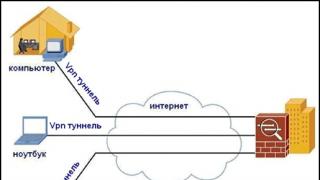
UNIX is not picky about the interface when it comes to system management. A typical way to administer a UNIX server is to work remotely over the network, and (thanks to the Internet) you can move away from the computer as far as you like, as long as the connection is enough reliable for terminal work. This means that all other possibilities of interaction between a machine and a person are understood by the system as resource, which should be distributed among user tasks in the same way as RAM, disk space, or, say, resources printing subsystems.Recall the three problems that operating environment regarding resources: unification, separation And accounting access. With unification, everything is more or less clear: there are many graphic devices in the world, the management of which at a low level is not a task for the user at all, especially since each type of device is controlled in its own way. Low level commands the system must take over, and the user must provide graphic primitives(like the line drawing function) that will always work the same way.
It turns out that it is not enough for the user of this resource to represent the graphics adapter as a large page of video memory, partially displayed on the output device - the monitor: after all, it is not enough for the user of the disk to represent it as an array of sectors! The difference is that this would not be enough for the system itself, so UNIX introduced the concept file system, whose objects are much more complex than "sector" or "disk". As for graphics, UNIX doesn't have any preferences or particular views on these machine abilities. This means that it is reasonable for the system to organize access to device, and the required object model let implements a custom task.
Such a task will, of course, be different from user utilities and software products. In her rights, she would rather be akin to demons. It will receive sole access to the device, and in relation to the user it will itself become an operating environment, organizing in your own way unification, separation and accounting of access to graphic resources in the object model. Therefore, the whole complex of programs for working with graphic devices is usually called graphics subsystem.
A doubling of functions is inevitable: the system deals with authentication and authorization - and graphics subsystem forced to do the same, since she is charged with the duty to "divide". Moreover, unlike the same file system, the very concept resource sharing graphical input or output seems, to put it mildly, non-obvious. How to share a mouse between users? monitor screen? Apparently, we have to admit that this sides graphics subsystem there is one person, but to which subjects belong programs who use it, graphics subsystem unknown. It is generally strange to talk about accounting for graphic resources, however, as we will see later, there is some rational grain in this, and the UNIX approach allows using it.