In order to repair an LCD monitor with your own hands, you must first understand what main electronic components and blocks this device consists of and what each element of the electronic circuit is responsible for. Beginning radio mechanics at the beginning of their practice believe that success in repairing any device lies in the availability of a circuit diagram of a specific device. But in fact, this is a misconception and a circuit diagram is not always needed.
So, let’s open the cover of the first LCD monitor that comes to hand and in practice we will understand its structure.
LCD monitor. Main functional blocks.
The LCD monitor consists of several functional blocks, namely:
LCD panel
The liquid crystal panel is a complete device. As a rule, the assembly of an LCD panel is carried out by a specific manufacturer, who, in addition to the liquid crystal matrix itself, embeds into the LCD panel fluorescent backlight lamps, frosted glass, polarizing color filters and an electronic decoder board that generates voltages from digital RGB signals to control the gates of thin-film transistors (TFTs). ).
Consider the composition of the LCD panel of a computer monitor ACER AL1716. The LCD panel is a complete functional device and, as a rule, there is no need to disassemble it during repairs, with the exception of replacing failed backlight lamps.
LCD panel marking: CHUNGHWA CLAA170EA
On the back of the LCD panel there is a fairly large printed circuit board, to which a multi-pin cable is connected from the main control board. The printed circuit board itself is hidden under a metal strip.
The printed circuit board contains a multi-pin NT7168F-00010 chip. This microcircuit is connected to the TFT matrix and participates in the formation of the image on the display. From the NT7168F-00010 microcircuit there are many pins, which are formed into ten loops under the designation S1-S10. These cables are quite thin and appear to be glued to the printed circuit board on which the NT7168F chip is located.
Control board
The control board is also called the main board ( Main board). The main board houses two microprocessors. One of them is a control 8-bit microcontroller SM5964 with an 8052 core and 64 kB of programmable Flash memory.
The SM5964 microprocessor performs a fairly small number of functions. A button panel and monitor operation indicator are connected to it. This processor controls turning the monitor on/off and starting the backlight inverter. To save user settings, a memory chip is connected to the microcontroller via the I 2 C bus. Typically, these are eight-pin non-volatile memory chips of the series 24LCxx.
The second microprocessor on the control board is the so-called monitor scaler (LCD controller) TSU16AK. This microcircuit has many tasks. It performs most of the functions related to converting and processing the analog video signal and preparing it for submission to the LCD panel.
With regard to an LCD monitor, you need to understand that it is inherently a digital device in which all control of the pixels of the LCD display occurs digitally. The signal coming from the computer's video card is analog and for its correct display on the LCD matrix it is necessary to carry out many transformations. This is what a graphics controller is designed for, or otherwise a monitor scaler or an LCD controller.
The tasks of the LCD controller include such as recalculation (scaling) of images for different resolutions, formation of an OSD menu, processing of analog RGB signals and sync pulses. In the controller, analog RGB signals are converted into digital ones using 3-channel 8-bit ADCs that operate at a frequency of 80 MHz.
The TSU16AK monitor scaler interacts with the SM5964 control microcontroller via a digital bus. To operate the LCD panel, the graphics controller generates synchronization signals, clock frequency and matrix initialization signals.
The TSU16AK microcontroller is connected via a cable to the NT7168F-00010 chip on the LCD panel board.
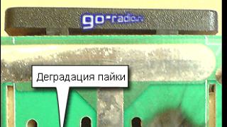
If the graphics controller of the monitor malfunctions, as a rule, defects appear related to the correct display of the image on the display (stripes may appear on the screen, etc.). In some cases, the defect can be eliminated by soldering the scaler leads. This is especially true for monitors that operate around the clock in harsh conditions.
During prolonged operation, heating occurs, which has a bad effect on the quality of soldering. This may cause malfunctions. Defects related to the quality of soldering are not uncommon and are also found in other devices, for example, DVD players. The cause of the malfunction is degradation or poor-quality soldering of multi-pin planar microcircuits.
Power supply and backlight inverter
The most interesting thing to study is the monitor's power supply, since the purpose of the elements and circuitry are easier to understand. In addition, according to statistics, malfunctions of power supplies, especially switching ones, occupy a leading position among all others. Therefore, practical knowledge of the device, element base and circuitry of power supplies will certainly be useful in the practice of repairing radio equipment.
The power supply for the LCD monitor consists of two. The first one is AC/DC adapter or in other words, a network switching power supply (pulse unit). Second - DC/AC inverter . Essentially these are two converters. The AC/DC adapter is used to convert 220 V alternating voltage into a small DC voltage. Typically, voltages from 3.3 to 12 volts are generated at the output of a switching power supply.
The DC/AC inverter, on the contrary, converts direct voltage (DC) into alternating voltage (AC) with a value of about 600 - 700 V and a frequency of about 50 kHz. Alternating voltage is supplied to the electrodes of fluorescent lamps built into the LCD panel.
First, let's look at the AC/DC adapter. Most switching power supplies are built on the basis of specialized controller microcircuits (with the exception of cheap mobile chargers, for example).
So in the power supply of an LCD monitor Acer AL1716 microcircuit applied TOP245Y. Documentation (datasheet) for this chip is easy to find from open sources.
In the documentation for the TOP245Y chip you can find typical examples of circuit diagrams of power supplies. This can be used when repairing power supplies for LCD monitors, since the circuits largely correspond to the standard ones indicated in the description of the microcircuit.
Here are some examples of circuit diagrams of power supplies based on TOP242-249 series microcircuits.
The following circuit uses dual Schottky barrier diodes (MBR20100). Similar diode assemblies (SRF5-04) are used in the Acer AL1716 monitor unit we are considering.
Note that the above circuit diagrams are examples. Actual circuits of pulse blocks may differ slightly.
The TOP245Y microcircuit is a complete functional device, the housing of which contains a PWM controller and a powerful field-effect transistor that switches with a huge frequency from tens to hundreds of kilohertz. Hence the name - switching power supply.
The operating diagram of a switching power supply is as follows:
Rectification of alternating mains voltage 220V.
This operation is performed by a diode bridge and a filter capacitor. After rectification, the voltage on the capacitor is slightly higher than the mains voltage. The photo shows a diode bridge, and next to it is a filtering electrolytic capacitor (82 µF 450 V) - a blue barrel.
Voltage conversion and reduction using a transformer.
Switching with a frequency of several tens - hundreds of kilohertz of direct voltage (>220 V) through the winding of a high-frequency pulse transformer. This operation is performed by the TOP245Y chip. The pulse transformer performs the same role as the transformer in conventional network adapters, with one exception. It operates at higher frequencies, many times higher than 50 hertz.
Therefore, the manufacture of its windings requires a smaller number of turns, and, consequently, less copper. But a core of ferrite is required, and not of transformer steel as in 50 hertz transformers. Those who do not know what a transformer is and why it is used, first read the article about the transformer.
The result is a very compact transformer. It is also worth noting that switching power supplies are very economical and have high efficiency.
Rectification of alternating voltage reduced by a transformer.
This function is performed by powerful rectifier diodes. In this case, diode assemblies labeled SRF5-04 are used.
To rectify high-frequency currents, Schottky diodes and conventional power diodes with p-n junctions are used. Conventional low-frequency diodes for rectifying high-frequency currents are less preferable, but are used for rectifying high voltages (20 - 50 volts). This must be taken into account when replacing defective diodes.
Schottky diodes have some features that you need to know. Firstly, these diodes have a low transition capacitance and are able to quickly switch - go from open to closed state. This property is used to operate at high frequencies. Schottky diodes have a low voltage drop of about 0.2-0.4 volts, versus 0.6 - 0.7 volts for conventional diodes. This property increases their efficiency.
Schottky barrier diodes also have undesirable properties that hinder their wider use in electronics. They are very sensitive to excess reverse voltage. If the reverse voltage is exceeded, the Schottky diode irreversibly fails.
A conventional diode goes into reversible breakdown mode and can recover after exceeding the permissible reverse voltage value. It is this circumstance that is the Achilles heel, which causes the burnout of Schottky diodes in the rectifier circuits of all kinds of switching power supplies. This should be taken into account when carrying out diagnostics and repairs.
To eliminate voltage surges that are dangerous for Schottky diodes and are formed in the transformer windings at the pulse fronts, so-called damping circuits are used. In the diagram it is designated as R15C14 (see Fig. 1).
When analyzing the circuitry of the Acer AL1716 LCD monitor power supply, damping circuits were also found on the printed circuit board, consisting of a 10 Ohm SMD resistor (R802, R806) and a capacitor (C802, C811). They protect Schottky diodes (D803, D805).
It is also worth noting that Schottky diodes are used in low-voltage circuits with a reverse voltage limited to a few tens of volts. Therefore, if a voltage of several tens of volts (20-50) is required, then diodes based on p-n junctions are used. This can be seen if you look at the datasheet for the TOP245 chip, which shows several typical power supply circuits with different output voltages (3.3 V; 5 V; 12 V; 19 V; 48 V).
Schottky diodes are sensitive to overheating. In this regard, they are usually installed on an aluminum radiator to dissipate heat.
You can distinguish a diode based on a pn junction from a diode based on a Schottky barrier by the conventional graphic symbol in the diagram.
Symbol for a diode with a Schottky barrier.
After the rectifier diodes, electrolytic capacitors are installed to smooth out voltage ripples. Next, using the resulting voltages 12 V; 5 V; 3.3 V powers all LCD monitor units.
DC/AC inverter
In terms of its purpose, the inverter is similar to electronic ballasts, which are widely used in lighting technology to power household fluorescent lamps. But, there are significant differences between the electronic ballast and the LCD monitor inverter.
An LCD monitor inverter is usually built on a specialized chip, which expands the range of functions and increases reliability. For example, the backlight inverter of the Acer AL1716 LCD monitor is built on the basis of a PWM controller OZ9910G. The controller chip is mounted on a printed circuit board using planar mounting.
The inverter converts direct voltage, the value of which is 12 volts (depending on the circuit design), into alternating voltage of 600-700 volts and a frequency of 50 kHz.
The inverter controller is capable of changing the brightness of fluorescent lamps. Signals for changing the brightness of the lamps come from the LCD controller. Field-effect transistors or their assemblies are connected to the controller microcircuit. In this case, two assemblies of complementary field-effect transistors are connected to the OZ9910G controller AP4501SD(Only 4501S is indicated on the chip body).
There are also two high-frequency transformers installed on the power supply board, which serve to increase the alternating voltage and supply it to the electrodes of the fluorescent lamps. In addition to the main elements, the board contains all kinds of radio elements that serve to protect against short circuits and lamp malfunctions.
Information on repairing LCD monitors can be found in specialized repair magazines. For example, in the magazine “Repair and Service of Electronic Equipment” No. 1, 2005 (pp. 35 – 40), the device and circuit diagram of the LCD monitor “Rover Scan Optima 153” are discussed in detail.
Among monitor malfunctions, there are quite often those that can be easily fixed with your own hands in a few minutes. For example, the already mentioned Acer AL1716 LCD monitor came to the repair table due to a broken contact of the socket outlet for connecting the power cord. As a result, the monitor turned off spontaneously.
After disassembling the LCD monitor, it was discovered that a powerful spark was formed at the site of the poor contact, traces of which were easy to detect on the printed circuit board of the power supply. A powerful spark was also formed because at the moment of contact the electrolytic capacitor in the rectifier filter is charged. The cause of the malfunction is solder degradation.
 |
| Solder degradation causing monitor failure |
It is also worth noting that sometimes the cause of a malfunction can be a breakdown of the diodes of the rectifier diode bridge.
The image is formed using individual elements, usually through a scanning system. Simple devices (electronic watches, phones, players, thermometers, etc.) can have a monochrome or 2-5 color display. The multicolor image is generated using 2008) in most desktop monitors based on TN- (and some *VA) matrices, as well as in all laptop displays, matrices with 18-bit color (6 bits per channel) are used, 24-bit is emulated with flickering and dithering .
LCD monitor device
Subpixel of color LCD display
Each pixel of an LCD display consists of a layer of molecules between two transparent electrodes, and two polarizing filters, the planes of polarization of which are (usually) perpendicular. In the absence of liquid crystals, the light transmitted by the first filter is almost completely blocked by the second.
The surface of the electrodes in contact with the liquid crystals is specially treated to initially orient the molecules in one direction. In a TN matrix, these directions are mutually perpendicular, so the molecules, in the absence of tension, line up in a helical structure. This structure refracts light in such a way that the plane of its polarization rotates before the second filter, and light passes through it without loss. Apart from the absorption of half of the unpolarized light by the first filter, the cell can be considered transparent. If voltage is applied to the electrodes, the molecules tend to line up in the direction of the field, which distorts the screw structure. In this case, elastic forces counteract this, and when the voltage is turned off, the molecules return to their original position. With a sufficient field strength, almost all molecules become parallel, which leads to an opaque structure. By varying the voltage, you can control the degree of transparency. If a constant voltage is applied for a long time, the liquid crystal structure may degrade due to ion migration. To solve this problem, alternating current is used, or changing the polarity of the field each time the cell is addressed (the opacity of the structure does not depend on the polarity of the field). In the entire matrix, it is possible to control each of the cells individually, but as their number increases, this becomes difficult to achieve, as the number of required electrodes increases. Therefore, row and column addressing is used almost everywhere. The light passing through the cells can be natural - reflected from the substrate (in LCD displays without backlighting). But it is more often used; in addition to being independent of external lighting, it also stabilizes the properties of the resulting image. Thus, a full-fledged LCD monitor consists of electronics that processes the input video signal, an LCD matrix, a backlight module, a power supply and a housing. It is the combination of these components that determines the properties of the monitor as a whole, although some characteristics are more important than others.
LCD Monitor Specifications
The most important characteristics of LCD monitors:
- Resolution: Horizontal and vertical dimensions expressed in pixels. Unlike CRT monitors, LCDs have one, “native” physical resolution, the rest are achieved by interpolation.
![]()
Fragment of the LCD monitor matrix (0.78x0.78 mm), enlarged 46 times.
- Point size: the distance between the centers of adjacent pixels. Directly related to physical resolution.
- Screen aspect ratio (format): The ratio of width to height, for example: 5:4, 4:3, 5:3, 8:5, 16:9, 16:10.
- Apparent Diagonal: The size of the panel itself, measured diagonally. The area of displays also depends on the format: a monitor with a 4:3 format has a larger area than one with a 16:9 format with the same diagonal.
- Contrast: the ratio of the brightness of the lightest and darkest points. Some monitors use an adaptive backlight level using additional lamps; the contrast figure given for them (the so-called dynamic) does not apply to a static image.
- Brightness: The amount of light emitted by a display, usually measured in candelas per square meter.
- Response Time: The minimum time it takes for a pixel to change its brightness. Measurement methods are controversial.
- Viewing angle: the angle at which the drop in contrast reaches a given value is calculated differently for different types of matrices and by different manufacturers, and often cannot be compared.
- Matrix type: the technology used to make the LCD display.
- Inputs: (eg DVI, HDMI, etc.).
Technologies

Clock with LCD display
LCD monitors were developed in 1963 at the David Sarnoff Research Center of RCA, Princeton, New Jersey.
The main technologies in the manufacture of LCD displays: TN+film, IPS and MVA. These technologies differ in the geometry of surfaces, polymer, control plate and front electrode. The purity and type of polymer with liquid crystal properties used in specific designs are of great importance.
Response time of LCD monitors designed using SXRD technology. Silicon X-tal Reflective Display - silicon reflective liquid crystal matrix), reduced to 5 ms. Sony, Sharp and Philips jointly developed PALC technology. Plasma Addressed Liquid Crystal - plasma control of liquid crystals), which combines the advantages of LCD (brightness and richness of colors, contrast) and plasma panels (large viewing angles horizontally, H, and vertically, V, high update speed). These displays use gas-discharge plasma cells as brightness control, and an LCD matrix is used for color filtering. PALC technology allows each display pixel to be addressed individually, meaning unrivaled controllability and image quality.
TN+film (Twisted Nematic + film)
The “film” part in the technology name means an additional layer used to increase the viewing angle (approximately from 90° to 150°). Currently, the prefix “film” is often omitted, calling such matrices simply TN. Unfortunately, a way to improve the contrast and response time for TN panels has not yet been found, and the response time of this type of matrix is currently one of the best, but the contrast level is not.
TN + film is the simplest technology.
The TN+ film matrix works like this: When no voltage is applied to the subpixels, the liquid crystals (and the polarized light they transmit) rotate 90° relative to each other in the horizontal plane in the space between the two plates. And since the polarization direction of the filter on the second plate makes an angle of 90° with the polarization direction of the filter on the first plate, light passes through it. If the red, green and blue sub-pixels are fully illuminated, a white dot will appear on the screen.
The advantages of the technology include the shortest response time among modern matrices, as well as low cost.
IPS (In-Plane Switching)
In-Plane Switching technology was developed by Hitachi and NEC and was intended to overcome the disadvantages of TN+ film. However, although IPS was able to increase the viewing angle to 170°, as well as high contrast and color reproduction, the response time remained at a low level.
At the moment, matrices made using IPS technology are the only LCD monitors that always transmit the full RGB color depth - 24 bits, 8 bits per channel. TN matrices are almost always 6-bit, as is the MVA part.
If no voltage is applied to the IPS matrix, the liquid crystal molecules do not rotate. The second filter is always turned perpendicular to the first, and no light passes through it. Therefore, the display of black color is close to ideal. If the transistor fails, the “broken” pixel for an IPS panel will not be white, as for a TN matrix, but black.
When a voltage is applied, the liquid crystal molecules rotate perpendicular to their initial position and transmit light.
IPS is now being supplanted by technology S-IPS(Super-IPS, Hitachi year), which inherits all the advantages of IPS technology while reducing response time. But, despite the fact that the color of S-IPS panels has approached conventional CRT monitors, contrast still remains a weak point. S-IPS is actively used in panels ranging in size from 20", LG.Philips, NEC remain the only manufacturers of panels using this technology.
AS-IPS- Advanced Super IPS technology (Advanced Super-IPS), was also developed by Hitachi Corporation in the year. The improvements mainly concerned the contrast level of conventional S-IPS panels, bringing it closer to the contrast of S-PVA panels. AS-IPS is also used as the name for LG.Philips monitors.
A-TW-IPS- Advanced True White IPS (Advanced IPS with true white), developed by LG.Philips for the corporation. The increased power of the electric field made it possible to achieve even greater viewing angles and brightness, as well as reduce the interpixel distance. AFFS-based displays are mainly used in tablet PCs, on matrices manufactured by Hitachi Displays.
*VA (Vertical Alignment)
MVA- Multi-domain Vertical Alignment. This technology was developed by Fujitsu as a compromise between TN and IPS technologies. Horizontal and vertical viewing angles for MVA matrices are 160° (on modern monitor models up to 176-178 degrees), and thanks to the use of acceleration technologies (RTC), these matrices are not far behind TN+Film in response time, but significantly exceed the characteristics of the latter in depth of colors and accuracy of their reproduction.
MVA is the successor to VA technology introduced in 1996 by Fujitsu. When the voltage is turned off, the liquid crystals of the VA matrix are aligned perpendicular to the second filter, that is, they do not transmit light. When voltage is applied, the crystals rotate 90° and a light dot appears on the screen. As in IPS matrices, pixels do not transmit light when there is no voltage, so when they fail they are visible as black dots.
The advantages of MVA technology are the deep black color and the absence of both a helical crystal structure and a double magnetic field.
Disadvantages of MVA compared to S-IPS: loss of details in shadows when viewed perpendicularly, dependence of the image color balance on the viewing angle, longer response time.
Analogues of MVA are technologies:
- PVA (Patterned Vertical Alignment) from Samsung.
- Super PVA from Samsung.
- Super MVA from CMO.
MVA/PVA matrices are considered a compromise between TN and IPS, both in cost and consumer qualities.
Advantages and disadvantages

Image distortion on the LCD monitor at a wide viewing angle

Macro photograph of a typical LCD matrix. In the center you can see two defective subpixels (green and blue).
Currently, LCD monitors are the main, rapidly developing direction in monitor technology. Their advantages include: small size and weight compared to CRT. LCD monitors, unlike CRTs, do not have visible flicker, focusing and convergence defects, interference from magnetic fields, or problems with image geometry and clarity. The energy consumption of LCD monitors is 2-4 times less than that of CRT and plasma screens of comparable sizes. The energy consumption of LCD monitors is 95% determined by the power of the backlight lamps or LED backlight matrix. backlight- back light) LCD matrix. In many modern (2007) monitors, to adjust the screen brightness by the user, pulse-width modulation of the backlight lamps with a frequency of 150 to 400 or more Hertz is used. LED backlighting is primarily used in small displays, although in recent years it has been increasingly used in laptops and even desktop monitors. Despite the technical difficulties of its implementation, it also has obvious advantages over fluorescent lamps, for example, a wider emission spectrum, and therefore a wider color gamut.
On the other hand, LCD monitors also have some disadvantages, which are often fundamentally difficult to eliminate, for example:
- Unlike CRTs, they can display a clear image in only one (“standard”) resolution. The rest are achieved by interpolation with loss of clarity. Moreover, resolutions that are too low (for example 320x200) cannot be displayed on many monitors at all.
- Color gamut and color accuracy are lower than those of plasma panels and CRTs, respectively. Many monitors have irreparable unevenness in brightness transmission (stripes in gradients).
- Many LCD monitors have relatively low contrast and black depth. Increasing the actual contrast is often associated with simply increasing the brightness of the backlight, up to uncomfortable levels. The widely used glossy coating of the matrix only affects subjective contrast in ambient lighting conditions.
- Due to strict requirements for constant matrix thickness, there is a problem of uneven color (backlight unevenness).
- The actual image change speed also remains lower than that of CRT and plasma displays. Overdrive technology solves the speed problem only partially.
- The dependence of contrast on viewing angle still remains a significant disadvantage of the technology.
- Mass produced LCD monitors are more vulnerable than CRTs. The matrix unprotected by glass is especially sensitive. If pressed hard, irreversible degradation may occur. There is also the problem of defective pixels.
- Contrary to popular belief, LCD monitor pixels degrade, although the rate of degradation is the slowest of any display technology.
OLED displays are often considered a promising technology that can replace LCD monitors. On the other hand, this technology has encountered difficulties in mass production, especially for large-diagonal matrices.
see also
- Visible screen area
- Anti-glare coating
- en:Backlight
Links
- Information about fluorescent lamps used to backlight the LCD matrix
- Liquid crystal displays (TN + film, IPS, MVA, PVA technologies)
Literature
- Artamonov O. Parameters of modern LCD monitors
- Mukhin I. A. How to choose an LCD monitor? . "Computer Business Market", No. 4 (292), January 2005, pp. 284-291.
- Mukhin I. A. Development of liquid crystal monitors. “BROADCASTING Television and radio broadcasting”: part 1 - No. 2(46) March 2005, p.55-56; Part 2 - No. 4(48) June-July 2005, pp. 71-73.
- Mukhin I. A. Modern flat-panel display devices."BROADCASTING Television and Radio Broadcasting": No. 1(37), January-February 2004, p.43-47.
- Mukhin I. A., Ukrainsky O. V. Methods for improving the quality of television images reproduced by liquid crystal panels. Materials of the report at the scientific and technical conference “Modern Television”, Moscow, March 2006.
The “heart” of any liquid crystal monitor is the LCD matrix (Liquid Cristall Display). The LCD panel is a complex multilayer structure. A simplified diagram of a color TFT LCD panel is shown in Fig. 2.
The operating principle of any liquid crystal screen is based on the property of liquid crystals to change (rotate) the plane of polarization of light passing through them in proportion to the voltage applied to them. If a polarizing filter (polarizer) is placed in the path of polarized light passing through liquid crystals, then by changing the voltage applied to the liquid crystals, you can control the amount of light transmitted by the polarizing filter. If the angle between the planes of polarization of the light passing through the liquid crystals and the light filter is 0 degrees, then the light will pass through the polarizer without loss (maximum transparency), if it is 90 degrees, then the light filter will transmit a minimum amount of light (minimum transparency).
Thus, using liquid crystals, it is possible to produce optical elements with a variable degree of transparency. In this case, the level of light transmission of such an element depends on the voltage applied to it. Any LCD screen on a computer monitor, laptop, tablet or TV contains from several hundred thousand to several million of these cells, fractions of a millimeter in size. They are combined into an LCD matrix and with their help we can form an image on the surface of a liquid crystal screen.
Liquid crystals were discovered at the end of the 19th century. However, the first display devices based on them appeared only in the late 60s of the 20th century. The first attempts to use LCD screens in computers were made in the eighties of the last century. The first liquid crystal monitors were monochrome and were much inferior in image quality to cathode ray tube (CRT) displays. The main disadvantages of the first generations of LCD monitors were:
- - low performance and image inertia;
- - “tails” and “shadows” in the image from the elements of the picture;
- - poor image resolution;
- - black and white or color image with low color depth;
- - and so on.
However, progress did not stand still and, over time, new materials and technologies were developed in the manufacture of liquid crystal monitors. Advances in microelectronics technology and the development of new substances with liquid crystal properties have significantly improved the performance of LCD monitors.
Design and operation of TFT LCD matrix.
One of the main achievements was the invention of LCD TFT matrix technology - liquid crystal matrix with thin film transistors (Thin Film Transistors). TFT monitors have dramatically increased pixel speed, increased image color depth, and managed to get rid of “tails” and “shadows.”
The structure of the panel manufactured using TFT technology is shown in Fig. 2
A full-color image on an LCD matrix is formed from individual dots (pixels), each of which usually consists of three elements (subpixels) responsible for the brightness of each of the main components of color - usually red (R), green (G) and blue (B) - RGB. The monitor's video system continuously scans all subpixels of the matrix, recording a charge level proportional to the brightness of each subpixel into the storage capacitors. Thin Film Transistors (Thin Film Trasistor (TFT) - in fact, that’s why the TFT matrix is called that) connect storage capacitors to the data bus at the time information is written to a given subpixel and switch the storage capacitor to charge conservation mode for the rest of the time.
The voltage stored in the memory capacitor of the TFT matrix acts on the liquid crystals of a given subpixel, rotating the plane of polarization of light passing through them from the backlight by an angle proportional to this voltage. Having passed through a cell with liquid crystals, the light enters a matrix light filter, on which a light filter of one of the primary colors (RGB) is formed for each subpixel. The pattern of the relative positions of dots of different colors is different for each type of LCD panel, but this is a separate topic. Next, the generated light flux of primary colors enters an external polarizing filter, the light transmittance of which depends on the polarization angle of the light wave incident on it. A polarizing filter is transparent to those light waves whose plane of polarization is parallel to its own plane of polarization. As this angle increases, the polarizing filter begins to transmit less and less light, up to a maximum attenuation at an angle of 90 degrees. Ideally, a polarizing filter should not transmit light polarized orthogonally to its own plane of polarization, but in real life, a small portion of the light does pass through. Therefore, all LCD displays have insufficient black depth, which is especially pronounced at high backlight brightness levels.
As a result, in an LCD display, the light flux from some subpixels passes through a polarizing filter without loss, from other subpixels it is attenuated by a certain amount, and from some subpixels it is almost completely absorbed. Thus, by adjusting the level of each primary color in individual subpixels, it is possible to obtain a pixel of any color shade from them. And from many colored pixels, create a full-screen color image.
The LCD monitor made it possible to make a major breakthrough in computer technology, making it accessible to a large number of people. Moreover, without an LCD screen it would be impossible to create portable computers such as laptops and netbooks, tablets and cell phones. But is everything so rosy with the use of liquid crystal displays? Read on to learn about their advantages and disadvantages...
Creating an LCD Display
The first working liquid crystal display was created by Fergason in 1970. Previously, LCD devices consumed too much power, had a limited service life, and had poor image contrast. The new LCD display was introduced to the public in 1971 and then it received warm approval. Liquid crystals are organic substances that can change the amount of light transmitted under voltage. A liquid crystal monitor consists of two glass or plastic plates with a suspension between them. The crystals in this suspension are arranged parallel to each other, thereby allowing light to penetrate the panel. When an electric current is applied, the arrangement of the crystals changes and they begin to block the passage of light. LCD technology has become widespread in computers and projection equipment. The first liquid crystals were characterized by their instability and were not suitable for mass production. The real development of LCD technology began with the invention by English scientists of a stable liquid crystal - biphenyl. The first generation of liquid crystal displays can be seen in calculators, electronic games and watches. Modern LCD monitors are also called flat panels, active matrix dual scanning, thin film transistors. The idea of LCD monitors has been in the air for more than 30 years, but the research carried out did not lead to acceptable results, so LCD monitors did not gain a reputation for providing good image quality. Now they are becoming popular - everyone likes their elegant appearance, slim figure, compactness, efficiency (15-30 watts), in addition, it is believed that only wealthy and serious people can afford such luxury
Characteristics of LCD monitors
Types of LCD monitors

Monitor Composite Layers
There are two types of LCD monitors: DSTN (dual-scan twisted nematic) and TFT (thin film transistor), also called passive and active matrices, respectively. Such monitors consist of the following layers: a polarizing filter, a glass layer, an electrode, a control layer, liquid crystals, another control layer, an electrode, a glass layer and a polarizing filter. The first computers used eight-inch (diagonally) passive black-and-white matrices. With the transition to active matrix technology, the screen size has increased. Almost all modern LCD monitors use thin-film transistor panels, which provide bright, clear images of a much larger size.
Monitor resolution
The size of the monitor determines the workspace it occupies and, importantly, its price. Despite the established classification of LCD monitors depending on the diagonal size of the screen (15-, 17-, 19-inch), a more correct classification is by operating resolution. The fact is that, unlike CRT-based monitors, the resolution of which can be changed quite flexibly, LCD displays have a fixed set of physical pixels. That is why they are designed to work with only one resolution, called working. Indirectly, this resolution also determines the diagonal size of the matrix, however, monitors with the same operating resolution may have different matrix sizes. For example, 15- to 16-inch monitors generally have a working resolution of 1024 x 768, which means that a given monitor actually physically contains 1024 horizontal pixels and 768 vertical pixels. The operating resolution of the monitor determines the size of the icons and fonts that will be displayed on the screen. For example, a 15-inch monitor can have a working resolution of both 1024 x 768 and 1400 x 1050 pixels. In the latter case, the physical dimensions of the pixels themselves will be smaller, and since the same number of pixels is used when forming a standard icon in both cases, then at a resolution of 1400×1050 pixels the icon will be smaller in its physical dimensions. For some users, too small icon sizes with a high monitor resolution may be unacceptable, so when purchasing a monitor you should immediately pay attention to the working resolution. Of course, the monitor is capable of displaying images in a different resolution than the working one. This mode of monitor operation is called interpolation. In the case of interpolation, the image quality leaves much to be desired. The interpolation mode significantly affects the quality of display of screen fonts.
Monitor interface
LCD monitors by their nature are digital devices, so the “native” interface for them is the DVI digital interface, which can have two types of convectors: DVI-I, which combines digital and analog signals, and DVI-D, which transmits only a digital signal. It is believed that the DVI interface is more preferable for connecting an LCD monitor to a computer, although connection via a standard D-Sub connector is also allowed. The DVI interface is also supported by the fact that in the case of an analog interface, double conversion of the video signal occurs: first, the digital signal is converted to analog in the video card (DAC conversion), which is then transformed into a digital signal by the electronic unit of the LCD monitor itself (ADC conversion), As a result, the risk of various signal distortions increases. Many modern LCD monitors have both D-Sub and DVI connectors, which allows you to simultaneously connect two system units to the monitor. You can also find models that have two digital connectors. Inexpensive office models mostly have only a standard D-Sub connector.
LCD matrix type
The basic component of the LCD matrix is liquid crystals. There are three main types of liquid crystals: smectic, nematic and cholesteric. According to their electrical properties, all liquid crystals are divided into two main groups: the first includes liquid crystals with positive dielectric anisotropy, the second - with negative dielectric anisotropy. The difference lies in how these molecules react to an external electric field. Molecules with positive dielectric anisotropy are oriented along the field lines, and molecules with negative dielectric anisotropy are oriented perpendicular to the field lines. Nematic liquid crystals have positive dielectric anisotropy, while smectic liquid crystals, on the contrary, have negative dielectric anisotropy. Another remarkable property of LC molecules is their optical anisotropy. In particular, if the orientation of the molecules coincides with the direction of propagation of plane-polarized light, then the molecules do not have any effect on the plane of polarization of the light. If the orientation of the molecules is perpendicular to the direction of propagation of light, then the plane of polarization is rotated so as to be parallel to the direction of orientation of the molecules. The dielectric and optical anisotropy of LC molecules makes it possible to use them as a kind of light modulators, allowing the formation of the required image on the screen. The principle of operation of such a modulator is quite simple and is based on changing the plane of polarization of light passing through the LCD cell. The LCD cell is located between two polarizers, the polarization axes of which are mutually perpendicular. The first polarizer cuts out plane-polarized radiation from the light passing from the backlight lamp. If there were no LC cell, then such plane-polarized light would be completely absorbed by the second polarizer. An LCD cell placed in the path of transmitted plane-polarized light can rotate the plane of polarization of the transmitted light. In this case, part of the light passes through the second polarizer, that is, the cell becomes transparent (fully or partially). Depending on how the rotation of the plane of polarization in the LC cell is controlled, several types of LC matrices are distinguished. So, an LCD cell placed between two crossed polarizers allows the transmitted radiation to be modulated, creating gradations of black and white color. To obtain a color image, it is necessary to use three color filters: red (R), green (G) and blue (B), which, when installed in the path of white light, will allow you to obtain three basic colors in the required proportions. So, each pixel of an LCD monitor consists of three separate sub-pixels: red, green and blue, which are controlled LCD cells and differ only in the filters used, installed between the top glass plate and the output polarizing filter
Classification of TFT-LCD displays
The main technologies in the manufacture of LCD displays: TN+film, IPS (SFT) and MVA. These technologies differ in the geometry of the surfaces, polymer, control plate and front electrode. The purity and type of polymer with liquid crystal properties used in specific developments are of great importance.
TN matrix

TN cell structure
A TN-type (Twisted Nematic) liquid crystal matrix is a multilayer structure consisting of two polarizing filters, two transparent electrodes and two glass plates, between which the actual nematic liquid crystal substance with positive dielectric anisotropy is located. Special grooves are applied to the surface of the glass plates, which makes it possible to create an initially identical orientation of all liquid crystal molecules along the plate. The grooves on both plates are mutually perpendicular, so the layer of liquid crystal molecules between the plates changes its orientation by 90°. It turns out that LC molecules form a spirally twisted structure (Fig. 3), which is why such matrices are called Twisted Nematic. Glass plates with grooves are located between two polarizing filters, and the polarization axis in each filter coincides with the direction of the grooves on the plate. In its normal state, an LCD cell is open because the liquid crystals rotate the plane of polarization of light passing through them. Therefore, plane-polarized radiation generated after passing through the first polarizer will also pass through the second polarizer, since its polarization axis will be parallel to the polarization direction of the incident radiation. Under the influence of the electric field created by transparent electrodes, the molecules of the liquid crystal layer change their spatial orientation, lining up along the direction of the field lines. In this case, the liquid crystal layer loses the ability to rotate the plane of polarization of the incident light, and the system becomes optically opaque, since all the light is absorbed by the output polarizing filter. Depending on the applied voltage between the control electrodes, it is possible to change the orientation of the molecules along the field not completely, but only partially, that is, to regulate the degree of twist of the LC molecules. This, in turn, allows you to change the intensity of the light passing through the LCD cell. Thus, by installing a backlight lamp behind the LCD matrix and changing the voltage between the electrodes, you can vary the degree of transparency of one LCD cell. TN matrices are the most common and cheapest. They have certain disadvantages: not very large viewing angles, low contrast and the inability to obtain perfect black color. The fact is that even when the maximum voltage is applied to the cell, it is impossible to completely spin the LC molecules and orient them along the field lines. Therefore, such matrices remain slightly transparent even when the pixel is completely turned off. The second drawback is related to small viewing angles. To partially eliminate it, a special scattering film is applied to the surface of the monitor, which allows you to increase the viewing angle. This technology is called TN+Film, which indicates the presence of this film. Finding out exactly what type of matrix is used in the monitor is not so easy. However, if there is a “broken” pixel on the monitor resulting from the failure of the transistor that controls the LCD cell, then in TN matrices it will always light up brightly (red, green or blue), since for a TN matrix an open pixel corresponds to a lack of voltage on the cell. You can recognize a TN matrix by looking at the black color at maximum brightness - if it is more gray than black, then it is probably a TN matrix.
IPS matrices

IPS cell structure
Monitors with an IPS matrix are also called Super TFT monitors. A distinctive feature of IPS matrices is that the control electrodes are located in the same plane on the bottom side of the LCD cell. In the absence of voltage between the electrodes, the LC molecules are located parallel to each other, the electrodes, and the polarization direction of the lower polarizing filter. In this state, they do not affect the polarization angle of the transmitted light, and the light is completely absorbed by the output polarizing filter, since the polarization directions of the filters are perpendicular to each other. When voltage is applied to the control electrodes, the generated electric field rotates the LC molecules by 90° so that they are oriented along the field lines. If light is passed through such a cell, then due to the rotation of the plane of polarization, the upper polarizing filter will transmit light without interference, that is, the cell will be in the open state (Fig. 4). By varying the voltage between the electrodes, it is possible to force the LC molecules to rotate at any angle, thereby changing the transparency of the cell. In all other respects, IPS cells are similar to TN matrices: a color image is also formed through the use of three color filters. IPS matrices have both advantages and disadvantages compared to TN matrices. The advantage is the fact that in this case the color is perfectly black, and not gray, as in TN matrices. Another undeniable advantage of this technology is the large viewing angles. The disadvantages of IPS matrices include a longer pixel response time than for TN matrices. However, we will return to the issue of pixel reaction time later. In conclusion, we note that there are various modifications of IPS matrices (Super IPS, Dual Domain IPS) that can improve their characteristics.
MVA matrices
Domain structure of an MVA cell
MVA is a development of VA technology, that is, technology with vertical molecular ordering. Unlike TN and IPS matrices, in this case liquid crystals with negative dielectric anisotropy are used, which are oriented perpendicular to the direction of the electric field lines. In the absence of voltage between the plates of the LC cell, all liquid crystal molecules are oriented vertically and have no effect on the plane of polarization of transmitted light. Since the light passes through two crossed polarizers, it is completely absorbed by the second polarizer and the cell is in a closed state, while, unlike the TN matrix, it is possible to obtain a perfectly black color. When a voltage is applied to the electrodes located above and below, the molecules rotate 90°, orienting themselves perpendicular to the electric field lines. When plane-polarized light passes through such a structure, the plane of polarization rotates by 90° and the light passes freely through the output polarizer, that is, the LC cell is in the open state. The advantages of systems with vertical ordering of molecules are the ability to obtain ideal black color (which, in turn, affects the ability to obtain high-contrast images) and short pixel response time. In order to increase viewing angles, systems with vertical ordering of molecules use a multidomain structure, which leads to the creation of MVA-type matrices. The idea behind this technology is that each subpixel is divided into several zones (domains) using special protrusions, which slightly change the orientation of the molecules, forcing them to align with the surface of the protrusion. This leads to the fact that each such domain shines in its own direction (within a certain solid angle), and the totality of all directions expands the viewing angle of the monitor. The advantages of MVA matrices include high contrast (due to the ability to obtain perfectly black color) and large viewing angles (up to 170°). Currently, there are several varieties of MVA technology, for example PVA (Patterned Vertical Alignment) from Samsung, MVA-Premium, etc., which further enhance the characteristics of MVA matrices.
Brightness
Today, in LCD monitors, the maximum brightness stated in the technical documentation ranges from 250 to 500 cd/m2. And if the brightness of the monitor is high enough, then this is necessarily indicated in advertising brochures and presented as one of the main advantages of the monitor. However, this is precisely where one of the pitfalls lies. The paradox is that it is impossible to rely on the numbers indicated in the technical documentation. This applies not only to brightness, but also to contrast, viewing angles and pixel response time. Not only may they not correspond to actual observed values at all, but sometimes it is even difficult to understand what these numbers mean. First of all, there are different measurement techniques described in different standards; Accordingly, measurements carried out using different methods give different results, and you are unlikely to be able to find out exactly what method and how the measurements were carried out. Here's one simple example. The measured brightness depends on the color temperature, but when they say that the monitor brightness is 300 cd/m2, the question arises: at what color temperature is this maximum brightness achieved? Moreover, manufacturers indicate brightness not for the monitor, but for the LCD matrix, which is not at all the same thing. To measure brightness, special reference generator signals with a precisely specified color temperature are used, so the characteristics of the monitor itself as a final product may differ significantly from those stated in the technical documentation. But for the user, the characteristics of the monitor itself, and not the matrix, are of paramount importance. Brightness is a really important characteristic for an LCD monitor. For example, if the brightness is insufficient, you are unlikely to be able to play various games or watch DVD movies. In addition, it will be uncomfortable to work at the monitor in daylight conditions (external illumination). However, it would be premature to conclude on this basis that a monitor with a declared brightness of 450 cd/m2 is somehow better than a monitor with a brightness of 350 cd/m2. Firstly, as already noted, declared and real brightness are not the same thing, and secondly, it is quite enough for the LCD monitor to have a brightness of 200-250 cd/m2 (not declared, but actually observed). In addition, the way in which the brightness of the monitor is adjusted is also important. From a physics point of view, brightness adjustment can be done by changing the brightness of the backlight. This is achieved either by adjusting the discharge current in the lamp (in monitors, Cold Cathode Fluorescent Lamps, CCFLs are used as backlights), or by so-called pulse-width modulation of the lamp power supply. With pulse-width modulation, voltage is supplied to the backlight lamp in pulses of a certain duration. As a result, the backlight lamp does not glow constantly, but only at periodically repeating time intervals, but due to the inertia of vision, it seems that the lamp is constantly on (the pulse repetition rate is more than 200 Hz). Obviously, by changing the width of the supplied voltage pulses, you can adjust the average brightness of the backlight. In addition to adjusting the brightness of the monitor using the backlight, sometimes this adjustment is carried out by the matrix itself. In fact, a DC component is added to the control voltage at the electrodes of the LCD cell. This allows the LCD cell to open completely, but does not allow it to close completely. In this case, as the brightness increases, the black color ceases to be black (the matrix becomes partially transparent even when the LCD cell is closed).
Contrast
An equally important characteristic of an LCD monitor is its contrast, which is defined as the ratio of the brightness of the white background to the brightness of the black background. Theoretically, the contrast of the monitor should not depend on the brightness level set on the monitor, that is, at any brightness level, the measured contrast should have the same value. Indeed, the brightness of the white background is proportional to the brightness of the backlight. Ideally, the ratio of the light transmittance of an LCD cell in the open and closed state is a characteristic of the LCD cell itself, but in practice this ratio may depend on both the set color temperature and the set brightness level of the monitor. Recently, the image contrast on digital monitors has increased significantly, and now this figure often reaches 500:1. But here everything is not so simple. The fact is that contrast can be specified not for the monitor, but for the matrix. However, as experience shows, if the passport indicates a contrast of more than 350:1, then this is quite enough for normal operation.
Viewing angle
The maximum viewing angle (both vertical and horizontal) is defined as the angle from which the image contrast in the center is at least 10:1. Some matrix manufacturers, when determining viewing angles, use a contrast ratio of 5:1 rather than 10:1, which also introduces some confusion into the technical specifications. The formal definition of viewing angles is quite vague and, most importantly, has no direct bearing on the correct color rendering when viewing an image at an angle. In fact, for users, a much more important circumstance is the fact that when viewing an image at an angle to the surface of the monitor, it is not a drop in contrast that occurs, but color distortions. For example, red turns into yellow, and green turns into blue. Moreover, such distortions manifest themselves differently in different models: in some they become noticeable even at a slight angle, much smaller than the viewing angle. Therefore, it is fundamentally wrong to compare monitors based on viewing angles. It is possible to compare, but such a comparison has no practical significance.
Pixel response time

Typical pixel turn-on timing diagram for a TN+Film matrix

Typical pixel turn-off timing diagram for a TN+Film matrix
Reaction time, or pixel response time, is usually indicated in the technical documentation for the monitor and is considered one of the most important characteristics of the monitor (which is not entirely true). In LCD monitors, the pixel response time, which depends on the type of matrix, is measured in tens of milliseconds (in new TN+Film matrices, the pixel response time is 12 ms), and this leads to blurring of the changing picture and can be noticeable to the eye. A distinction is made between pixel on and off time. The pixel on time refers to the period of time required to open the LCD cell, and the off time refers to the period of time required to close it. When we talk about the reaction time of a pixel, we mean the total time the pixel turns on and off. The time a pixel turns on and the time it turns off can vary significantly. When they talk about the pixel response time indicated in the technical documentation for the monitor, they mean the response time of the matrix, not the monitor. In addition, the pixel response time indicated in the technical documentation is interpreted differently by different matrix manufacturers. For example, one of the options for interpreting the time to turn a pixel on (off) is that this is the time the pixel brightness changes from 10 to 90% (from 90 to 10%). Until now, when talking about measuring pixel response time, it is assumed that we are talking about switching between black and white colors. If there are no issues with black (the pixel is simply closed), then the choice of white is not obvious. How will a pixel's response time change if measured as it switches between different halftones? This question is of great practical importance. The fact is that switching from a black background to a white one, or vice versa, is relatively rare in real applications. In most applications, transitions between halftones are usually implemented. And if the switching time between black and white colors turns out to be less than the switching time between grayscale, then the pixel response time will not have any practical significance and you cannot rely on this characteristic of the monitor. What conclusion can be drawn from the above? Everything is very simple: the pixel response time declared by the manufacturer does not allow us to clearly judge the dynamic characteristics of the monitor. It is more correct in this sense to speak not about the time a pixel switches between white and black colors, but about the average time a pixel switches between halftones.
Number of colors displayed
All monitors by their nature are RGB devices, that is, the color in them is obtained by mixing in various proportions the three basic colors: red, green and blue. Thus, each LCD pixel consists of three color subpixels. In addition to the completely closed or completely open state of the LCD cell, intermediate states are also possible when the LCD cell is partially open. This allows you to form a color shade and mix the color shades of the base colors in the desired proportions. In this case, the number of colors reproduced by the monitor theoretically depends on how many color shades can be formed in each color channel. Partial opening of the LCD cell is achieved by applying the required voltage level to the control electrodes. Therefore, the number of reproducible color shades in each color channel depends on how many different voltage levels can be applied to the LCD cell. To generate an arbitrary voltage level, you will need to use DAC circuits with a large bit capacity, which is extremely expensive. Therefore, modern LCD monitors most often use 18-bit DACs and less often - 24-bit ones. When using an 18-bit DAC, there are 6 bits per color channel. This allows you to generate 64 (26=64) different voltage levels and, accordingly, obtain 64 color shades in one color channel. In total, by mixing color shades of different channels, it is possible to create 262,144 color shades. When using a 24-bit matrix (24-bit DAC circuit), each channel has 8 bits, which makes it possible to generate 256 (28=256) color shades in each channel, and in total such a matrix reproduces 16,777,216 color shades. At the same time, for many 18-bit matrices the data sheet indicates that they reproduce 16.2 million color shades. What is the matter here and is this possible? It turns out that in 18-bit matrices, through all sorts of tricks, you can bring the number of color shades closer to what is reproduced by real 24-bit matrices. To extrapolate color tones in 18-bit matrices, two technologies (and combinations thereof) are used: dithering and FRC (Frame Rate Control). The essence of dithering technology is that the missing color shades are obtained by mixing the closest color shades of neighboring pixels. Let's look at a simple example. Let's assume that a pixel can only be in two states: open and closed, with the closed state of the pixel producing black, and the open state producing red. If instead of one pixel we consider a group of two pixels, then, in addition to black and red, we can also obtain an intermediate color, thereby extrapolating from a two-color mode to a three-color one. As a result, if initially such a monitor could generate six colors (two for each channel), then after such dithering it will already reproduce 27 colors. The dithering scheme has one significant drawback: an increase in color shades is achieved by reducing the resolution. In fact, this increases the pixel size, which can have a negative impact when drawing image details. The essence of FRC technology is to manipulate the brightness of individual subpixels by additionally turning them on/off. As in the previous example, a pixel is considered to be either black (off) or red (on). Each subpixel is commanded to turn on at a frame rate, that is, at a frame rate of 60 Hz, each subpixel is commanded to turn on 60 times per second. This allows the color red to be generated. If you force the pixel to turn on not 60 times per second, but only 50 (at every 12th clock cycle, turn the pixel off rather than turn it on), then the resulting brightness of the pixel will be 83% of the maximum, which will allow the formation of an intermediate color shade of red. Both color extrapolation methods discussed have their drawbacks. In the first case, there is a possible flickering of the screen and a slight increase in reaction time, and in the second, there is the possibility of loss of image details. It is quite difficult to distinguish an 18-bit matrix with color extrapolation from a true 24-bit matrix by eye. At the same time, the cost of a 24-bit matrix is much higher.
Operating principle of TFT-LCD displays
The general principle of image formation on the screen is well illustrated in Fig. 1. But how to control the brightness of individual subpixels? It is usually explained to beginners this way: behind each subpixel there is a liquid crystal shutter. Depending on the voltage applied to it, it transmits more or less light from the backlight. And everyone immediately imagines some kind of dampers on small hinges that rotate to the desired angle... something like this:
In reality, of course, everything is much more complicated. There are no material flaps on the hinges. In a real liquid crystal matrix, the luminous flux is controlled something like this:
The light from the backlight (we follow the picture from bottom to top) first passes through the lower polarizing filter (white shaded plate). Now this is no longer an ordinary stream of light, but a polarized one. Then the light passes through translucent control electrodes (yellow plates) and encounters a layer of liquid crystals on its way. By changing the control voltage, the polarization of the light flux can be changed by up to 90 degrees (in the picture on the left), or left unchanged (right there). Attention, the fun is about to begin! After the layer of liquid crystals, light filters are located and here each subpixel is colored in the desired color - red, green or blue. If we look at the screen with the top polarizing filter removed, we will see millions of glowing subpixels - and each one glows with maximum brightness, because our eyes cannot distinguish the polarization of light. In other words, without the top polarizer we will simply see a uniform white glow over the entire surface of the screen. But as soon as you put the upper polarizing filter in place, it will “reveal” all the changes that liquid crystals have made to the polarization of light. Some subpixels will remain brightly glowing, like the left one in the figure, whose polarization was changed by 90 degrees, and some will go out, because the upper polarizer is in antiphase to the lower one and does not transmit light with the default polarization. There are also subpixels with intermediate brightness - the polarization of the light flow passing through them was rotated not by 90, but by a smaller number of degrees, for example, by 30 or 55 degrees.
Advantages and disadvantages
|
Symbols: (+) advantage, (~) acceptable, (-) disadvantage |
||
| LCD monitors
| CRT monitors
|
|
| Brightness | (+) from 170 to 250 cd/m2 | (~) from 80 to 120 cd/m2 |
| Contrast | (~) 200:1 to 400:1 | (+) from 350:1 to 700:1 |
| Viewing angle (by contrast) | (~) 110 to 170 degrees | (+) over 150 degrees |
| Viewing angle (by color) | (-) from 50 to 125 degrees | (~) over 120 degrees |
| Permission | (-) Single resolution with fixed pixel size. Optimally can only be used in this resolution; Depending on the supported expansion or compression functions, higher or lower resolutions can be used, but they are not optimal. | (+) Various resolutions are supported. With all supported resolutions, the monitor can be used optimally. The limitation is imposed only by the acceptability of the regeneration frequency. |
| Vertical frequency | (+) Optimal frequency 60 Hz, which is enough to avoid flickering | (~) Only at frequencies above 75 Hz there is no clearly noticeable flicker |
| Color registration errors | (+) no | (~) 0.0079 to 0.0118 inches (0.20 - 0.30 mm) |
| Focusing | (+) very good | (~) from satisfactory to very good> |
| Geometric/linear distortion | (+) no | (~) possible |
| Broken pixels | (-) up to 8 | (+) no |
| Input signal | (+) analog or digital | (~) analog only |
| Scaling at different resolutions | (-) is absent or interpolation methods that do not require large overheads are used | (+) very good |
| Color Accuracy | (~) True Color is supported and the required color temperature is simulated | (+) True Color is supported and there are a lot of color calibration devices on the market, which is a definite plus |
| Gamma correction (color adjustment to the characteristics of human vision) | (~) satisfactory | (+) photorealistic |
| Uniformity | (~) often the image is brighter at the edges | (~) often the image is brighter in the center |
| Color purity/color quality | (~) good | (+) high |
| Flicker | (+) no | (~) not noticeable above 85 Hz |
| Inertia time | (-) from 20 to 30 ms. | (+) negligible |
| Image formation | (+) The image is formed by pixels, the number of which depends only on the specific resolution of the LCD panel. The pixel pitch depends only on the size of the pixels themselves, but not on the distance between them. Each pixel is individually shaped for superior focus, clarity and definition. The image is more complete and smooth | (~) Pixels are formed by a group of dots (triads) or stripes. The pitch of a point or line depends on the distance between points or lines of the same color. As a result, the sharpness and clarity of the image is highly dependent on the size of the dot pitch or line pitch and on the quality of the CRT |
| Energy consumption and emissions | (+) There are practically no dangerous electromagnetic radiations. Power consumption is approximately 70% lower than standard CRT monitors (25 to 40 W). | (-) Electromagnetic radiation is always present, but the level depends on whether the CRT meets any safety standard. Energy consumption in operating condition is 60 - 150 W. |
| Dimensions/weight | (+) flat design, light weight | (-) heavy design, takes up a lot of space |
| Monitor interface | (+) Digital interface, however, most LCD monitors have a built-in analog interface for connecting to the most common analog outputs of video adapters | (-) Analog interface |


Literature
- A.V.Petrochenkov “Hardware-computer and peripherals”, -106 page ill.
- V.E. Figurnov “IBM PC for the user”, -67 pages.
- “HARD "n" SOFT" (computer magazine for a wide range of users) No. 6 2003.
- N.I. Gurin “Working on a personal computer,” - 128 pages.
Let's look at the design of an LCD module for a 19-inch monitor using the example of an LCD module with a TN+Film matrix from the well-known Taiwanese manufacturer HannStar. These modules were used in monitors under the brands Acer, LG, HP, etc.

Under the protective metal cover there are matrix controls located on one board.

through the connector designated CN1, LVDS low-voltage differential signaling signals and +5V supply voltage are supplied to the matrix control board

The controller is responsible for processing LVDS signals from the scaler on the matrix control board

the controller generates signals that, through decoders fused into the cables, control the TFT (Thin film transistor) field-effect transistors of the subpixels of the matrix

in the following image you can see how the subpixels of the matrix are arranged, alternating in the order R-G-B (red-green-blue)

the liquid crystals of each subpixel are controlled by a separate field-effect transistor, that is, in a matrix with a resolution of 1280x1024 there are 1280x1024 = 13010720 pixels, and each pixel in turn consists of three subpixels, thus, the number of transistors in a matrix with a resolution of 1280x1024 is 3932160.
Without going into details of the polarization of the light flux, in a simplified way, you can imagine in general how the LCD matrix works like this: if you apply voltage to the subpixel transistor, then the subpixel will NOT transmit light, if you do not apply voltage, the subpixel will transmit light. If all three RGB subpixels transmit light, then we will see a white dot (pixel) on the screen, if all three subpixels do NOT transmit light, then we will see a black dot on the screen. Depending on the intensity of the light flux (i.e. on the angle of rotation of the liquid crystals in the subpixel) passing through three RGB filters of one pixel, we can get a point of any color

A converter made on the U200 integrated circuit is responsible for generating the necessary supply voltages for the TFT matrix.

If you remove the metal frame and separate the LCD matrix from the reflector/light guide, you will find that the matrix is almost transparent

Let's look at the design of the light guide/diffuser. a plastic frame fixes three films (two scattering and one polarizing between them) on the surface of the light guide, which is a rectangular plexiglass plate ~10mm thick


under the light guide there is a white plastic substrate, 0.5 mm thick

on the side of the light guide facing the white plastic substrate, a special pattern is applied to create uniform illumination at all points of the display

The final piece of the diffuser/light guide “pie” is a metal base; this base contains fastening elements with which the entire LCD module is fixed in the monitor body

high-voltage gas-discharge CCFL (Cold cathode fluorescent lamps) lamps are located in twos, horizontally above and below the light guide

The reflector is several millimeters longer than the larger side of the light guide plate, and also serves as a container, thanks to which the lamps are fixed at the top and bottom of the light guide

Thanks to the special pattern of the light guide, the light of the lamps is distributed evenly over the entire area of the screen. There are other diffuser designs without a heavy light guide plate, and lamps located horizontally from top to bottom with a single pitch behind the LCD matrix. There are diffuser/light guide (backlight) designs using more lamps, for example 6, 8, 12
Important!
This material is intended for informational purposes only. If you do not have sufficient experience in restoring LCD devices, do not disassemble your monitor; as a result of incorrect actions, you may damage the LCD module