People who love good music probably know about the Hi-End tube amplifier. You can make it yourself if you know how to use a soldering iron and have some knowledge of working with radio engineering.
Unique device
Hi-End tube amplifiers are a special class of household appliances. What is it connected with? Firstly, they have a rather interesting design and architecture. In this model, a person can see everything that he needs. This makes the device truly unique. Secondly, the performance of the Hi-End tube amplifier differs from alternative models that use the Hi-End difference in that a minimum number of parts are used during installation. Also, when evaluating the sound of this unit, people trust their ears more than the harmonic distortion measurements and the oscilloscope.
Selection of circuits for assembly
The preamplifier is fairly easy to assemble. For it, you can choose any suitable scheme and start assembling. Another case is the output stage, that is, the power amplifier. As a rule, a lot of different questions arise with him. The output stage has several assembly types and operating modes.
The first type is the single-ended model, which is considered a standard cascade. When operating in the "A" mode, it has a small non-linear distortion, but, unfortunately, has a rather poor efficiency. Also note the average power output. If you need to fully sound a fairly large room, you will need to use a push-pull power amplifier. This model can work in the "AB" mode.
In a single-cycle circuit, only two parts are enough for a good operation of the device: a power amplifier and a preamplifier. The push-pull model already uses a phase-inverted amplifier or driver.
Of course, for two types of output stage, in order to work comfortably with , it is necessary to match the high interelectrode resistance and the low resistance of the device itself. This can be done with a transformer.
If you are a connoisseur of "tube" sound, you should understand that you need to use a rectifier, which is produced on a kenotron, to achieve such a sound. In this case, semiconductor parts must not be used.
When developing a Hi-End tube amplifier, you can not use complex circuits. If you need to sound a fairly small room, then you can use a simple single-cycle design that is easier to make and set up.
DIY Hi-End tube amplifier
Before starting installation, you need to understand some rules for assembling such devices. We will need to apply the basic principle of mounting lamp fixtures - minimizing fixtures. What does it mean? You will need to discard the mounting wires. Of course, this cannot be done everywhere, but their number must be minimized.

In Hi-End, mounting petals and strips are used. They are used as additional points. Such an assembly is called hinged. You will also need to solder the resistors and capacitors that are on the lamp panels. It is strongly discouraged to use printed circuit boards and assemble conductors in such a way that parallel lines are obtained. Thus, the assembly will look chaotic.
Interference elimination
Later, you need to eliminate the low-frequency background, if, of course, it is present. Also important is the choice of grounding point. In this case, you can apply one of the options:
- The type of connection is a star, in which all "earth" conductors are connected to one point.
- The second way is laying a thick copper bus. It is necessary to solder the corresponding elements on it.
In general, it is better to find a grounding point yourself. This can be done by determining the level of low-frequency background by ear. To do this, you need to gradually close all the grids of lamps that are located on the ground. If, when the subsequent contact is closed, the low-frequency background level decreases, then you have found a suitable lamp. To achieve the desired result, it is necessary to experimentally eliminate unwanted frequencies. You also need to apply the following measures to improve the quality of your assembly:
- To make the filament circuits of radio tubes, you need to use twisted wire.
- The tubes used in the preamplifier must be covered with earthed caps.
- It is also necessary to ground cases with variable resistors.
If you want to power the preamp tubes, you can use direct current. Unfortunately, this requires the connection of an additional unit. The rectifier will violate the standards of a Hi-End tube amplifier, as it is a solid state device, which we will not use.
transformers
Another important point is the use of various transformers. As a rule, power and output are used, which must be connected perpendicularly. In this way, you can reduce the level of low-frequency background. Transformers should be located in earthed casings. It must be remembered that the cores of each of the transformers should also be grounded. It is not necessary to apply when you install devices, so that additional problems do not appear. Of course, these are not all the features associated with installation. There are quite a lot of them, and it will not be possible to consider them all. When installing a Hi-End (tube amplifier), you cannot use new element bases. They are now used to connect transistors and integrated circuits. But in our case, they do not fit.
Resistors
A high-quality Hi-End tube amplifier is a retro device. Of course, the details for its assembly must be appropriate. Instead of a resistor, a carbon and wire element may be suitable. If you spare no expense to develop this device, you should use precision resistors, which are quite expensive. Otherwise, MLT models are applicable. This is a pretty good item, as evidenced by the reviews.
Hi-end tube amplifiers are also applicable with BC resistors. They were made about 65 years ago. Finding such an element is quite simple, just take a walk through the radio market. If you use a resistor with a power of more than 4 watts, you need to choose enameled wire elements.
Capacitors
When installing a tube amplifier, you should use different types of capacitors for the system itself and the power supply. They are usually used for tone control. If you want to get high-quality and natural sound, you should use a decoupling capacitor. In this case, a small leakage current appears, which allows you to change the operating point of the lamp.

This type of capacitor is connected to the anode circuit, through which a large voltage flows. In this case, it is necessary to connect a capacitor that supports a voltage of more than 350 volts. If you want to use quality elements, you need to use Jensen parts. They differ from analogues in that their price exceeds 3,000 rubles, and the price of the highest quality radio elements reaches 10,000 rubles. If you use domestic elements, it is better to choose between the K73-16 and K40U-9 models.
Single Ended Amplifier
If you want to apply a one-cycle model, you must first consider its circuit. It includes several components:
- power unit;
- final cascade;
- a pre-amplifier in which you can adjust the tone.
Assembly
Let's start with the pre-amplifier. Its installation takes place according to a fairly simple scheme. It is also necessary to provide for power control and a separator for tone control. It must be tuned to low and high frequencies. To increase the shelf life, you need to apply a multi-band equalizer.

In the laughter of the pre-amplifier, one can see similarities with the common 6N3P double triode. The element we need can be assembled in a similar way, but using the final cascade. This is also repeated in stereo. Remember that the design must be assembled on a circuit board. First it needs to be debugged, and then it can be installed on the chassis. If you have installed everything correctly, the device should turn on immediately. The next step is to move on to the settings. The value of the anode voltage for different types of lamps will be different, so you will need to select it yourself.
Components
If you do not want to use a high-quality capacitor, then you can use K73-16. It is suitable if the operating voltage is more than 350 volts. But the sound quality will be noticeably worse. Electrolytic capacitors are also suitable for this voltage. You need to connect an S1-65 oscilloscope to the amplifier and apply a signal that will pass from the audio frequency generator. At the initial connection, you need to set the input signal to about 10 mV. If you need to know the gain, you will need to use the output voltage. To find the average ratio between low and high frequencies, it is necessary to choose the capacitance of the capacitor.
You can see a photo of the Hi-End tube amplifier below. For this model, 2 lamps with an octal base were used. A double triode is connected to the input, which is connected in parallel. The final stage for this model is assembled on a 6P13S beam tetrode. A triode is mounted in this element, which allows you to get a good sound.

To set up and check the performance of the assembled device, you must use a multimeter. If you want to get more accurate values, then you should use a sound generator with an oscilloscope. When you have taken the appropriate devices, you can proceed to the setting. On the cathode L1 we indicate a voltage of about 1.4 volts, this can be done if you use the resistor R3. The output lamp current must be specified as 60 mA. To make a resistor R8, you need to install a pair of MLT-2 resistors in parallel. Other resistors can be of different types. It should be noted a rather important component - a decoupling capacitor C3. It was not in vain mentioned, since this capacitor has a strong influence on the sound of the device. Therefore, it is better to use a proprietary radio element. The other elements of C5 and C6 are film capacitors. They allow you to increase the quality of transmission of various frequencies.

A power supply built on a 5Ts3S kenotron is worth finding. It complies with all the rules for constructing the device. A homemade Hi-End tube power amplifier will have high-quality sound if you find this item. Of course, otherwise it is worth looking for an alternative. In this case you can use 2 diodes.
For a Hi-End tube amplifier, you can use the appropriate transformer, which was used in old tube technology.

Conclusion
To make a Hi-End tube amplifier with your own hands, you must perform all the steps consistently and accurately. First, connect the power supply with an amplifier. If you set up these devices correctly, you can mount a preamplifier. Also, using the appropriate technique, you can check all the elements in order to prevent breakage. After assembling all the elements together, you can begin to design the device. Plywood might work well for the body. To create a standard model, it is necessary to place radio tubes and transformers on top, and regulators can already be mounted on the front wall. With them, you can amplify the tone and see the power indicator.
I found a great option to upgrade the home audio system "amplifier + DAC". Cheap, convenient. And it is suitable for any stereo systems - from shelf speakers (desktop speakers) to vacuum plugs for a smartphone.
"Lampu" - to the masses! Give distortion to every desktop!
Warm tube sound - is it true?
I like music. And, as a musician, I highly appreciate tube equipment. Not at all for the unique clear sound, as many might think.
An analog (tube) player outputs a "signal + noise" set. Moreover, if noise can be a separable component for transistor audio systems, then tube circuits do not separate the wheat from the chaff, amplifying (or distorting) the entire recording. Where it gets to the amplifier - from a digital or analog source - there is no difference. This is the very “shade” that lovers appreciate so much.
What gives the listener such an approach to sound processing? A lot of distortion and that very unique sound that appears on digital audio circuits during equalization. In fact - the noise of the elements (circuit, transformer, recording itself) and inaccuracy. But this inaccuracy is soft, smooth (this is how the lamp works, smoothing out sharp signal transitions).
On the other hand, transistor amplifier circuits give the listener a lot of additional, extra sounds. If explained to a wide user, the essence is as follows: each amplifier in operation “doubles” (not quite so, but it will be clearer) a sound wave (each one!), And transmits to the listener with a lower volume and time lag. 
The number of such takes for analog and transistor devices is different. If a tube amplifier, on average, generates no more than 3 additional waves with a sharp drop in volume, then a transistor one generates up to 20, distinct and often audible, almost less than the original sound wave.
Another feature of the "tube sound" is the compression built into the circuit during overload. The transistor, digital circuit at some point begins to wheeze or cuts hard, clips extra frequencies. The "lamp" itself cuts off what will lead to unnecessary distortion when overloaded. Soft and pleasant.
Moreover, those distortions that appear when the sound is amplified also behave differently. In tube technology, they are proportional to the loudness (output power). In digital, the greatest distortion appears at the minimum and maximum.
Finally, the most pleasant feature. When the tube amplifier overheats, the same distortion appears, which is now called the "guitar" lotion. No wonder guitarists choose tube amplifiers: each scheme gives its own sound to the instrument.
When listening to music, this is not so important. But there is a certain equalizing effect that is unique to each analog circuit. And imitating it is incredibly difficult.
I want cheap and cheerful. What are the options?

So, there is certainty with the type of update. But what to buy is always a big question. Modern digital amplifiers offer a ton of cheap but quality options.
Analog systems are now considered the preserve of audiophiles. With all the ensuing problems: “golden” wires, unique power schemes (composed without knowledge of electrical engineering), huge sizes and terrifying price tags.
There are few options left: make it yourself or buy the same huge amplifier from the distant past. However, the latter option can be very interesting if you deal not only with sound, but also with the decoration of the room. In conditions of limited working space, a 20-kilogram unit will be superfluous. And next to modern computer technology, such solutions do not look at all.
The path of a self-made samurai is long and difficult. One day we will touch on this topic. And today we’ll talk about what will happen if a simple analog circuit is ordered in the form of a ready-made amplifier from China. In fact, it will turn out much better than assembling it yourself - at least in the average case. Cheaper and more reliable.
The simplest tube amplifier is assembled on Soviet tubes of the 6zh “X” type, where X is a number from 1 to 12. Depending on the specific number, the sound of the finished device and some tuning conditions that are not critical for the finished product change.
The advantage of this circuit is its incredible simplicity and the ability to abandon a bulky transformer - lamps of this type can be powered not with alternating current, but with direct current! This is where "cheap and cheerful" begins.
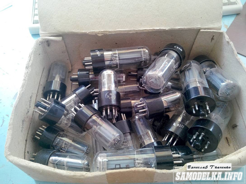
In addition, lamps of this type are still produced (the factory was restored by an American businessman). Yes, and before they were very common: in any market you can buy them in dozens. In addition, they can be replaced with the equally common E180F or 6688. Chinese manufacturers produce many ready-made audio solutions for various purposes based on these lamps.
Combination of retro and modern technologies

I chose LynePAudio A962 as the most affordable and versatile.
So, on board we have:
- output amplifying stage on 2 lamps 6zh9 in Chinese version,
- built-in digital DAC with audio stream decoding 16-32 bits, 44.1/48 kHz,
- ASIO support,
- 2 high-impedance headphone outputs with impedance from 16 to 600 ohms,
- stereo line output to RCA for use as a preamp,
- digital input (USB),
- analog input 3.5 and RCA.
Does it inspire? Still how, because the final power of the amplifier is 1.1 W for a load of 32 Ohms. For a desktop toy, this figure is enough even to shake monitors, not to mention any portable headphones. 
The board is neatly packaged in a beautiful case and can decorate any interior. Especially the desktop. Very cool! And it really saves time - even if you have to modify it later.
The appearance of the LynePAudio A962 is really worth it to buy a finished product, and not bother with a homemade product. Convenience and ease of use is even more important. Enabled - enjoy.
To work with digital audio sources, no drivers or additional software are required (if you do not use a smartphone). The built-in DAC is digital and digests most of the formats coming from a computer or smartphone: it eats up MP3, FLAC, and WAV. However, there is a limitation to 32 bits and 48 kHz. DSD doesn't digest at all. 
If you have a high-quality DAC, you can do without the built-in one. To do this, the LynePAudio A962 has a separate analog input (3.5 mm mini-jack). Not the best solution, but sometimes useful. It works surprisingly stable, but requires a thick wire. Preferably with good shielding.
Power and background: 2 sides of a cheap "lamp"
All these are just flowers. Berries - LynePAudio A962 outputs. A pair of headphone outputs, jack and mini-jack, are connected in one circuit. You can select both, but the resulting power will be divided according to the load (headphone impedance). And even so, this is enough for any desktop headphone options.
The tube stage can operate at full power without serious distortion. It’s even more correct: at peak power, the lamps light up to a red glow, and the sound acquires that very pronounced color. It can be compared to a light, warm fuzz. Yes, the sound is not clear - but that's exactly what we need?
LynePAudio A962 can drive any, even the most high-impedance headphones. Moreover, with sufficient volume for any listener. The main thing is not to unscrew the volume potentiometer to the maximum, so as not to burn the headphones and knock out the eardrums. Average portables with an impedance of 16-32 ohms will require only half the power for the maximum. 
The second output channel turns the LynePAudio A962 into a tube preamp. In this case, its only role is to give color to the sound. And without an additional amplifier, this option will be of little use.
In any case, the sound of this box is exactly what you expect. This is a good tube single-ended headphone amplifier. Not more. But no less. Clear, warm sound and a lot of pleasant impressions. 
Only a complete power supply can spoil it. The fact is that lamps of the 6zh series can be powered by a constant current source. And the Chinese did not fail to take advantage of this. The LynePAudio A962 comes with a conventional 12 V switching power supply, which causes hum.
The background does not depend on the volume, warming up or the way the amplifier is turned on. Either power stabilization is required, or the unit needs to be replaced with a better one. And all the problems disappear, leaving a perfect, warm sound.
Is it worth saving?

The feasibility of buying a cheap tube amplifier seems doubtful. But in fact, with no need for a bulky room stereo system, the difference between a tiny Chinese and an expensive Japanese is not always noticeable.
At least not for the price difference. Single-ended tube amplifiers have many disadvantages, including low power and increased reliance on external noise sources. If you exclude them, you get an almost perfect sound, soft and calm. The same lamp sound.
The simplicity of the circuit makes it easy to modify the LynePAudio A962. And this is perhaps the coolest opportunity. In Russia, it is still easy to find 6g series lamps, and even pick up a pair yourself. Depending on the type of lamp used, the color of the sound changes. Such is the original replacement for the equalizer.
You can buy LynePAudio A962 for only 3100 rubles. An additional set of lamps on the market costs 100 rubles. If you are not yet familiar with table lamp technology, this is a great opportunity to get acquainted.
Today we have a useful homemade product for connoisseurs of good sound: a high-quality do-it-yourself tube amplifier
Hello!
I decided to assemble a push-pull tube amplifier (my hands itch very much) from the parts that I have accumulated over a long long time: case, lamps, panels for them, transformers and so on.
I must say that I got all this stuff for free (tobish free of charge) and the cost of my new project will be 0.00 hryvnia, and if I need to buy something in small things, I’ll buy it for rubles (since I started my project in Ukraine, and I’ll finish already in Russia).
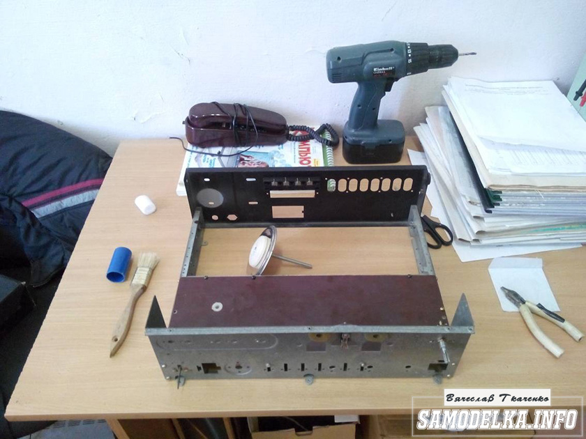
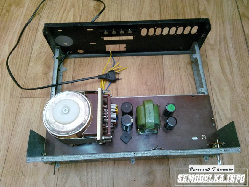
I'll start with the body.
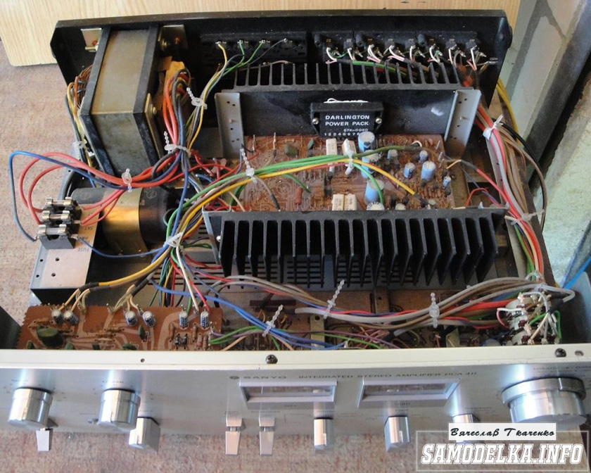
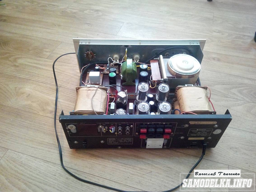
Once upon a time it was, apparently, a good SANYO DCA 411 amplifier.
But I didn’t have a chance to listen to him, because I got it in a terrible dirty and non-working form, it was dug up to the point of being impossible and the burnt 110 V networker (Japanese, probably) smoked all the insides. Instead of native microcircuits of the final stage, some snot from Soviet transistors (this is a photo from the Internet of a good copy). In short, I gutted it all, and began to think. So, I didn’t come up with anything better than to shove a lampovik there (there is quite a lot of space there).
Decision is made. Now we need to decide on the scheme and details. I have enough lamps 6p3s and 6n9s.

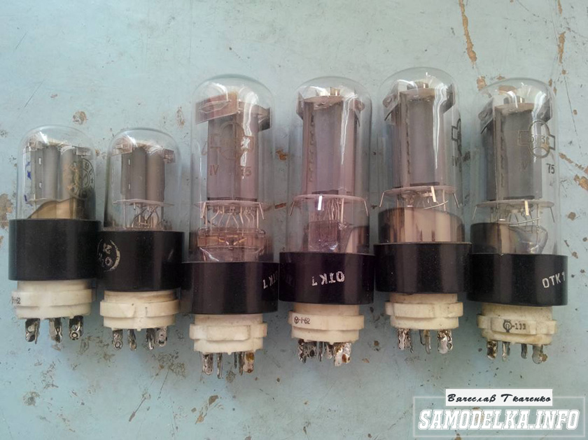
Due to the fact that I already assembled a single-cycle 6p3s, I wanted more power and, after rummaging through the Internet, I chose this 6p3s push-pull amplifier circuit.
Diagram of a homemade tube amplifier (ULF)

The scheme is taken from the site heavil.ru
I must say that the scheme is probably not the best, but in view of its relative simplicity and availability of parts, I decided to dwell on it. Output transformer (an important figure in the plot).
It was decided to use the "legendary" TS-180 as output transformers. Do not throw stones right away (save them until the end of the article :)) I myself have deep doubts about such a decision, but given my desire not to spend a penny on this project, I will continue.
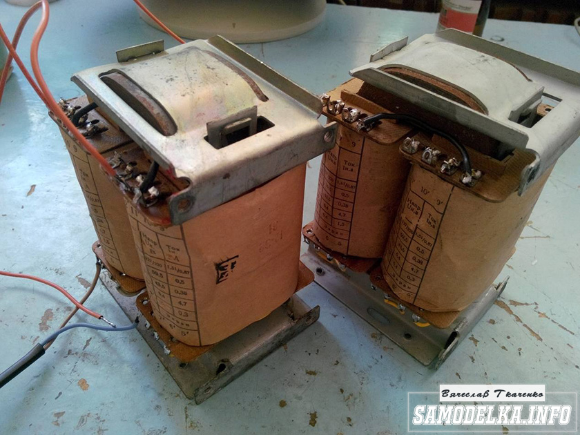
I connected the trance conclusions for my case like this.
(8)—(7)(6)—(5)(2)—(1)(1′)—(2′)(5′)—(6′)(7′)—(8′) primary
(10)—(9)(9′)—(10′) secondary
anode voltage is applied to the connection of terminals 1 and 1', 8 and 8' to the anodes of the lamps.
10 and 10′ per speaker. (I did not come up with this myself, I found it on the Internet). To dispel the fog of pessimism, I decided to check the frequency response of the transformer by eye. To do this, I assembled such a stand in haste.
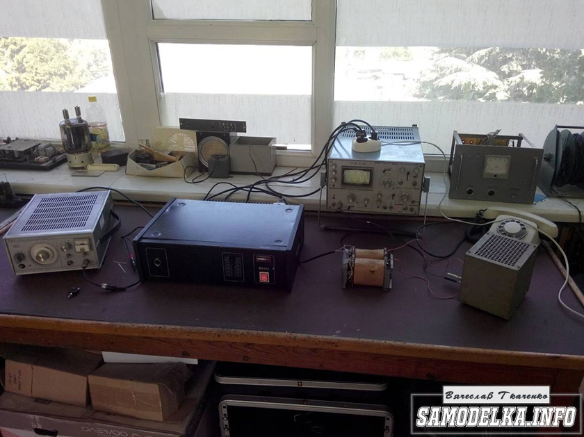
In the photo, the GZ-102 generator, the BEAG APT-100 amplifier (100V-100W), the C1-65 oscilloscope, the load equivalent of 4 ohms (100W), and the transformer itself. By the way, the site has.
I set 1000 Hz with a swing of 80 (approximately) volts and fix the voltage on the oscilloscope screen (about 2 V). Then I increase the frequency and wait for the voltage on the secondary of the trance to begin to drop. I do the same in the direction of decreasing the frequency.
The result, I must say, pleased me. The frequency response is almost linear in the range from 30 Hz to 16 kHz, well, I thought it would be much worse. By the way, the BEAG APT-100 amplifier has a step-up transformer at the output and its frequency response may not be ideal either.
Now you can collect everything to the heap in the case with a clear conscience. There is an idea to make the installation and layout inside in the best traditions of the so-called modding (minimum wires in sight) and it would not be bad to make the backlight with LEDs as in industrial copies.
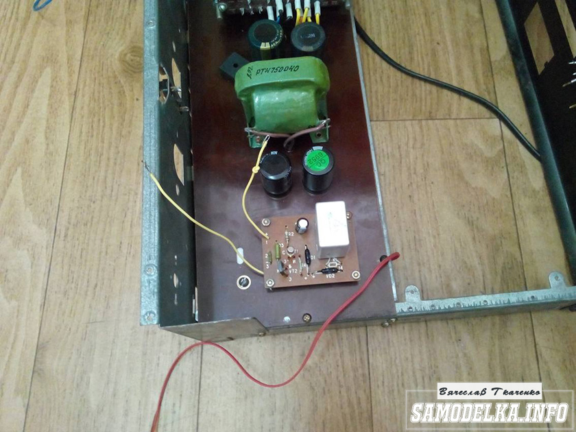
Power supply for a homemade tube amplifier.
I will start the assembly with at the same time I will describe it. The heart of the power supply (and the entire amplifier, probably) will be the TST-143 toroidal transformer, which I at one time (4 years ago) tore with meat from some kind of tube generator right at the time it was being taken to a landfill. Unfortunately, I didn’t manage to do anything more. L, it’s a pity for such a generator, or maybe it was also a worker or it was possible to fix it ... Okay, I digress. Here he is my enforcer.


Of course, I found a diagram for it on the Internet.

The rectifier will be on a diode bridge with a filter on the inductor for anode power. And 12 volts to power the backlight and anode voltage. Throttle I have.

Its inductance was 5 henries (according to the device), which is quite enough for good filtering. And the diode bridge was found like this.

Its name is BR1010. (10 amps 1000 volts). I'm starting to cut out the amplifier. I think it will be something like this.
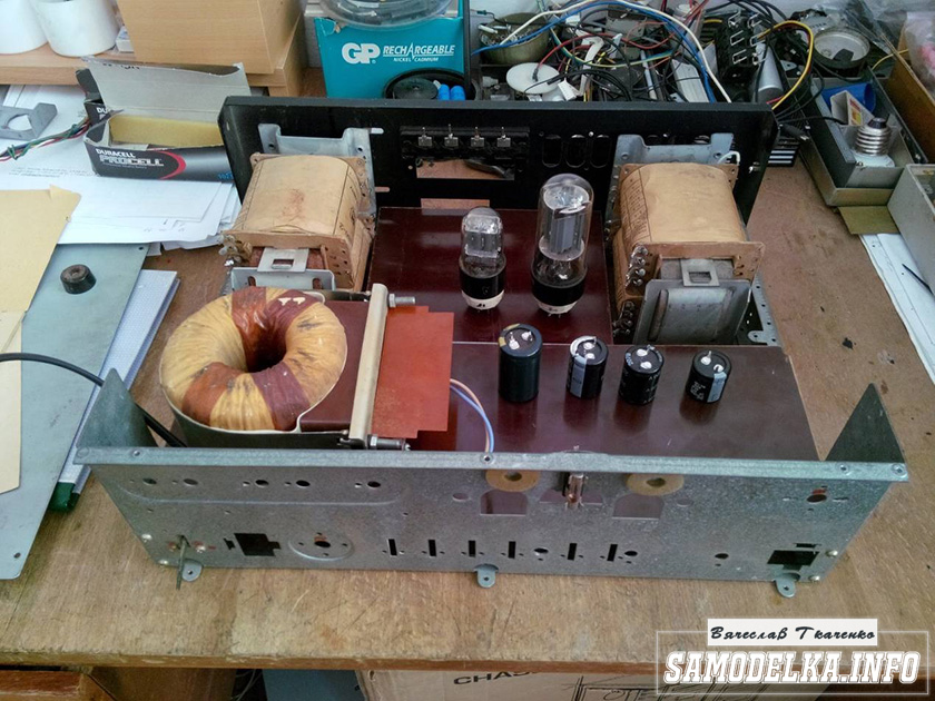
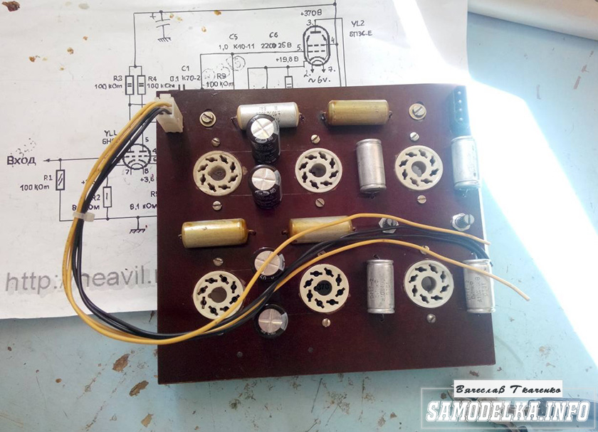
I mark and cut holes in the textolite for panels for light bulbs.
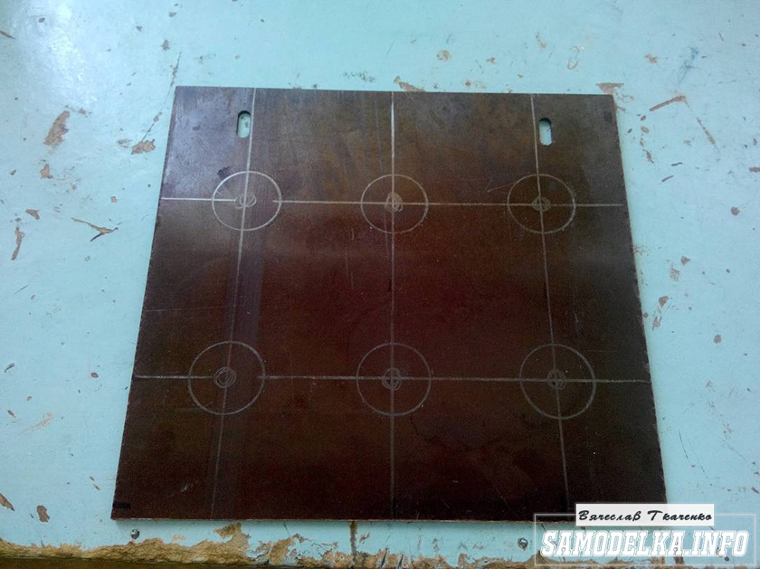


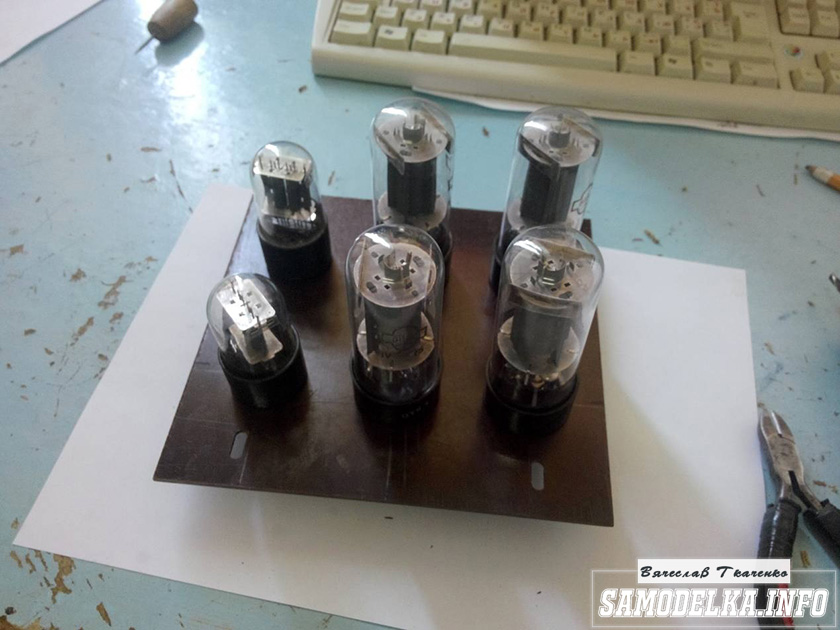


It turns out not bad :) so far I like everything.
And so, and so. drilling sawing :)


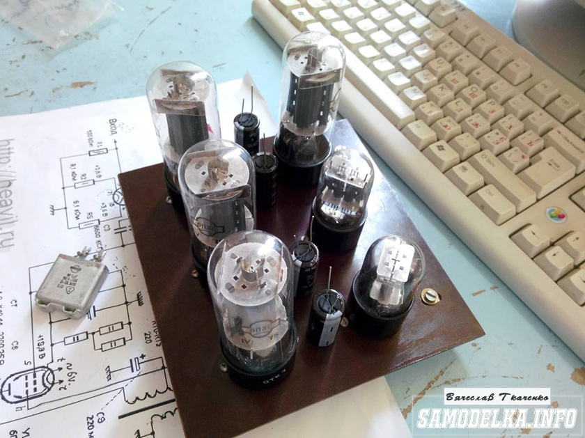
Something began to emerge.

I found a fluoroplastic wire in old stocks and immediately all the alternatives and compromises regarding the wire for installation disappeared without a trace :).


This is how the installation turned out. Everything is as if “kosher” the incandescences are intertwined, the earth is at one, practically, point. Should work.

It's time to fence food. After checking and checking all the output windings of the trance, I soldered all the necessary wires to it, and began to install it according to the accepted plan.

As you know, in our not easy anywhere without materials at hand: the container from the Kinder Surprise came in handy.

And a Nescafe lid and an old CD


I ripped out TV and monitor boards. All capacities are at least 400 volts (I know that I need more, but I don’t want to buy).
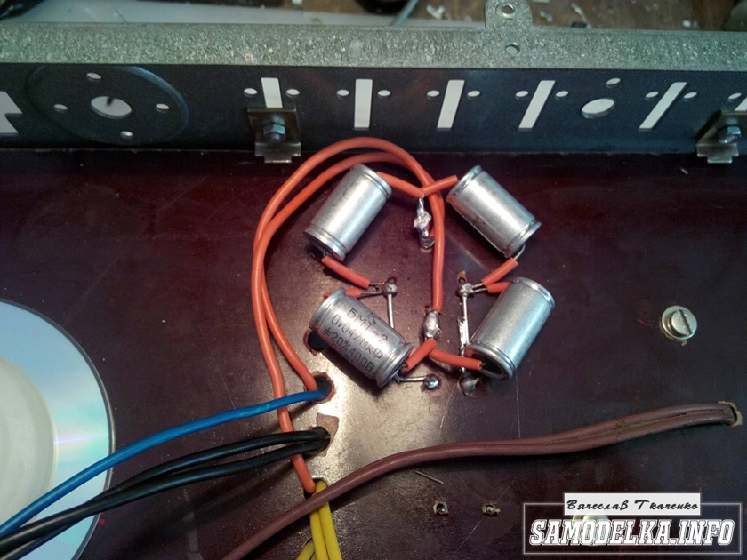
I shunt the bridge with containers (which ones were at hand, I’ll probably change them later)

It turns out a bit too much, but oh well, it will sag under load :)

I use the regular power switch from the amplifier (clear and soft).
Done with this. Well done :)
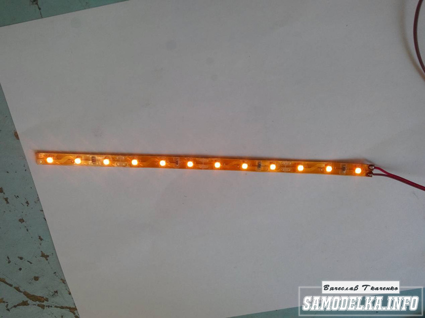
Illumination for the body of the tube amplifier.
To implement the backlight, an LED strip was purchased.
And installed as follows in the case.
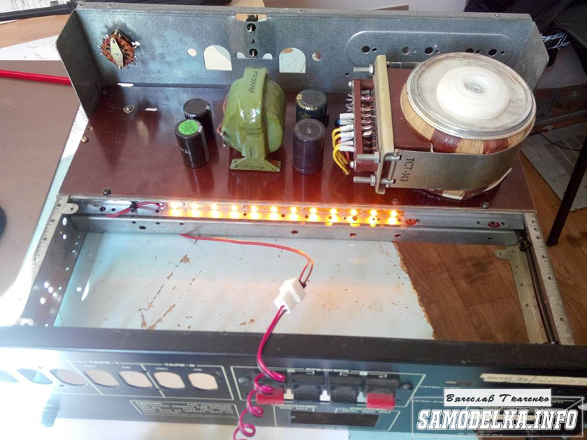

Now the glow of the amplifier will be visible in the daytime. To power the backlight, I will make a separate rectifier with a stabilizer on some kind of KRKEN-like microcircuit (which I can find in the trash), from which I plan to power the anode voltage supply delay circuit.
Delay relay.
Digging through the bins of my homeland, I found just such a completely untouched thing.
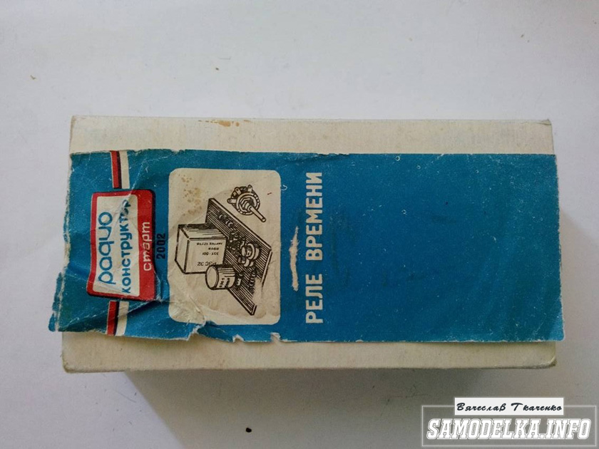
This is a radio time relay kit for a photo enlarger.

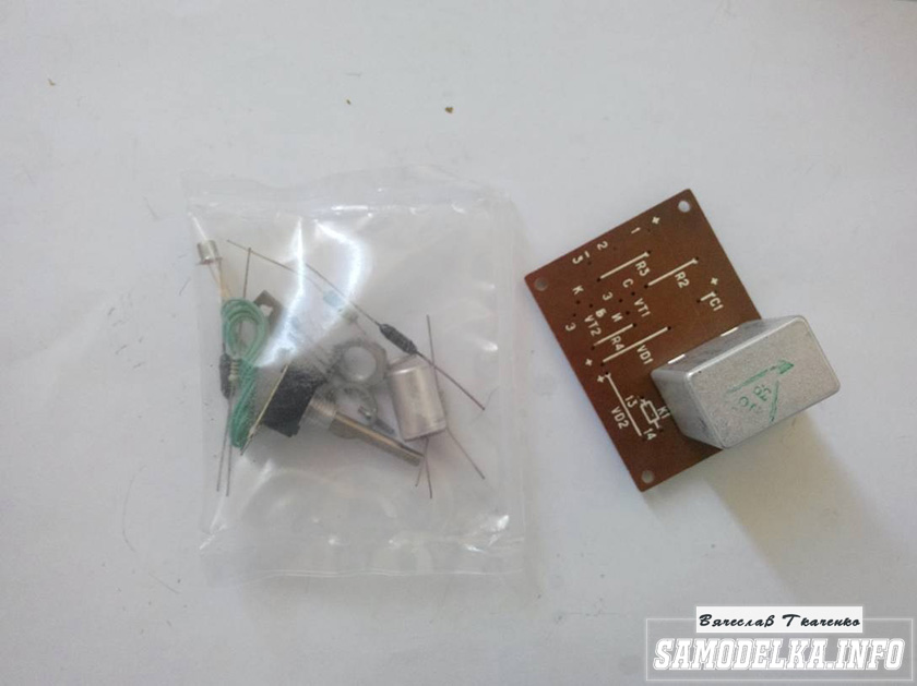
We collect, we check, we try on.


The response time was set to about 40 seconds, and the variable resistor was replaced by a constant one. The case is coming to an end. It remains to put everything together, put the muzzle, indicators and regulators.
Regulators (input variables)
They say that the sound quality can greatly depend on them. In short, I put these
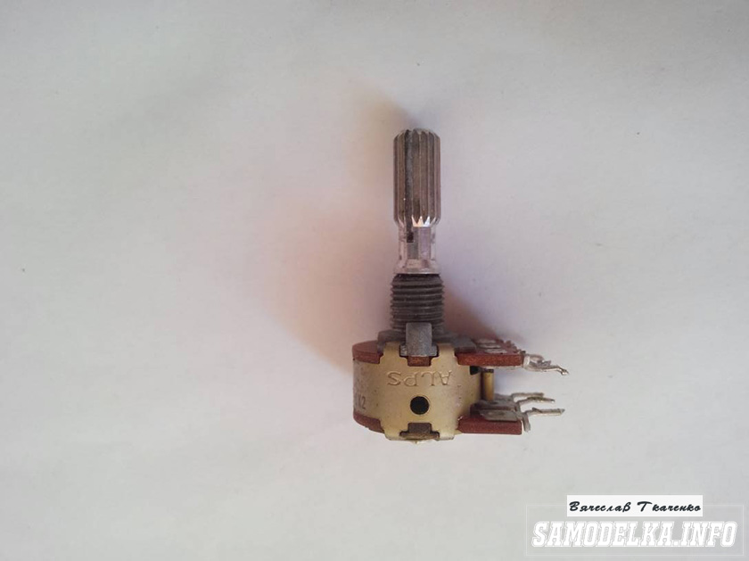
Dual 100 kOhm. since I have two of them, I decided to parallelize the conclusions, thereby obtaining 50 kOhm and increased resistance to wheezing :)
Indicators.
I used standard indicators, with standard illumination

The connection diagram was mercilessly bitten by me from the native board and is also involved.

Here's what I ended up with.
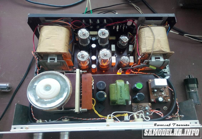


When checking the power, the amplifier showed a voltage at the output of 10 volts of an undistorted sinusoid with a frequency of 1000 Hz to a load of 4 ohms (25 watts) equally across the channels, which pleased :)
When listening, the sound was crystal clear without background and dust, as they say, but too monitor, or what? nice but flat.
I naively thought that he would play without timbres, but ...
When using the software equalizer, we managed to get a very beautiful sound that everyone liked. Thank you all very much!!!
Briefly, mostly photos (re-uploaded in good quality). I must say right away that there was little experience and knowledge in radio engineering, I made many mistakes. Not being a fanatical lover of warm tube sound, I was interested in the assembly process itself.
The hardest part is finding the output transformers. I bought myself ready-made ones from the TU-100M amplifier (I didn’t choose for a long time, I took what they were). The frame was made from an aluminum profile and the margin of safety went a little too far.
The upper part of the case was made of 3mm steel. Holes for transformers and lamps were laser cut. The bottom was also cut out of 2mm steel with ventilation holes:
Front panel made of a piece of aluminum:
Scheme
The final amplifier is assembled according to a push-pull circuit on two G-807 lamps. The preamplifier contains two amplification stages assembled on a 6N9S double triode (foreign analogue 6SL7).Advantages 6N9S:
1) The lamp was originally designed for audio applications;
2) Two triodes in a balloon;
3) High linearity;
4) Wide distribution, low price.
Disadvantages 6H9S:
1) High internal resistance.
The terminal amplifier (an intermediate link between single-ended and push-pull amplifiers) is assembled according to a phase-inverted circuit on a 6N9S double triode, the main purpose is the formation of two mutually antiphase, equal in amplitude signals from the input signal. In the TU-100M circuit, the lamp amplifies the input signal and the voltage amplified by it is supplied to the grid of the lamp of the first arm of the push-pull amplifier.
Part of the output voltage of the first lamp of the phase-inverted amplifier is fed to the input of the second lamp of this amplifier. The voltage amplified by the second lamp of the phase-inverted amplifier is supplied to the grid of the lamp of the second arm of the push-pull
amplifier. Thus, for the first arm of a push-pull amplifier, the signal passes through one lamp, and for the second through two.
It would be better if the voltage applied to the input of the first arm would be equal to the voltage to the input of the second arm. I made a slightly different circuit, with a modified phase-inverted cascade.
Advantages:
1) Reduced requirements for filtering the supply voltage;
2) Extremely low noise level;
3) Equal output voltages of the shoulders.
Found another option on the forums:

Sockets for 6H9S lamps:

A DAC is assembled in the amplifier case with the ability to connect to a computer via USB:


Setup option:

Transformer screens, first sketches on paper:

Cut from 2mm steel: 
After filing and sanding:


Some more photos:


Cleaned up a bit:


Price: unreasonably expensive.
It’s easier to buy ready-made for 4-5 thousand rubles. But if someone needs it, I can throw off the files for cutting and for printed circuit boards.