In the days of huge tube TVs, a good antenna for high-quality analog TV reception was in short supply. Those that could be bought in stores were not of high quality. Therefore, people made UHF television antennas with their own hands. Today, many are interested in homemade devices. And even when digital technologies are everywhere, this interest does not fade away.
Digital era
This era also affected television. Today, T2 broadcasting is developing especially widely. It has its own characteristics. In those places where the signal level slightly exceeds the interference, a fairly high-quality reception is obtained. There is simply no further signal. The digital signal does not care about interference, however, in a situation of cable mismatch or various phase distortions, almost anywhere in the transmitting or receiving path, the picture can go in squares even with a strong signal level.
In modern television, other changes have taken place. So, all broadcasting is carried out in the UHF band, the transmitters have good coverage. The conditions under which radio waves propagate through cities have changed dramatically.
Antenna parameters
Before you start manufacturing, you need to determine some parameters of these structures. They, of course, require in-depth knowledge in various areas of mathematics, as well as the laws of electrodynamics.
So, the gain is the ratio of the power at the input of the reference system to the power at the input of the antenna used. All this will work if each of the antennas creates the values of the intensity and flux density with the same parameters. The value of this coefficient is dimensionless.
The directional factor is the ratio of the field strength that the antenna produces to the field strength in any direction.

It must be remembered that parameters such as KU and KND are not interconnected. There is a UHF antenna for digital TV, which has a very high directivity. However, its enhancement is small. These designs are directed into the distance. There are also designs with high directivity. Here it comes in combination with a very powerful level of amplification.
Today, you can not look for formulas, but use special programs. They already take into account all the necessary parameters. You just have to enter some conditions - and you will receive a complete calculation of the UHF antenna, so that you can then assemble it.
Manufacturing nuances
Any structural element in which signal currents flow must be connected using a soldering iron or a welding machine. Such a node, if it is in the open air, suffers from a breakdown in contact. From this, various antenna parameters and the reception level can become significantly worse.
This is especially true for points with zero potentials. According to experts, voltage can be observed in them, as well as current antinode. To be more precise, this is the maximum current value. Is it available at zero voltages? This is not surprising.
Such places are best made from solid metal. Creeping currents are unlikely to affect the picture if the connections are made by welding. However, due to their presence, the signal may disappear.
How and what to solder?
Do-it-yourself UHF antenna is not very easy to make. This involves working with a soldering iron. Modern television cable manufacturers no longer make it copper. Now there is an inexpensive alloy that is resistant to corrosion. These materials are difficult to solder. And if they are heated long enough, there is a risk of burning the cable.

Experts recommend using low-power soldering irons, low-melting solders, and fluxes. Do not spare the paste when soldering. The solder will lie correctly only if it is under a layer of boiled flux.
Catch T2
In order to enjoy digital TV, it is enough to purchase a special tuner. But it does not have a built-in antenna. And those that are offered as special digital ones are too expensive and meaningless.
Now we will learn how to catch T2 on a completely homemade design. Homemade UHF antenna - it's simple, cheap, high quality. Try it yourself.
The simplest antenna
To assemble this design, you will not even need to go to the store. For its manufacture, a conventional antenna cable is sufficient. You need 530 mm of wire for the ring and 175 mm from which the loop will be made.

The TV antenna itself is a ring of cable. The ends must be stripped, and then connected to the loop. And to the latter you need to solder a cable that connects to the T2 tuner. So, on the ring, the screen and the central core are connected to the screens of the loop. At the last, the central veins are also connected. And the cable to the tuner is soldered as standard to the screen and the central core.
So we got the UHF antenna, made with our own hands. Its construction turned out to be very cheap and practical. And it works no worse than expensive store options. It must be fixed on plywood or plexiglass. For this, construction clamps are perfect.
"People's" antenna
This design is an aluminum disc. The outer diameter of the element should be 365 mm and the inner diameter 170 mm. The disc must be 1 mm thick. First you need to make a cut in the disk (10 mm wide). In the place where he drank, you should install a printed circuit board made of textolite. It should be 1 mm thick.

The board must have holes for the M3 screws. The board must be glued to the disk. Then you need to solder the cable leads to it. The central core should be soldered to one side of the disk, the screen to the other. In terms of quality, such a TV antenna will receive better with two discs, especially if it is far from the TV repeater.
Universal Antenna
Nothing supernatural will be used to make this design. We will make it from various improvised materials. However, although it is homemade, it will work perfectly in the entire decimeter range. So, this UHF antenna, quickly made with your own hands, is in no way inferior to store-bought, more expensive designs. To receive T2, it will be enough completely.

So, to assemble this design, you will need empty cans of canned food or beer. You need 2 cans with a diameter of 7.5 cm. The length of each is 9.5 cm. You also need to stock up on strips of textolite or getinax, always with foil.
Our cans need to be connected to the textolite strips using a soldering iron. The plate of this material, which will connect the containers at the top, must be completely covered with copper foil. On the bottom plate, the foil should be cut. This is done for easy cable connection.
It is necessary to assemble the structure in such a way that the total length is not less than 25 cm. This antenna (UHF band) is a broadband symmetrical vibrator. Due to its surface area, it has large gains.
If suddenly you cannot find suitable jars, then you can use containers with a smaller diameter. However, then the foil will have to be cut on the upper connecting plate as well.
"Beer" antenna
Love to drink beer? Don't throw away cans. You can make a good antenna out of them. To do this, you need to fix two beer cans on any dielectric material.
First you need to choose the right cable, and then bring it to mind. To do this, the cable must be stripped. You will see shielding foil. There will be a protective layer underneath. But under it, you can directly observe the cable.
For our antenna, you need to strip the top layer of this wire by about 10 cm. The foil must be carefully twisted to end up with a branch. The protective layer for the central core must be cleaned by 1 cm.
On the other hand, you need to solder the plug for the TV to the cable. If you were a subscriber of cable networks, then this part and cable will not even have to be purchased separately.
Now for the cans. It is advisable to use beer containers with a volume of 1 liter. However, good German beer in such cans is expensive, and domestic beer is not sold.

Banks must be opened very carefully. Then you need to free the container from the contents, and then dry it well. Next, use a self-tapping screw to connect our screen on the cable and the jar. To the second you need to fasten the central core.
For a better image quality, it is better to connect the containers and the cable with a soldering iron.
It is necessary to fix the banks on some dielectric material. It should be noted that they should be located on the same straight line. The distance between them depends on the capacity. All this is selected only by experience.
Zigzag
The UHF zigzag antenna has the simplest possible design. The item itself is broadband. Its device allows you to allow various deviations from the original design parameters. At the same time, its electrical parameters are almost not violated.
Its input resistance in a certain range depends on the size of the conductors that will form the basis of the web. There is a dependency here. The greater the width or thickness of the conductors, the better the antenna will be matched to the feeder. In general, any conductors can be used to make a web. For this, plates, and tubes, and corners, and much more are suitable.

In order to increase the directivity of such an antenna, it is permissible to use a flat screen, which will play the role of a reflector. The latter will reflect high-frequency energy towards the antenna. Such screens are often large, and the phase depends mainly on the distance.
On the practical side, the reflector is only rarely made from a single sheet of metal. More often it is made in the form of conductors that are connected in the same plane. For design reasons, it is not necessary to make a screen that is too dense. The conductors from which the screen itself will be made are attached by welding or soldering to a metal frame.

This design is made very simply. It works well in the UHF range. In the USSR, it was a real folk irreplaceable model. It has a small size, so it can be used as a UHF indoor antenna.
The material will be copper tubes or aluminum sheet. The side parts can be made of solid metal. Often they are tightened with a net or covered with a tin. If one of the indicated methods is used, then the structure should be soldered along the contour.
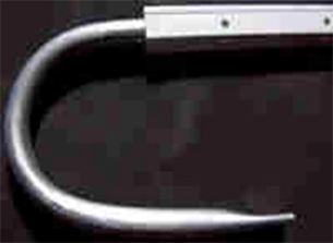
The cable must not be bent sharply. How to carry out this element, you can see in the pictures presented.
It must be guided in such a way that it reaches the side corner, but does not go beyond the antenna or side square.
Indoor antenna MV UHF
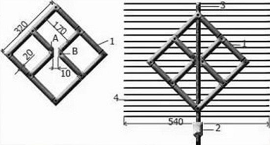
This design is designed for easy and reliable reception of digital television signals. It can be made easily and very quickly. To do this, you need an aluminum or copper bar. Its length should be up to 1800 mm. This antenna can also be used as an outdoor antenna.

The design is a frame in the form of a rhombus. There should be two. One acts as a vibrator, the second works as a reflector. To receive T2, it is necessary that the side of our rhombus is approximately 140 mm, and the distance between them is 100 mm.

After the frame is made and the structure becomes rigid, a dielectric is mounted between the two ends of our rod. It could be anything. Shape and size are completely irrelevant. The distance between two points of the bars should be approximately 20 mm. The upper parts of our rhombuses need to be connected.

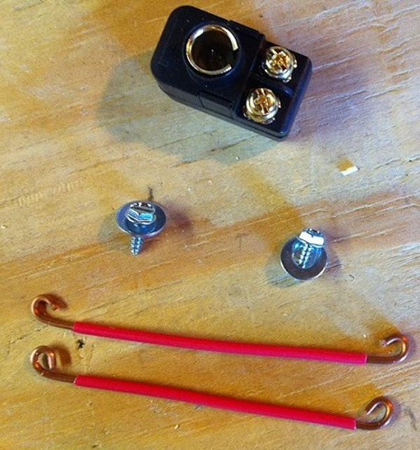
The feeder can be made from a cable. It must be connected to brass or copper petals, which should already be fixed on the antenna output.
If the resulting design does not meet your expectations, for example, poor reception quality or the repeater is far away, you can supply the antenna with an amplifier - and as a result you will get an active UHF antenna. It is used both in the city and in the country.
The simplest UHF loop antenna
This design resembles the number "zero". By the way, this is the coefficient of its amplification. It is ideal for T2 reception. This part is able to work better than the products that are offered in stores.
It is also called digital, because with it you can perfectly catch digital broadcasts. It is narrowband, and this is a significant advantage. It works on the principle of a selective valve, which allows us to talk about reliable protection against interference.

For assembly, you will need an ordinary coaxial cable with a resistance of 75 ohms, as well as a regular TV plug. It is better to choose a cable with a large diameter of all options. As a stand, you can use a cardboard box or something else.
How long the frame will be, we determine using programs for calculating antenna parameters. The material for the manufacture of the frame can be used the same as in the cable. By the way, for calculations you need to know the frequencies of digital broadcasting in your city.

The central core of the cable in the frame design is not needed. The stripped wire is twisted together with the core and braid of the frame. Then this connection must be soldered.
The structure must be placed on a dielectric base. Better to keep it away from your tuner. It is important that there is no voltage at the antenna input.
So, we found out how the UHF antenna is made with our own hands. As you can see, this is not such a difficult task. But now you can watch your favorite TV shows in digital quality. And such a design is installed in the same way as a regular store - on the roof. You can use screws or bolted connection. It should be installed in a safe place so that during gusts of wind it does not fly off along with a piece of slate. It is desirable that the antenna is mounted at the highest possible height. Thus, you will exclude the appearance of interference during the display of cable or digital television.
The modern market offers a huge range of antennas for receiving terrestrial television. There are two main types of these products that allow you to receive the meter and decimeter range of radio. They can also be divided according to the place of use into outdoor and indoor. Fundamentally, they are not much different. Here, first of all, the emphasis is on the size and preservation of the necessary parameters under the influence of weather conditions. In this article, we will discuss the existing types of these products, consider what their parameters are, how to conduct testing. And for lovers of tinkering, we will tell you how a decimeter antenna is made with your own hands.
What's the difference?
Let's try to explain in a nutshell how to determine what kind of product is in front of you. The UHF antenna looks like a ladder. Install them parallel to the ground. Meters are crossed aluminum tubes. The appearance of both types is shown in the photo below. There are also combined antennas, when both the "ladder" and the cross tubes are combined.
Problem of choice
It would seem that everything is simple. However, at the same time, the buyer faces the question of how to choose the right device, what parameters to pay attention to. In general, it is best to test TV antennas directly in the conditions in which they will work. The passage of a radio signal is often individual for a particular area. So, the product in the laboratory shows some results, and in the "field" - completely different. There is a certain tactic that allows you to test both meter and decimeter TV antennas. However, choosing such a product in the store, we are not able to conduct a full test. Not a single seller will agree to give us several different antennas for testing. In this case, you have to trust the characteristics of these products. And hope that the selected antenna will perform its functions according to the passport data, and not real conditions.

main parameters
The decimeter antenna is characterized primarily by the radiation pattern. The main parameters of this characteristic are the level of the side (auxiliary) lobes and the width of the main lobe. The width of the diagram is determined in the horizontal and vertical planes at the level of 0.707 from the largest value. So, according to this parameter (the width of the main lobe), the diagrams are usually divided into non-directional and directional. What does this mean? If the main lobe has a narrow shape, then the antenna (decimeter) is directional. The next important parameter is noise immunity. This characteristic primarily depends on the level of the back and side lobes of the diagram. It is determined by the ratio of the power allocated by the antenna under the condition of a matched load at the moment of receiving a signal from the main direction to the power (with the same load) when receiving from the lateral and rear directions. First of all, the shape of the diagram depends on the number of directors and the design of the antenna.
What does the term "wave channel" mean?
TV antennas of this type are very effective directional radio receivers. They are widely used in areas of clearly weak television air. Antenna (decimeter) type "wave channel" has a high gain and has good directivity. In addition, these products have relatively small dimensions, which (along with a high level of amplification) makes it very popular among residents of holiday villages and other settlements remote from the center. This antenna also has a second name - Uda-Yagi (after the Japanese inventors who patented this device).

Principle of operation
The decimeter antenna of the “wave channel” type is a set of elements: passive (reflector) and active (vibrator), as well as several directors that are installed on a common boom. The principle of its operation is as follows. The vibrator has a certain length, it is in the electromagnetic field of the radio signal and resonates at the frequency of the received signal. Each passive element is induced in it by an electromagnetic field, which also leads to the emergence of an EMF. As a result, they re-emit secondary electromagnetic fields. In turn, these fields induce an additional EMF on the vibrator. Therefore, the dimensions of the passive elements, as well as their distances to the active vibrator, are chosen such that the EMF induced by them due to secondary fields is in phase with the main EMF, which is induced in it by the primary electromagnetic field. In this case, all EMFs are summed up, which provides an increase in the efficiency of the design compared to a single vibrator. Thus, even an ordinary room can provide stable signal reception.
The reflector (passive element) is installed behind the vibrator 0.15-0.2 λ 0 . Its length should exceed the length of the active element by 5-15 percent. Such an antenna produces a one-way directional pattern in the vertical and horizontal planes. As a result, the reception of reflected signals and fields that come from the back of the antenna is significantly reduced. If it is necessary to receive a television signal over long distances, as well as in difficult conditions, in the presence of a large amount of interference, it is recommended to use a three- or more-element antenna, which consists of an active vibrator, one or more directors and a reflector.

Direct and reflected signals
In an article devoted to a wave receiver (“Tele-Sputnik” No. 11 for 1998), it was noted that in the case when the signal source is not a standard (that is, not a laboratory) generator and a radiating antenna, and the signal is broadcast by a television tower, a significant weather conditions play a role, as well as the location of the receiver. This especially affects the operation of products in the UHF range. This is explained by the fact that in the decimeter range there is less, respectively, the avoidance of obstacles is much worse, and any signal reflections play an important role in the quality of the received picture. In particular, even the wall of a house can be a wave reflector. So, in the absence of direct visibility, this property can be used - to receive the reflected signal. However, its quality will be lower than that of the direct one. If the level of the transmitted signal is high, but there is no direct line of sight, then you can use the reflected wave. In fact, an indoor decimeter antenna works on this principle. After all, it is difficult to catch a direct wave in a room if the windows face the opposite direction. Therefore, if you try, you can always find a point where the received signal will be higher. But in the case of direct visibility, any reflected interference will spoil the received picture.
A technique that allows you to compare antenna parameters
In order to test receiving devices, they need to create the same conditions:
1. Select the installation location where your antenna will work. You can use the balcony, roof or mast. The main thing is that both the height and the place are the same for all products.
2. The direction to the source of the broadcast signal should be maintained with an accuracy of three degrees. To do this, you can make a special mark on the mounting pipe.
3. Measurements should be taken under the same weather conditions.
4. The cable connecting the antenna and the TV must have the same resistance and length. It is best to use one wire, changing only the receivers.
Testing should only be carried out on products of the same type. For example, an indoor UHF antenna should not be compared with outdoor or meter receivers. It should be understood that field trials may give results that differ significantly from those in the laboratory.

Decimeter antenna for digital television
Recently, the media have been increasingly talking about the need to switch to digital television. Many have already done this, and someone else is thinking. So far, the signal is being broadcast in both modes. However, the quality leaves much to be desired. In this regard, people are interested in what decimeter antennas can be used for T2. Let's deal with this issue. In fact, digital television broadcasts on a UHF channel. So a standard UHF antenna may be suitable for its reception. In stores, you can often see receiving devices that indicate that they are designed for digital television. However, this is a marketing ploy that allows you to sell a standard decimeter antenna for more than it costs. Buying such a product, you will not have a guarantee that it will provide a better reception than what is already in your home and has been working for more than one year. As we said earlier, the quality depends mainly on the level of the broadcast signal and line-of-sight conditions. However, it should be borne in mind that in most cities much more powerful generators are used for digital television transmission than for analog television. This is done in order to speed up the transition to the new standard. After all, viewers want to see a clear image, not "snow" on the screens. Therefore, if a receiver is displayed in the window, which says “Decimeter antenna for DVB T2”, you should know: this does not mean at all that you have some special product in front of you. It's just that a not entirely honest seller wants to cash in on an ignorant buyer. You should also be aware that the program for the transition to the new standard provides for the creation of advisory centers. In them you can get comprehensive information on any issue related to digital television. All consultations are given free of charge. In some cities, this equipment is in test mode, so the signal may be unstable or weakened. Do not worry, the center's employees will always tell you how to solve the problem with the quality of signal reception.

Do-it-yourself decimeter antenna
The length of the UHF waves falls within the range from 10 cm to 1 m. From this feature, their name came from. at this frequency, they propagate predominantly in a straight line. They practically do not go around obstacles, they are only partially reflected by the troposphere. In this regard, long-distance communication in the decimeter range is very difficult. Its radius does not exceed one hundred kilometers. Consider a couple of examples of how to make a decimeter antenna at home.
The first version of a home-made television broadcast receiver will, so to speak, be assembled on the knee from improvised materials. UHF channels are located on the segment from 300 MHz to 3 GHz. Our task is to make an antenna that will operate at these frequencies. To do this, we need two beer cans with a volume of 0.5 liters. If you use a larger capacitance, then the received frequency will decrease. For installation, you will need some kind of frame, you can use a board 10 cm wide. You can also use an ordinary wooden hanger, in which case the resulting antenna can be hung on a nail in any convenient place in the room. In addition to the frame and cans, you need to prepare a pair of self-tapping screws, tools, a coaxial cable, a connector, terminals, and an insulating tape. We put on a television connector at one end of the cable and solder it. We put the second end into the terminal block. Next, we attach the terminals to the necks of the cans with screws. The wires must fit snugly against the metal. Now let's start assembling the antenna itself. To do this, on the horizontal bar we fix the cans with their necks towards them. The distance between them should be 75 mm. Insulating tape can be used to secure the cans. Everything, the antenna is ready! Now you should find a place for stable reception of a television signal and hang our “hanger” in this place.

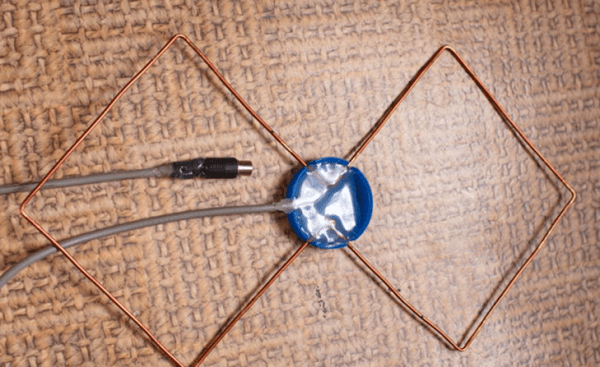
Receiver for digital television
This section is for people who do not wish to use a conventional (analogue) product but want a special UHF antenna to be used for the new format. With your own hands, such a receiving device is also assembled elementarily. To do this, we need a square wooden (can be made of plexiglass) frame with a diagonal of 200 mm and a regular RK-75 cable. The option presented to your attention is a zigzag antenna. She has proven herself well when working in the range of digital television reception. Moreover, it can be used in places where there is no direct line of sight to the signal source. If you have a weak broadcast, you can connect an amplifier to it. So, let's get to work. We clean the end of the cable by 20 mm. Next, we bend the wire in the shape of a square with a diagonal of 175 mm. We bend the end outward at an angle of 45 degrees, the second stripped end is bent to it. We connect the screens tightly. The cleaned central vein hangs freely in the air. At the opposite corner of the square, carefully remove the insulation and the screen in a 200 mm section. This will be the top of our antenna. Now we connect the resulting square with a wooden frame. At the bottom, where the two ends are connected, copper staples made of thick wire should be used. This will provide the best electrical contact. That's all, the decimeter antenna for digital television is ready. If it will be installed outside, you can make a plastic case for it, which will protect the device from precipitation.
Despite the huge number of television antennas on the consumer market, which can be easily purchased at any electronics store, interest in how to make a do-it-yourself TV antenna does not disappear. Such interest can be explained by the reluctance to spend money on the purchase of an antenna, being away from retail outlets (if you are in the outback or in the country) or the failure of the purchased one.
Antennas for a television receiver can be divided into several types.
- All Wave Antenna- the design is easy to manufacture, can be made from simple improvised materials. It picks up a digital signal quite well outside the city, where there is not much interference. When located near a broadcast tower, it can receive analog television.
- Log-periodic band antenna also easy to make. It has perfect coordination with the feeder in all ranges, without changing the parameters in it. Since this design has average technical parameters, it can be used in the country, or as an indoor antenna in the city.
- decimeter antenna. A simplified modification of the Z-antenna is often used, it works well, regardless of the signal reception conditions.
All Wave Antenna
All-wave TV signal catchers are also called frequency-independent (CNA). Their designs may be different.
From two petals
The figure shows an all-wave antenna made of two metal plates triangular shape and two wooden slats, on which copper wire is stretched in the form of a fan.
Copper wire can be taken of any diameter, it does not play a special role. The ends of the wire are fastened at a distance of 20 to 30 mm between each other. Plates with the other ends of the wire soldered together should be located at a distance of 10 mm from each other.
The metal plate can be replaced with a square piece of fiberglass, which has copper foil on one side.
Since the design of a homemade antenna has a square shape, its height will be equal to the width, and the angle between the canvases will be 90 degrees. Zero potential point marked in yellow in the figure. Soldering the cable braid in this place is not required - a tight tie will be enough.
The television signal receiver assembled in this way in the form of two petals is capable of receiving both all decimeter channels and meter channels. Moreover, it catches the signal well in all directions. But if you install the CNA in the zone of poor signal reception from the TV tower, it will only work normally with amplifier. Others can be applied as well.
In the shape of a butterfly
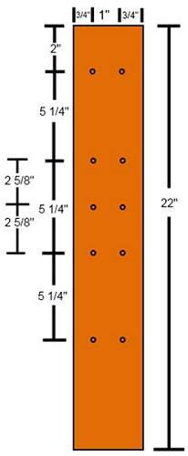
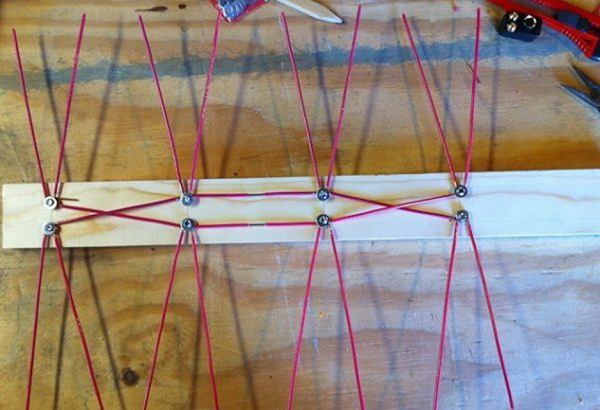
Do-it-yourself TV antenna can be made in the shape of a butterfly. To make this fairly powerful antenna yourself, you need to prepare a board or plywood with dimensions of 550 x 70 x 5 mm, a wire with a copper core section of 4 mm, and, accordingly, a PK75 cable.
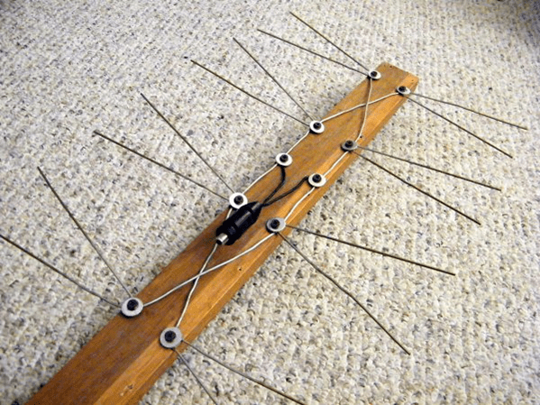
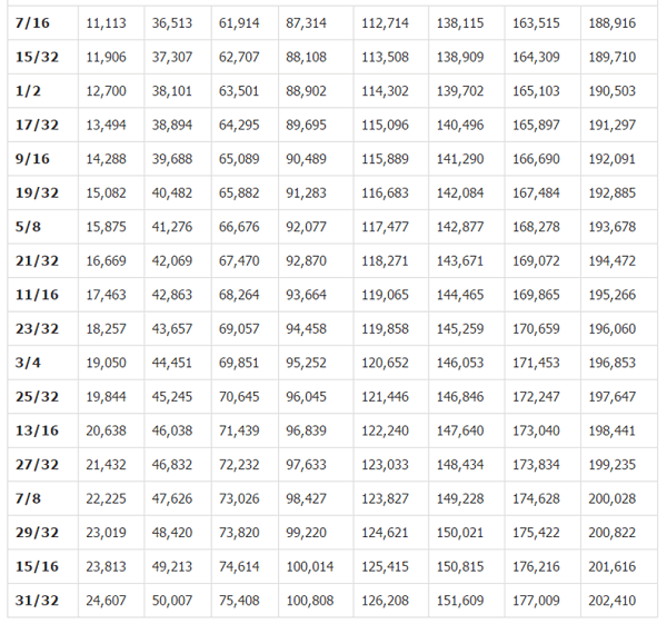
- Mark the holes on the plywood and drill them. The dimensions in the picture are in inches. Below the figure is a table for converting inches to mm.

- From copper wire, it is necessary to cut 8 pieces of the same length of 37.5 cm.
- In the center of each wire, strip the insulation from the sections (2 cm each), as in the figure.
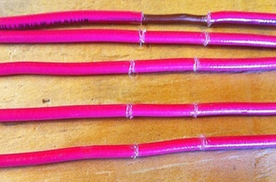
- After that, you should cut off 2 more pieces of wire, already 22 centimeters each, divide them into 3 equal parts and remove the insulation at the separation points.
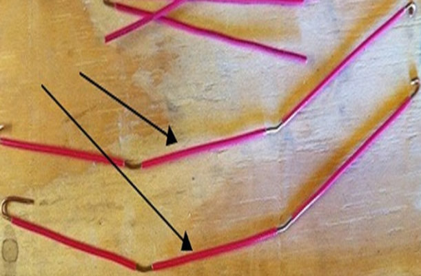
- Attach segments V-shape. You should be careful to maintain a distance of 7.5 cm between the ends of the wire. It is this that is optimal in order to receive a clear signal.

- Connect all the elements according to the figure below.
- Next, you need to purchase a socket for connecting a plug to it.
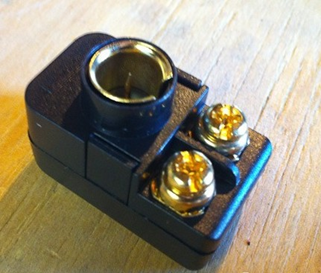
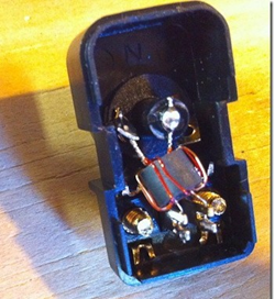
- The cable must be soldered to the coil contacts, as in the figure.
- Make 2 more pieces of wire of the required length to connect the "antennae" to the socket.
- Screw the socket onto the plank and connect all the elements.


That's all - you made an antenna for the TV with your own hands.
From beer cans
To make such an original CHNA, you will need 2 cans (0.5 l or 0.75) of beer or another drink. But before you make a television antenna, you need to consider some material requirements. Namely, it is recommended to purchase a high-quality television cable with a resistance of 1 meter 75 ohms. How right? Pay attention to the fact that the central core is strong, and the braid is double and solid.
Do not forget, the longer the cable is, the stronger the signal damping will be, which is especially important for receiving meter waves, unlike UHF, for which the length of the wire also matters, but not so much.
It will also be necessary to prepare the usual wooden trempel, a couple of self-tapping screws, electrical tape or adhesive tape and, if possible, a soldering iron with tin.
Antenna from beer cans can receive both decimeter and meter wavelengths.
For clarity of the whole process, you can watch the video.
log-periodic antenna
A log-periodic antenna (LPA) can be used to receive radio waves in both the meter and decimeter ranges. To make such a signal receiver, you can use an aluminum tube with a diameter of 10 mm and metal rods (studs), which can be bought at a store that sells fasteners, as a stand. Ideally, instead of threaded rods, it is better to use smooth tubes or rods. A plastic U-shaped box is taken as the basis.
When the soldering is completed, the manufacture of the device can be considered complete and you can start testing your creation.
decimeter antenna
Homemade decimeter signal catchers can have a variety of shapes and designs, from the simplest to manufacture to more complex devices.
annular
The simplest design for receiving UHF can be done in a short time with your own hands from improvised materials. All you need is a coaxial cable and a piece of plywood of the right size.
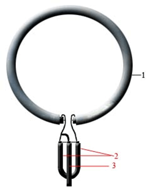
Now all this needs to be collected:
- prepare a piece of coaxial cable (PK75) 530 mm long (a ring will be made from it);
- also cut another piece of cable 175 mm long - this will be a loop;
- make a ring (1), solder a loop (2) to it and a cable (3) that connects to the TV;
- fix it all on a plywood sheet and direct the TV signal receiver made towards the TV tower.
If your TV receiver is using such an antenna, try making a more complex device.
in the shape of a figure eight
A do-it-yourself home UHF antenna can be made from wire in the form of the number 8. To make such a receiver, you can use copper or aluminum wire with a diameter of 3 to 5 mm, as well as a PK75 cable. During the manufacturing process, you will also need glue gun.

Manufacturing progress.
- Using wire cutters, cut 2 pieces of wire 56 cm each.
- At the ends of each segment, make a loop, which should take 1 cm.
- Bend the wire squares and connect the loops. Solder the cable to the squares as shown. The central core is soldered to one square, and the braid to the other. The distance between the elements should be 2 cm. The entire structure can be fixed in the cap from under the 20 liter water bottle, filled with glue.

Such a UHF receiver can be placed anywhere, and it does not require an amplifier. Unless, an amplifier may be needed if the device is outdoor, and the cable length is significant. In this case, to compensate for signal loss, you will need to install it.
From a metal-plastic pipe
A do-it-yourself television antenna can also be made from an ordinary metal-plastic pipe. This will result in a device for receiving UHF with a possible range from 480 MHz to 1000 MHz. This “model” uses a pipe with a diameter of 16 mm and a cable - 5.5 m. The ring will require 55 cm of pipe, and the rack - 14 cm, which is equal to a quarter of a wavelength. This serves to better match the outer sheath of the cable and reduces high frequency currents.

The cable outlet in this design is made through a hole in the pipe. The cable braid should be attached with a clamp to the stripped part of the pipe. The central core of the cable is attached to the ring (you can use a screw with a washer and nut). Such a homemade product works well as a room antenna in apartments with reinforced concrete walls that do not transmit the television wave well. Thanks to the extended cable, you can take it out to the balcony or put it on the windowsill - the reception quality will only improve.
framed
Another design of the UHF antenna is assembled in the form of a frame. It will be made from aluminum plates(bands).
Thus, do-it-yourself antennas will help you save money on their purchase, and in some cases get out of the situation when there is a TV, but the standard antenna is out of order, or it is not there at all. Moreover, the quality of receiving homemade products is not worse than factory counterparts. If you do not want to make the device yourself, then you will need information about that in the store.
Bread and circuses - so said the Roman poet - satirist Juvenal, and in some ways, he was absolutely right. Modern society, and in particular the current person, can no longer do without pretentious pictures, shocking videos, exciting movies, comedy scenes. One of these “elements” that can provide us with access to the world of spectacle is television. But even here it is not enough to have a TV, it is necessary that it also has an antenna. After all, without flourishing antennas, radio waves are also difficult to catch, like a fish on a hook without a bait. What an antenna is for, it’s not something prosaic to say, especially since we have already mentioned it utilitarian, but more disrespectful to our reader. So, skipping the description of the purpose of the antenna, let's proceed to the description of its creation. It is about how to make an antenna with your own hands that we wanted to tell in this article.
Next, one of the simplest and, importantly, affordable ways to make an indoor antenna for your TV will be given. It is made utilitarian out of nothing, or rather - 2 beer cans, self-tapping screws, dress hangers, wire and plug.
Do-it-yourself TV antenna from beer cans
So, we need a couple of beer cans, a soldering iron, a TV cable, solder and something else. About this in the course of our story.

Here it is up to you to know in what sequence and what to do in order to get the much-desired television antenna. If we talk about the requirements for the materials used to make the antenna, then first of all, buy a good TV cable. A good TV cable has a resistance of 75 ohms per meter, a strong center core, and a tight solid double shield. How much cable to buy depends on the location of the antenna, but be aware that the longer the cable, the more "useful" signal will be damped in it. (the rule clearly works for MV shafts). For DMV, it also works, but not so critical.

So, we make a cut for the plug and install it on the wire.

The plugs are now such that they don’t even ask for soldering, so everything will depend on the accuracy of your cuts and the size (diameter) of the cable. The photo is not a very good option for installing the plug on the cable going to the antenna, try to do it better. In principle, you can learn a lot about installing a plug on a TV cable from the article "How to insert a plug on a cable to connect to a TV."

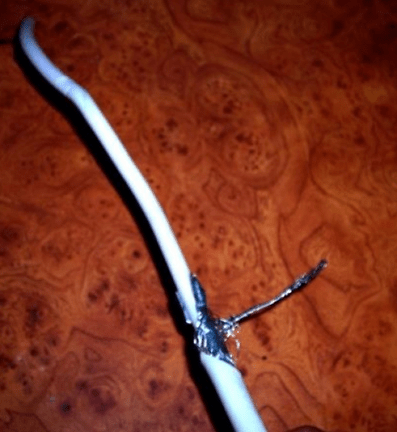
Next, let's start working on the second TV cable cover. Here it is necessary to bring out 2 conductors of the cable one from the very edge, and the second after about 10-15 cm. The first conductor is revered for the core, the second for shielding. Care will also be needed here so as not to cut through excessive layers of insulation and conductors. As a result, the efficiency of the antenna and the clarity of reception of television channels will depend on the quality of each and the total of all works - remember this. In the photo below, you can see how the first and second conductors are removed from the cable. The upper insulation is dropped to a distance of 10-15 cm from the edge of the cable.

Now about beer cans. We do not know what kind of beer you can afford and like, but you need more cans. Again, not many, but large. 0.75 is good, but liter is even better. It's hard to say anything about the big 5 l kegs of beer. This will probably go beyond the "framework" of the indoor antenna. After drinking beer, rinse the jars in water and dry them so that they do not measure the aroma of the intoxicating drink. Such a smell of a radio wave will not attract waves, but flies for sure.
Now we take the cable that we prepared earlier. With small screws, we fasten one conductor to the end of the first can, the other to the end of the second. Use solder to improve contact between the body of the can and the self-tapping screw. Fill in all likely gaps to improve contact.

Now our antenna is almost ready, there is not enough frame in order to base the banks among themselves and for what to fix the antenna to something. In our case, the hangers for the dress acted as a frame. For this there are all criteria "FOR". Low price, availability, proper rigidity and dimensions. Yes, and a hook to hang everything at once in the chosen place.
So, we place the banks on one even, so that they are symmetrical about the center. Play a little with the distance between them, as the quality of signal reception will depend on this. You can secure the jars with tape or tape. The exemplary distance for cans on the antenna is about 75 mm.

As a result, we get not a crafty, but a functional thing - an indoor television antenna from beer cans. Of course, such an antenna is capable of operating only in the zone of confident enrollment of a television signal. This is not an antenna for receiving a signal 20 km from the city, this is just something that will slightly make the reception more confident, but not ideal.
Professionals, perhaps, are already maliciously laughing at this article and the antenna, because in fact a television antenna requires a harsh and accurate calculation of its elements, depending on the received wavelength. In this they are absolutely right. But this calculation is not always available to the average layman, which prompts him to such adventures in the manufacture of antennas, as in particular for the antenna given here, from beer cans.
Next, we will consider a more serious option. First of all, its big plus is that it will talk about how to make an antenna in accordance with all the rules, taking into account the physiological characteristics of the propagation of radio waves.
Radio waves received by a TV antenna
 Since we have climbed so far, it is necessary to at least say about the basics, because how could it be otherwise !? The radio waves of television channels of the analog signal propagate in the range of meter (MV) and decimeter shafts (UHF).
In fact, this is the same thing, except that the MW and UHF waves propagate with different frequencies of the radio wave. Meter shafts are from channels 1 to 21, and UHF from channels 21 to 40. It is important to note here that, depending on the wavelength, it will be necessary to use an appropriate antenna for MV or UHF shafts. It is also necessary to say that antennas are both indoor and outdoor. Let's consider one and the other option.
Do-it-yourself indoor antennas for TV (MV and UHF)
MV indoor antenna
The force of magnetic waves in the room is much less than outside. Therefore, it makes sense to use indoor antennas only in the immediate vicinity of the television center. So the simplest indoor antenna can be made from an electrical wire, or any other insulated conductor. An insulator is installed in the center of the antenna. Two guides are attached to it by means of fasteners (bolt - nut). The ends of the conductors are stretched so that they are even, like strings or rods.

The total length of the conductors, two antenna frames, is taken according to the wavelength and the received channel. These these can be taken from the table.
If you choose the length of the antenna guides, according to the television channel you are watching, then it will be much more effective than beer cans.
Next, we will give another version of the indoor antenna for the TV, which you can do yourself. This is a UHF antenna. Despite the fact that UHF channels are practically not used, nevertheless, broadcasting is still sometimes carried out somewhere. So, we also cannot avoid this topic. Here is an example of a UHF antenna.
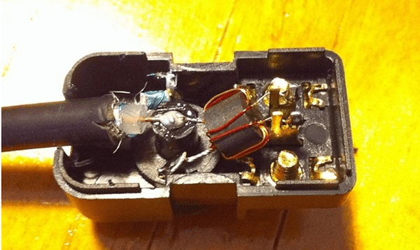
UHF indoor antenna

The applied mounting wire, referred to as KPTA-1, serves to increase the noise immunity of the antenna. For this, as you can see, at a distance of 140 mm from the edge of the cable, the insulation was stripped to the screen and this mounting wire was soldered - a loop. You can use a different wire with a cross section of 0.35 mm.
The frequency of the received radio waves of this antenna will be from 470 to 630 MHz, that is, UHF waves.
All elements of the antenna are mounted on a stand, which is a dielectric.
Do-it-yourself street antennas for TV (MV)
Antenna - half-wave linear vibrator
This outdoor antenna is designed to receive television waves near the city 20-30 km. In fact, this is an analogue of the simplest indoor antenna, which we already talked about a little earlier, except that it is adapted for the street.
So, as we have already comprehended, the antenna must have certain dimensions that will affect the enrollment of television radio waves. The dimensions will depend on which channel you are going to watch. All dimensions for the antenna can be found in the table.
Rice. 1. Antenna - half-wave linear vibrator (Imagine a simple television antenna)
The input impedance of the linear vibrator (antenna) is equal to 73 ohms. The bandwidth of a linear vibrator depends on the outer diameter of its tubes and grows with an increase in the final one.
You should not choose D greater than 30 mm, since with its further increase, the image quality does not noticeably improve, and the weight and dimensions of the antenna increase.
In table. 1 shows the dimensions of the elements of a linear vibrator. Gap A between the ends of the tubes is equal to 50-70 mm.

The antenna is connected to a TV with an unbalanced 75-ohm input using a coaxial cable (RK-75-4-15, RK-75-9-12, etc.) The cable is connected to the antenna through a special balancing device (see Fig. 2 ).

The required dimensions of the elements of the matching structures are selected according to the table. 2.

The antenna is made from steel, aluminum or brass tubes and metal strips. To attach the antenna tubes to a metal or wooden mast, porcelain insulators and textolite are used.
Antenna - a half-wave vibrator is used in conditions of short-range enrollment, this has already been discussed. (20-30 km). This version of the antenna, of course, is much more laborious than an indoor antenna, but its efficiency will be much higher. To enroll television programs far from the city, or rather from the transmitter, a "wave channel" antenna is used.
Antenna "wave channel" MV and UHF do-it-yourself calculation and scheme
At large distances from the transmitter, that is, the television center, this is the order of 40-90 km, antennas of the "wave channel" type are used. These antennas have a very good gain, but require strict directivity. If you use such an antenna in populated areas, then this will reduce interference from adjacent sources, thereby improving the image image.
Antenna "wave channel" in its structure consists of an active loop and linear vibrator. We talked about the linear vibrator in the previous paragraphs. The size of the antenna is selected based on the considerations of signal amplification, the farther, the more complex the antenna will be. Also, the number of directors can improve the receiving properties of the antenna by changing its sensitivity to the direction to the transmitter.
however, a large increase in the number of directors leads to a decrease in bandwidth. Here it is necessary to find the "golden mean". So on the channels of the MW range, 3, 5 and 7 element antennas are used.

The geometric dimensions of such antennas of the "wave channel" image are given in the table. At the same time, for channels 1-5, 18 mm tubes are used in the design, and for channels 6-12, 12 mm.
| TV channel number | Dimensions in mm, for a three-element wave channel antenna | |||||
| BUT | B | AT | a | b | in | |
| 1 | 2710 | 3040 | 2360 | 880 | 595 | 800 |
| 2 | 2300 | 2580 | 2000 | 750 | 505 | 800 |
| 3 | 1780 | 2000 | 1550 | 580 | 390 | 800 |
| 4 | 1620 | 1820 | 1410 | 530 | 355 | 800 |
| 5 | 1480 | 1660 | 1290 | 480 | 325 | 800 |
| 6 | 795 | 900 | 695 | 260 | 175 | 550 |
| 7 | 165 | 860 | 665 | 250 | 170 | 550 |
| 8 | 735 | 825 | 640 | 240 | 165 | 550 |
| 9 | 705 | 795 | 615 | 230 | 155 | 550 |
| 10 | 680 | 765 | 590 | 225 | 150 | 550 |
| 11 | 650 | 730 | 570 | 220 | 145 | 550 |
| 12 | 630 | 705 | 550 | 205 | 140 | 550 |
| TV channel number | Dimensions in mm, for a five-element wave channel antenna | |||||||||
| BUT | B | AT | G | D | a | b | in | G | d | |
| 1 | 2780 | 3150 | 2520 | 2510 | 2450 | 1210 | 735 | 705 | 750 | 800 |
| 2 | 2350 | 2660 | 2135 | 2125 | 2070 | 1040 | 625 | 595 | 630 | 800 |
| 3 | 1800 | 2035 | 1630 | 1620 | 1580 | 780 | 475 | 480 | 480 | 800 |
| 4 | 1620 | 1830 | 1470 | 1460 | 1420 | 700 | 425 | 430 | 430 | 800 |
| 5 | 1490 | 1680 | 1350 | 1340 | 1300 | 645 | 390 | 395 | 395 | 800 |
| 6 | 810 | 915 | 730 | 725 | 710 | 350 | 215 | 215 | 215 | 550 |
| 7 | 780 | 880 | 705 | 700 | 680 | 340 | 205 | 205 | 205 | 550 |
| 8 | 740 | 840 | 670 | 665 | 650 | 325 | 195 | 195 | 195 | 550 |
| 9 | 715 | 810 | 650 | 645 | 625 | 310 | 190 | 190 | 190 | 550 |
| 10 | 690 | 780 | 625 | 620 | 600 | 295 | 180 | 180 | 180 | 550 |
| 11 | 660 | 750 | 60 | 595 | 585 | 285 | 175 | 175 | 175 | 550 |
| 12 | 635 | 720 | 575 | 570 | 550 | 270 | 170 | 170 | 170 | 550 |
| TV channel number | Dimensions in mm, for seven-element wave channel antenna | ||||||||||||
| BUT | B | AT | G | D | E | AND | a | b | G | d | e | and | |
| 1 | 2760 | 3220 | 2200 | 2180 | 2160 | 2130 | 2105 | 1180 | 415 | 845 | 870 | 905 | 800 |
| 2 | 2340 | 2730 | 1870 | 1850 | 1830 | 1810 | 1790 | 910 | 350 | 715 | 735 | 765 | 800 |
| 3 | 1810 | 2120 | 1450 | 1430 | 1415 | 1400 | 1380 | 710 | 275 | 560 | 570 | 595 | 800 |
| 4 | 1650 | 1920 | 1320 | 1300 | 1290 | 1270 | 1260 | 645 | 250 | 505 | 520 | 540 | 800 |
| 5 | 1510 | 1760 | 1200 | 1190 | 1180 | 1160 | 1150 | 590 | 225 | 460 | 475 | 495 | 800 |
| 6 | 710 | 925 | 700 | 655 | 620 | 565 | 520 | 310 | 125 | 385 | 400 | 425 | 550 |
| 7 | 680 | 885 | 670 | 625 | 595 | 540 | 500 | 295 | 120 | 370 | 385 | 405 | 550 |
| 8 | 650 | 850 | 640 | 600 | 570 | 520 | 480 | 285 | 115 | 355 | 370 | 390 | 550 |
| 9 | 625 | 815 | 620 | 575 | 545 | 500 | 460 | 275 | 110 | 340 | 350 | 375 | 550 |
| 10 | 600 | 785 | 595 | 555 | 525 | 480 | 440 | 265 | 105 | 325 | 330 | 360 | 550 |
| 11 | 580 | 755 | 570 | 535 | 505 | 460 | 425 | 255 | 100 | 315 | 325 | 345 | 550 |
| 12 | 560 | 730 | 555 | 515 | 485 | 445 | 410 | 245 | 95 | 305 | 320 | 335 | 550 |
But for UHF shafts, a 16-element antenna is used. The diameter of the tubes is 6-10 mm, and for the arrow 14-16 mm.

For her, the dimensions are also shown in the table.
| TV channel number | Dimensions in mm, for 11-element antenna "wave channel" UHF | ||||
| 21-25 | 26-30 | 31-35 | 36-40 | 21-40 | |
| BUT B AT G D E AND Z And To L a b in G d e and h and to l | 308 377 293 290 287 283 279 276 272 269 265 140 72 92 104 121 132 133 134 136 137 240 | 284 348 270 267 264 260 257 254 251 248 245 129 67 85 96 112 122 123 124 126 127 240 | 264 324 252 249 246 243 240 237 234 231 228 120 62 79 89 104 113 114 115 117 118 240 | 247 303 235 232 229 226 223 220 217 214 210 112 58 74 83 97 105 106 107 109 110 240 | 274 336 261 258 255 252 249 246 243 240 237 125 64 82 92 104 117 118 119 121 122 240 |
After the antenna is ready, it will be necessary to stretch the television, antenna cable from it to the TV. About this in the article "Connecting a TV to an antenna cable through a plug."
 Lighting in the country or at home
  Which lamps are better for home LED or energy saving
  Is it possible to stretch a television cable along with an electric
  How to connect GS E501/GS C591 Tricolor TV receivers to each other and to a satellite dish
  Commands to enable and disable options for mobile operators (MTS, Beeline, Megafon)
Dear readers of the NskTarelka.ru blog, if you are interested in the answer to the question - Which antenna to choose for digital terrestrial TV? Well, this article is just for you.
Before we start talking about choosing a television antenna for DVB-T2 digital television, let's talk a little about terrestrial television itself.
Terrestrial television - broadcasting formats, signal broadcasting
Television free channels, which we watch by receiving a signal on indoor or outdoor (street) antennas, are the same terrestrial television. The television (radio) signal is broadcast from the repeater to the air, that is, to the surrounding space, by means of electromagnetic waves. We, as users, using terrestrial antennas, receive this television signal.
To transmit a television signal, meter MV (VHF) and decimeter UHF (UHF) waves are used.
Digital terrestrial television of the DVB-T2 standard is broadcast on the air via UHF decimeter waves (UHF). Accordingly, in order to watch the "figure" you need to have the "correct" antenna. It must be either all-wave (MV (VHF) + UHF (UHF)), or UHF decimeter range (UHF). With an antenna receiving only MV (VHF), the range of viewing digital terrestrial television will not be possible.
MV and UHF are the ultra-short wave (VHF) bands allocated for the transmission of a television signal. Frequency band from 48 to 862 MHz with conditional division into 5 bands combined into two groups:
- 1-12 meter channels or MV (VHF), bands I, II, III (47-160 MHz);
- 21-60 channels decimeter, in a different way UHF (UHF), bands IV, V. (470-862 MHz).
Broadcasting of analog terrestrial television is in both bands, both in MV and UHF. Previously, it was planned to turn off analog TV in Russia until the end of 2015, but now the deadlines have been moved to 2018.
Which antenna to choose for digital TV?
Since we choose an antenna for digital TV, it is understood that we have a DVB-T2 set-top box, or a TV with a built-in DVB-T2 tuner. We have accurate information that in the place we are interested in, where we want to enjoy watching digital television, it is already available.
Not that I am “Captain Obvious” or as if for those who are “in the tank”, but you never know, just in case. Suddenly, one of the readers is not in the know, and thinks that to watch digital television, the “necessary” antenna is enough. No, it's not.
So, before spending money on an antenna, we check what is available. It is quite possible, it is enough to connect to the old antenna and everything will work.
If your antenna previously received channels of analog terrestrial television going in the UHF range, respectively, and digital television, it is quite possible that it will work without problems. It is enough to connect everything and scan the channels.
Why did I write quite possibly? Because there are some nuances. There are such concepts as the difference in altitude between your location and available repeaters that transmit a television signal.
Collective Antenna
First of all, if you live in an apartment building and it uses a collective antenna, try to connect through it. If everything works, great.
If not, contact the organization serving you with a request to deal with the television signal or install your own.
indoor antenna
Whether a room antenna is enough for high-quality digital television reception depends on the remoteness of the repeater (transmitter), as well as its power. The power of the transmitter of interest can be found at the counseling center.
Or, as an option, on the RTRS website, in the upper right corner, click on "Select Region", select your region (republic, region, district). After that, click on "Digital TV" in the menu. On the page that opens, click on the link "Objects of digital broadcasting of the RTRS-1 package". In the table that opens, there will be information about the power of the transmitters.
On average, the radius of the coverage area of a DVB-T2 digital transmitter in the decimeter range, under the most ideal conditions (the height of the receiving antenna is 10 m, flat terrain, line of sight):
- 10 W - about 3 km.
- 50 W - about 5 km.
-100 W - about 15 km.
- 500 W - about 25 km.
-1 kW - about 30-35 km.
- 2 kW - about 35-40 km.
- 5 kW - about 40 - 50 km.
RTRS group VKontakte
When the TV tower is in direct line of sight from the window, even reception without an antenna is possible. It is enough to connect a piece of coaxial cable, popularly called antenna.
When connecting one TV, choosing between the options of a passive antenna or an active one, we give preference to a passive one. Passive is the one without an amplifier. Active with amplifier.
To broadcast the DVB-T2 standard to several TVs, an active antenna is purchased. Since the signal is diluted with a divider to two or more TVs, losses occur that are compensated by the amplifier. If there is a choice, an antenna with adjustable signal gain is purchased. Thanks to this, we can control the signal amplification power.
The proposed choice of indoor antennas can give you a headache. Which one to buy?
The upper price range is usually not good. Many expensive ones are not good at all.
No need to focus on those promoted as specialized for DVB-T2. Often this is beautiful trash for big money. There are no specialized DVB-T2 antennas - this is a marketing ploy.
As I said above, the television signal broadcasts at the frequencies of the meter - MV (VHF), and decimeter UHF (UHF) VHF bands. To date, the UHF range has been allocated to the DVB-T2 digital terrestrial television standard. And the UHF band antenna will be correct, and not the DVB-T2 antenna.
Therefore, if a super-duper for DVB-T2 is written on the box, this does not mean anything.
If the TV tower is not visible from your window, but it is relatively close, it is advisable to purchase a directional indoor antenna. The signal in this case comes to you reflected from other houses - a directional indoor antenna is the best option here.
In terms of price and quality ratio, an excellent option would be to purchase one of the brands - LOCUS (Locus) Moscow or Delta St. Petersburg.
If possible, before buying an indoor antenna, try to borrow it to test the signal from friends. Or if you buy in a specialized store, you may be able to agree on a return with a replacement for a street one.
Outdoor (street) antenna
When it’s impossible to catch a room antenna or, due to the distance, it doesn’t even make sense to try, we use an outdoor (street) antenna. If there is an old one that is already on the roof or on the balcony, or outside the window, first we try to catch it. No antenna, let's go to the store.
What should be guided by when choosing an outdoor (street) antenna? To begin with, using the DVB-T2 digital television coverage area map, we determine the distance from the antenna installation site, to the repeater from which we plan to catch the signal.
When choosing an antenna, we take into account the signal strength of the repeater. The power of the tower determines its reception area.
If the terrain is not flat, it makes sense to find out the height difference between your location and the available repeaters transmitting a television signal.
When connecting one TV, as in the case of an indoor antenna, choosing a passive outdoor antenna is preferable to choosing an active one.
When wiring a signal to two or more TVs, we use an active antenna, that is, with an amplifier. If possible, we purchase it with adjustable gain.
When buying, we prefer an antenna made only for the decimeter range - UHF (UHF). If you plan to watch analog channels in parallel with digital ones, until they are turned off, purchase an all-wave channel that supports both ranges. And meter - MV (VHF), and decimeter UHF (UHF).
In addition to the moment of choosing the parameters of the antenna, remember the equally important thing to consider during installation. It is about the height of the installed antenna. There are cases, and they are far from isolated, when the most powerful antenna for receiving a signal will not help either. But it is enough to raise the antenna a couple of meters in height, and it turns out that the old, less powerful one would be enough.
International standards for the zone of reliable reception of television broadcasting are published based on the calculation of the height of the antenna suspension:
For rural areas at least 10 m
- suburb, not less than 20 m
- city 30 m
Therefore, the best solution for hanging the antenna is the highest point, i.e. the roof.
And at the end of the article, I bring to your attention a video from RTRS - How to set up an antenna for receiving digital terrestrial TV. Possible problems and ways to solve them.
In contact with


