A transformer that increases voltage and frequency many times is called a Tesla transformer. Energy-saving and fluorescent lamps, picture tubes of old TVs, charging batteries from a distance and much more were created thanks to the operating principle of this device. Let’s not exclude its use for entertainment purposes, because the “Tesla transformer” is capable of creating beautiful purple discharges - streamers reminiscent of lightning (Fig. 1). During operation, an electromagnetic field is formed that can affect electronic devices and even the human body, and during discharges in the air a chemical process occurs with the release of ozone. To make a Tesla transformer with your own hands, you do not need to have extensive knowledge in the field of electronics, just follow this article.
Components and operating principle
All Tesla transformers, due to a similar operating principle, consist of identical blocks:
- Power supply.
- Primary circuit.

The power supply provides the primary circuit with voltage of the required magnitude and type. The primary circuit creates high-frequency oscillations that generate resonant oscillations in the secondary circuit. As a result, a current of high voltage and frequency is formed on the secondary winding, which tends to create an electrical circuit through the air - a streamer is formed.
The choice of primary circuit determines the type of Tesla coil, power source and size of the streamer. Let's focus on the semiconductor type. It features a simple circuit with accessible parts and a low supply voltage.
Selection of materials and parts
We will search and select parts for each of the above structural units:


After winding, we insulate the secondary coil with paint, varnish or other dielectric. This will prevent the streamer from getting into it.
Terminal – additional capacity of the secondary circuit, connected in series. For small streamers it is not necessary. It is enough to bring the end of the coil up 0.5–5 cm.
After we have collected all the necessary parts for the Tesla coil, we begin to assemble the structure with our own hands.
Design and assembly
We carry out the assembly according to the simplest scheme in Figure 4.

We install the power supply separately. The parts can be assembled by hanging installation, the main thing is to avoid short circuits between the contacts.
When connecting a transistor, it is important not to mix up the contacts (Fig. 5).

To do this, we check the diagram. We tightly screw the radiator to the transistor body.
Assemble the circuit on a dielectric substrate: a piece of plywood, a plastic tray, a wooden box, etc. Separate the circuit from the coils with a dielectric plate or board with a miniature hole for the wires.
We secure the primary winding so as to prevent it from falling and touching the secondary winding. In the center of the primary winding we leave space for the secondary coil, taking into account the fact that the optimal distance between them is 1 cm. It is not necessary to use a frame - a reliable fastening is enough.
We install and secure the secondary winding. We make the necessary connections according to the diagram. You can see the operation of the manufactured Tesla transformer in the video below.
Switching on, checking and adjusting
Before turning on, move electronic devices away from the test site to prevent damage. Remember electrical safety! To launch successfully, perform the following steps in order:
- We set the variable resistor to the middle position. When applying power, make sure there is no damage.
- Visually check the presence of the streamer. If it is missing, we bring a fluorescent light bulb or incandescent lamp to the secondary coil. The glow of the lamp confirms the functionality of the “Tesla transformer” and the presence of an electromagnetic field.
- If the device does not work, first of all we swap the leads of the primary coil, and only then we check the transistor for breakdown.
- When you turn it on for the first time, monitor the temperature of the transistor; if necessary, connect additional cooling.
Distinctive features of the powerful Tesla transformer are high voltage, large dimensions of the device and the method of producing resonant oscillations. Let's talk a little about how it works and how to make a Tesla spark-type transformer.
The primary circuit operates on alternating voltage. When turned on, the capacitor charges. As soon as the capacitor is charged to the maximum, a breakdown of the spark gap occurs - a device of two conductors with a spark gap filled with air or gas. After the breakdown, a series circuit of a capacitor and a primary coil is formed, called an LC circuit. It is this circuit that creates high-frequency oscillations, which create resonant oscillations and enormous voltage in the secondary circuit (Fig. 6).

If you have the necessary parts, you can assemble a powerful Tesla transformer with your own hands, even at home. To do this, it is enough to make changes to the low-power circuit:
- Increase the diameters of the coils and the cross-section of the wire by 1.1 - 2.5 times.
- Add a toroid-shaped terminal.
- Change the DC voltage source to an alternating one with a high boost factor that produces a voltage of 3–5 kV.
- Change the primary circuit according to the diagram in Figure 6.
- Add reliable grounding.
Tesla spark transformers can reach a power of up to 4.5 kW, therefore creating large-sized streamers. The best effect is obtained when the frequencies of both circuits are equal. This can be realized by calculating parts in special programs - vsTesla, inca and others. You can download one of the Russian-language programs from the link: http://ntesla.at.ua/_fr/1/6977608.zip.

A Tesla coil is a high-frequency resonant transformer without a ferromagnetic core, which can be used to obtain high voltage on the secondary winding. Under the influence of high voltage in the air, an electrical breakdown occurs, similar to a lightning strike. The device was invented by Nikola Tesla, and bears his name.
According to the type of switching element of the primary circuit, Tesla coils are divided into spark (SGTC - Spark gap Tesla coil), transistor (SSTC - Solid state Tesla coil, DRSSTC - Dual resonant solid state Tesla coil). I will only consider spark coils, which are the simplest and most common. According to the method of charging the loop capacitor, spark coils are divided into 2 types: ACSGTC - Spark gap Tesla coil, and DCSGTC - Spark gap Tesla coil. In the first option, the capacitor is charged with an alternating voltage; in the second, a resonant charge is used with a constant voltage applied.

The coil itself is a structure of two windings and a torus. The secondary winding is cylindrical, wound on a dielectric pipe with copper winding wire, in one layer turn to turn, and usually has 500-1500 turns. The optimal ratio of the diameter and length of the winding is 1:3.5 – 1:6. To increase electrical and mechanical strength, the winding is coated with epoxy glue or polyurethane varnish. Typically, the dimensions of the secondary winding are determined based on the power of the power source, that is, the high-voltage transformer. Having determined the diameter of the winding, the length is found from the optimal ratio. Next, select the diameter of the winding wire so that the number of turns is approximately equal to the generally accepted value. Sewer plastic pipes are usually used as a dielectric pipe, but you can also make a homemade pipe using sheets of drawing paper and epoxy glue. Hereinafter we are talking about medium coils, with a power of 1 kW and a secondary winding diameter of 10 cm.
A hollow conductive torus, usually made of corrugated aluminum pipe, is installed at the upper end of the secondary winding pipe to remove hot gases. Basically, the diameter of the pipe is selected equal to the diameter of the secondary winding. The diameter of the torus is usually 0.5-0.9 times the length of the secondary winding. The torus has an electrical capacitance, which is determined by its geometric dimensions, and acts as a capacitor.
The primary winding is located at the lower base of the secondary winding, and has a spiral flat or conical shape. Typically consists of 5-20 turns of thick copper or aluminum wire. High-frequency currents flow in the winding, as a result of which the skin effect can have a significant influence. Due to the high frequency, the current is distributed predominantly in the surface layer of the conductor, thereby reducing the effective cross-sectional area of the conductor, which leads to an increase in active resistance and a decrease in the amplitude of electromagnetic oscillations. Therefore, the best option for making the primary winding would be a hollow copper tube or a flat wide strip. An open protective ring (Strike Ring) from the same conductor is sometimes installed above the primary winding along the outer diameter and grounded. The ring is designed to prevent discharges from entering the primary winding. The gap is necessary to prevent current flow through the ring, otherwise the magnetic field created by the induction current will weaken the magnetic field of the primary and secondary windings. The protective ring can be dispensed with by grounding one end of the primary winding, and the discharge will not harm the coil components.
The coupling coefficient between the windings depends on their relative position; the closer they are, the greater the coefficient. For spark coils, a typical coefficient value is K=0.1-0.3. The voltage on the secondary winding depends on it; the higher the coupling coefficient, the higher the voltage. But it is not recommended to increase the coupling coefficient above the norm, since discharges will begin to jump between the windings, damaging the secondary winding. 
The diagram shows the simplest version of a Tesla coil of the ACSGTC type.
The operating principle of a Tesla coil is based on the phenomenon of resonance of two inductively coupled oscillatory circuits. The primary oscillatory circuit consists of a capacitor C1, a primary winding L1, and is switched by a spark gap, resulting in a closed circuit. The secondary oscillatory circuit is formed by the secondary winding L2 and capacitor C2 (a toroid with capacitance), the lower end of the winding must be grounded. When the natural frequency of the primary oscillatory circuit coincides with the frequency of the secondary oscillatory circuit, a sharp increase in the amplitude of voltage and current in the secondary circuit occurs. At a sufficiently high voltage, electrical breakdown of the air occurs in the form of a discharge emanating from the torus. It is important to understand what a closed secondary circuit is. The secondary circuit current flows through the secondary winding L2 and capacitor C2 (torus), then through air and ground (since the winding is grounded), the closed circuit can be described as follows: ground-winding-torus-discharge-ground. Thus, the exciting electrical discharges are part of the circuit current. If the grounding resistance is high, the discharges emanating from the torus will hit directly the secondary winding, which is not good, so you need to do high-quality grounding.
Once the dimensions of the secondary winding and torus are determined, the natural frequency of oscillation of the secondary circuit can be calculated. Here we must take into account that the secondary winding, in addition to inductance, has some capacitance due to its considerable size, which must be taken into account when calculating; the winding capacitance must be added to the torus capacitance. Next, you need to estimate the parameters of the coil L1 and capacitor C1 of the primary circuit, so that the natural frequency of the primary circuit is close to the frequency of the secondary circuit. The capacitance of the primary circuit capacitor is usually 25-100 nF, based on this, the number of turns of the primary winding is calculated, on average it should be 5-20 turns. When making a winding, it is necessary to increase the number of turns compared to the calculated value in order to subsequently tune the coil to resonance. All these parameters can be calculated using standard formulas from a physics textbook; there are also books online on calculating the inductance of various coils. There are also special calculator programs for calculating all the parameters of the future Tesla coil.
The adjustment is carried out by changing the inductance of the primary winding, that is, one end of the winding is connected to the circuit, and the other is not connected anywhere. The second contact is made in the form of a clamp, which can be transferred from one turn to another, thereby not the entire winding is used, but only part of it, and the inductance and natural frequency of the primary circuit change accordingly. The tuning is carried out during preliminary launches of the coil; the resonance is judged by the length of the discharged discharges. There is also a method for cold tuning the resonance using an RF generator and an oscilloscope or RF voltmeter, without the need to run the coil. It is necessary to note that the electric discharge has a capacitance, as a result of which the natural frequency of the secondary circuit may decrease slightly during operation of the coil. Grounding may also have a small effect on the secondary frequency.
The spark gap is a switching element in the primary oscillatory circuit. When an electrical breakdown of the spark gap occurs under the influence of high voltage, an arc is formed in it, which closes the circuit of the primary circuit, and high-frequency damped oscillations arise in it, during which the voltage on capacitor C1 gradually decreases. After the arc goes out, the loop capacitor C1 begins to charge again from the power source, and with the next breakdown of the spark gap, a new cycle of oscillations begins.
The arrester is divided into two types: static and rotating. A static discharger consists of two closely spaced electrodes, the distance between which is adjusted so that an electrical breakdown between them occurs at a time when the capacitor C1 is charged to the highest voltage, or slightly less than the maximum. The approximate distance between the electrodes is determined based on the electrical strength of air, which is about 3 kV/mm under standard environmental conditions, and also depends on the shape of the electrodes. For alternating mains voltage, the response frequency of the static discharge (BPS - beats per second) will be 100 Hz.
A rotating spark gap (RSG - Rotary spark gap) is made on the basis of an electric motor, on the shaft of which a disk with electrodes is mounted; static electrodes are installed on each side of the disk, thus, when the disk rotates, all the electrodes of the disk will fly between the static electrodes. The distance between the electrodes is kept to a minimum. In this option, you can adjust the switching frequency over a wide range by controlling the electric motor, which gives more opportunities for tuning and controlling the coil. The motor housing must be grounded to protect the motor winding from breakdown when exposed to a high-voltage discharge.
Capacitor assemblies (MMC - Multi Mini Capacitor) of series and parallel connected high-voltage high-frequency capacitors are used as loop capacitor C1. Typically, ceramic capacitors of the KVI-3 type are used, as well as film capacitors K78-2. Recently, a transition to paper capacitors of the K75-25 type has been planned, which have shown good performance. For reliability, the rated voltage of the capacitor assembly should be 1.5-2 times the amplitude voltage of the power source. To protect capacitors from overvoltage (high-frequency pulses), an air gap is installed parallel to the entire assembly. The spark gap can be two small electrodes.
A high-voltage transformer T1, or several series- or parallel-connected transformers, is used as a power source for charging the capacitors. Basically, novice Tesla builders use a microwave oven transformer (MOT - Microwave Oven Transformer), the output alternating voltage of which is ~2.2 kV, the power is about 800 W. Depending on the rated voltage of the loop capacitor, MOTs are connected in series from 2 to 4 pieces. The use of only one transformer is not advisable, since due to the small output voltage the gap in the spark gap will be very small, resulting in unstable results of the coil operation. The motors have the disadvantages of poor electrical strength, are not designed for long-term operation, and get very hot under heavy loads, so they often fail. It is more reasonable to use special oil transformers such as OM, OMP, OMG, which have an output voltage of 6.3 kV, 10 kV, and a power of 4 kW, 10 kW. You can also make a homemade high-voltage transformer. When working with high-voltage transformers, one should not forget about safety precautions; high voltage is dangerous to life; the transformer housing must be grounded. If necessary, an autotransformer can be installed in series with the primary winding of the transformer to regulate the charging voltage of the loop capacitor. The power of the autotransformer must be no less than the power of transformer T1.
The inductor Ld in the power circuit is necessary to limit the short circuit current of the transformer in the event of breakdown of the spark gap. Most often, the inductor is located in the secondary winding circuit of transformer T1. Due to the high voltage, the required inductance of the inductor can take large values from units to tens of Henry. In this embodiment, it must have sufficient electrical strength. With the same success, the inductor can be installed in series with the primary winding of the transformer; accordingly, high electrical strength is not required here, the required inductance is an order of magnitude lower, and amounts to tens, hundreds of millihenries. The diameter of the winding wire must be no less than the diameter of the wire of the primary winding of the transformer. The inductance of the inductor is calculated from the formula for the dependence of inductive reactance on the frequency of alternating current.
The low-pass filter (LPF) is designed to prevent the penetration of high-frequency pulses of the primary circuit into the inductor circuit and the secondary winding of the transformer, that is, to protect them. The filter can be L-shaped or U-shaped. The cutoff frequency of the filter is chosen to be an order of magnitude lower than the resonant frequency of the oscillatory circuits of the coil, but the cutoff frequency must be much higher than the response frequency of the spark gap. 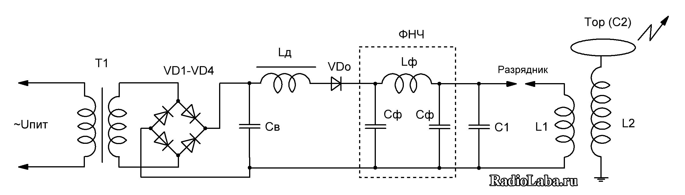
When resonantly charging a loop capacitor (coil type - DCSGTC), a constant voltage is used, unlike ACSGTC. The voltage of the secondary winding of transformer T1 is rectified using a diode bridge and smoothed with capacitor St. The capacitance of the capacitor should be an order of magnitude greater than the capacitance of loop capacitor C1 to reduce DC voltage ripple. The capacitance value is usually 1-5 µF; for reliability, the rated voltage is chosen to be 1.5-2 times the amplitude rectified voltage. Instead of one capacitor, you can use capacitor assemblies, preferably not forgetting about equalizing resistors when connecting several capacitors in series.
High-voltage diode columns of the KTs201 type and others are used in series as bridge diodes. The rated current of the diode columns must be greater than the rated current of the secondary winding of the transformer. The reverse voltage of the diode columns depends on the rectification circuit; for reliability reasons, the reverse voltage of the diodes should be 2 times the amplitude value of the voltage. It is possible to manufacture homemade diode posts by connecting conventional rectifier diodes in series (for example 1N5408, Urev = 1000 V, In = 3 A), using equalizing resistors.
Instead of the standard rectification and smoothing circuit, you can assemble a voltage doubler from two diode columns and two capacitors.
The operating principle of the resonant charge circuit is based on the phenomenon of self-inductance of the inductor Ld, as well as the use of a cut-off diode VDо. At the moment when capacitor C1 is discharged, current begins to flow through the inductor, increasing according to a sinusoidal law, while energy is accumulated in the inductor in the form of a magnetic field, and the capacitor is charged, accumulating energy in the form of an electric field. The voltage across the capacitor increases to the voltage of the power supply, while the maximum current flows through the inductor, and the voltage drop across it is zero. In this case, the current cannot stop instantly, and continues to flow in the same direction due to the presence of self-induction of the inductor. Charging of the capacitor continues until the power source voltage is doubled. A cut-off diode is necessary to prevent energy from flowing from the capacitor back to the power source, since a potential difference appears between the capacitor and the power source equal to the voltage of the power source. In fact, the voltage across the capacitor does not reach double the value due to the presence of a voltage drop across the diode column.
The use of a resonant charge makes it possible to more efficiently and evenly transfer energy to the primary circuit, while to obtain the same result (over the discharge length), DCSGTC requires less power from the power source (transformer T1) than ACSGTC. The discharges acquire a characteristic smooth bend due to a stable supply voltage, in contrast to ACSGTC, where the next approach of the electrodes in the RSG can occur in time at any section of the sinusoidal voltage, including reaching zero or low voltage and, as a result, a variable discharge length (ragged discharge).
The picture below shows the formulas for calculating the parameters of a Tesla coil: 
I suggest you familiarize yourself with my construction experience.

Kochneva L.S. (Perm, MBOU “Gymnasium No. 17”)
1. Pishtalo V. Nikola Tesla. Portrait among masks. – M: ABC-classics, 2010.
2. Rzhonsnitsky B.N. Nikola Tesla. The life of wonderful people. Series of biographies. Issue 12. – M: Young Guard, 1959.
3. Feigin O. Nikola Tesla: The Legacy of the Great Inventor. – M.: Alpina non-fiction, 2012.
4. Tesla and his inventions. http://www.374.ru/index.php?x=2007-11-19-20.
5. Tsverava G. K. Nikola Tesla, 1856-1943. - Leningrad. The science. 1974.
6. Wikipedia https://ru.wikipedia.org/wiki/?%D0?%A2?%D0?%B5?%D1?%81?%D0?%BB?%D0?%B0,_?%D0 ?%9D?%D0?%B8?%D0?%BA?%D0?%BE?%D0?%BB?%D0?%B0.
7. Nikola Tesla: biography http://www.people.su/107683.
Oh how many wonderful discoveries we have
Prepare the spirit of enlightenment
And experience, the son of difficult mistakes,
And genius, friend of paradoxes,
And chance, God the inventor...
A.S. Pushkin
Relevance of the topic
Experimental physics is of great importance in the development of science. Better to see once than hear a hundred times. No one will argue that experiment is a powerful impetus to understanding the essence of phenomena in nature.
Nowadays, the issue of transmitting energy over a distance, in particular transmitting energy wirelessly, is an urgent issue. Here you can recall the ideas of the great scientist Nikola Tesla, who dealt with these issues back in the 1900s and achieved impressive success by building his famous resonant transformer - the Tesla coil. So I decided to figure out this issue on my own by trying to repeat these experiments.
Objectives of the research work
Assemble operating Tesla coils using transistor technology (Class-E SSTC) and tube technology (VTTC)
Observe the formation of various types of discharges and find out how dangerous they are.
Transfer energy wirelessly using a Tesla coil
Study the properties of the electromagnetic field generated by a Tesla coil
Explore practical applications of Tesla coil
Subject of study
Two Tesla coils, assembled using different technologies, fields and discharges generated by these coils.
Research methods:
Empirical: observation of high-frequency electrical discharges, research, experiment.
Theoretical: design of a Tesla coil, analysis of literature and possible electrical circuits for assembling the coil.
Research stages
Theoretical part. Studying the literature on the research problem.
Practical part. Manufacturing Tesla transformers and conducting experiments with the constructed equipment.
Theoretical part
Inventions of Nikola Tesla
Nikola Tesla is an inventor in the field of electrical and radio engineering, engineer, and physicist. Born and raised in Austria-Hungary, in subsequent years he worked mainly in France and the USA.
He is also known as a supporter of the existence of ether: his numerous experiments are known, the purpose of which was to show the presence of ether as a special form of matter that can be used in technology. The unit of measurement of magnetic flux density is named after N. Tesla. Contemporary biographers considered Tesla "the man who invented the 20th century" and the "patron saint" of modern electricity. Tesla's early work paved the way for modern electrical engineering, and his early discoveries were innovative.
In February 1882, Tesla figured out how to use a phenomenon that would later become known as the rotating magnetic field in an electric motor. In his free time, Tesla worked on making a model of an asynchronous electric motor, and in 1883 he demonstrated the operation of the engine in the city hall of Strasbourg.
In 1885, Nikola introduced 24 varieties of Edison's machine, a new commutator and regulator, which significantly improved performance.
In 1888-1895, Tesla was engaged in research on magnetic fields and high frequencies in his laboratory. These years were the most fruitful; it was then that he patented most of his inventions.
At the end of 1896, Tesla achieved radio signal transmission over a distance of 48 km.
Tesla set up a small laboratory in Colorado Springs. To study thunderstorms, Tesla designed a special device, which was a transformer, one end of the primary winding of which was grounded, and the other was connected to a metal ball on a rod extending upward. A sensitive self-tuning device connected to a recording device was connected to the secondary winding. This device allowed Nikola Tesla to study changes in the Earth's potential, including the effect of standing electromagnetic waves caused by lightning discharges in the Earth's atmosphere. Observations led the inventor to think about the possibility of transmitting electricity wirelessly over long distances.
Tesla's next experiment was aimed at exploring the possibility of independently creating a standing electromagnetic wave. The turns of the primary winding were wound on the huge base of the transformer. The secondary winding was connected to a 60-meter mast and ended with a copper ball of a meter in diameter. When an alternating voltage of several thousand volts was passed through the primary coil, a current with a voltage of several million volts and a frequency of up to 150 thousand hertz arose in the secondary coil.
During the experiment, lightning-like discharges were recorded emanating from a metal ball. The length of some discharges reached almost 4.5 meters, and thunder was heard at a distance of up to 24 km.
Based on the experiment, Tesla concluded that the device allowed him to generate standing waves that propagated spherically from the transmitter, and then converged with increasing intensity at a diametrically opposite point on the globe, somewhere near the islands of Amsterdam and Saint-Paul in the Indian Ocean.
In 1917, Tesla proposed the principle of operation of a device for radio detection of submarines.
One of his most famous inventions is the Tesla transformer (coil).
The Tesla transformer, also known as the Tesla coil, is a device invented by Nikola Tesla and bearing his name. It is a resonant transformer that produces high voltage and high frequency. The device was patented on September 22, 1896 as “Apparatus for producing electric currents of high frequency and potential.”
The simplest Tesla transformer consists of two coils - primary and secondary, as well as a spark gap, capacitors, a toroid and a terminal.
The primary coil usually contains several turns of large diameter wire or copper tubing, and the secondary coil usually contains about 1000 turns of smaller diameter wire. The primary coil, together with the capacitor, forms an oscillatory circuit, which includes a nonlinear element - a spark gap.
The secondary coil also forms an oscillatory circuit, where the role of a capacitor is mainly played by the capacitance of the toroid and the own interturn capacitance of the coil itself. The secondary winding is often coated with a layer of epoxy resin or varnish to prevent electrical breakdown.
Thus, the Tesla transformer consists of two connected oscillatory circuits, which determines its remarkable properties and is its main difference from conventional transformers.
After the breakdown voltage is reached between the electrodes of the spark gap, an avalanche-like electrical breakdown of the gas occurs in it. The capacitor is discharged through a spark gap onto the coil. Therefore, the circuit of the oscillatory circuit, consisting of a primary coil and a capacitor, remains closed through the spark gap, and high-frequency oscillations arise in it. Resonant oscillations occur in the secondary circuit, which leads to the appearance of high voltage at the terminal.
In all types of Tesla transformers, the main element of the transformer - the primary and secondary circuits - remains unchanged. However, one of its parts, the high-frequency oscillation generator, can have a different design.
Practical part
Tesla Coil (Class-E SSTC)
A resonant transformer consists of two coils that do not have a common iron core - this is necessary to create a low coupling coefficient. The primary winding contains several turns of thick wire. From 500 to 1500 turns are wound on the secondary winding. Due to this design, the Tesla coil has a transformation ratio that is 10-50 times greater than the ratio of the number of turns on the secondary winding to the number of turns on the primary. In this case, the condition for the occurrence of resonance between the primary and secondary oscillatory circuits must be met. The voltage at the output of such a transformer can exceed several million volts. It is this circumstance that ensures the occurrence of spectacular discharges, the length of which can reach several meters at once. On the Internet you can find different options for manufacturing high-frequency and voltage sources. I chose one of the schemes.
I assembled the installation myself based on the above diagram (Fig. 1). A coil wound on a frame from a plastic (plumbing) pipe with a diameter of 80 mm. The primary winding contains only 7 turns, a wire with a diameter of 1 mm, single-core copper wire MGTF was used. The secondary winding contains about 1000 turns of winding wire with a diameter of 0.15 mm. The secondary winding is wound neatly, turn to turn. The result is a device that produces high voltage at high frequency (Fig. 2).
Large Tesla Coil (VTTC)
This coil is assembled on the basis of a gu-81m generator pentode using a self-oscillator circuit, i.e. with self-excitation of the lamp grid current.


As can be seen from the diagram (Fig. 3), the lamp is connected as a triode, i.e. all grids are interconnected. Capacitor C1 and diode VD1 form a half-wave doubler. Resistor R1 and capacitor C3 are needed to adjust the operating mode of the lamp. Coil L2 is needed to excite the grid current. The primary oscillating circuit is formed from capacitor C2 and coil L1. The secondary oscillatory circuit is formed by coil L3 and its own interturn capacitance. The primary winding on a frame with a diameter of 16 cm contains 40 turns with taps of 30, 32, 34, 36 and 38 turns to adjust the resonance. The secondary winding contains about 900 turns on a frame with a diameter of 11 cm. On top of the secondary winding there is a toroid - it is necessary for the accumulation of electrical charges.
Both of these installations (Fig. 2 and Fig. 3) are intended to demonstrate high-frequency, high-voltage currents and how to create them. Coils can also be used to wirelessly transmit electric current. During the work, I will demonstrate the operation and capabilities of the Tesla coils I have made.
Experimental experiments using a Tesla coil
You can conduct a number of interesting experiments with a finished Tesla coil, but you must follow safety rules. To conduct experiments, there must be very reliable wiring, there must be no objects near the coil, and it must be possible to turn off the power to the equipment in an emergency.

During operation, the Tesla coil creates beautiful effects associated with the formation of various types of gas discharges. Usually people collect these reels to look at these impressive, beautiful phenomena.
A Tesla coil can create several types of discharges:
Sparks are spark discharges between a coil and some object that produces a characteristic bang due to a sharp expansion of the gas channel, as with natural lightning, but on a smaller scale.
Streamers are dimly glowing thin branched channels that contain ionized gas atoms and free electrons split off from them. It flows from the coil terminal directly into the air without going into the ground. A streamer is the visible ionization of air. Those. the glow of ions that forms the high voltage of the transformer.
Corona discharge is the glow of air ions in a high voltage electric field. Creates a beautiful bluish glow around high-voltage parts of a structure with a strong surface curvature.
Arc discharge - is formed when the power of the transformer is sufficient, if a grounded object is brought close to its terminal. An arc lights up between it and the terminal.
Some chemicals applied to the discharge terminal can change the color of the discharge. For example, sodium changes the bluish color of the discharge to orange, boron to green, manganese to blue, and lithium to crimson.
Using these coils you can conduct a number of quite interesting, beautiful and spectacular experiments. So, let's begin:
Experiment 1: Demonstration of gas discharges. Streamer, spark, arc discharge
Equipment: Tesla coil, thick copper wire.
Rice. 4 Fig. 5
When the coil is turned on, a discharge begins to emerge from the terminal, which is 5-7 mm long
Experiment 2: Demonstration of a discharge in a fluorescent lamp
Equipment: Tesla coil, fluorescent lamp (fluorescent lamp).


A glow is observed in a fluorescent lamp at a distance of up to 1 m from the installation.
Experiment 3: Paper experiment
Equipment: Tesla coil, paper.


When the paper is discharged, the streamer quickly covers its surface and after a few seconds the paper lights up
Experiment 4: “Tree” made of plasma
Equipment: Tesla coil, thin stranded wire.

We branch the wires from a wire that has been previously stripped of insulation, and screw it to the terminal, as a result we get a “tree” of plasma.
Experiment 5: Demonstration of gas discharges on a large Tesla coil. Streamer, spark, arc discharge


When the coil is turned on, a discharge begins to emerge from the terminal, which is 45-50 cm long; when an object is brought to the toroid, an arc lights up.
Experiment 6: Shocks to the arm
Equipment: large Tesla coil, hand.


When you bring your hand to the streamer, the discharges begin to hit your hand without causing pain
Experiment 7: Demonstration of gas discharges from an object located in the field of a Tesla coil.
Equipment: large Tesla coil, thick copper wire.


When a copper wire is introduced into the field of a Tesla coil (with the terminal removed), a discharge appears from the wire towards the toroid.
Experiment 8: Demonstration of a discharge in a ball filled with rarefied gas in the field of a Tesla coil
Equipment: large Tesla coil, a ball filled with rarefied gas.


When a ball is brought into the field of a Tesla coil, a discharge inside the ball lights up.
Experiment 9: Demonstration of discharge in neon and fluorescent lamps.
Equipment: large Tesla coil, neon and fluorescent lamps.


When a lamp is introduced into the field of a Tesla coil, a discharge inside neon and fluorescent lamps lights up at a distance of up to 1.5 m.
Experience 10: Discharges from the hand.
Equipment: large Tesla coil, hand with foil fingertips.


When you bring your hand into the field of the Tesla coil (with the terminal removed), a discharge appears from the fingertips towards the toroid.
Conclusion
All set goals have been achieved. I built 2 coils and used them to prove the following hypotheses:
A Tesla coil can generate actual electrical discharges of various types.
The discharges created by a Tesla coil are safe for humans and cannot cause damage to them through electric shock. You can even touch the high voltage output coil with a piece of metal or your hand. Why does nothing happen to a person when he touches a high-frequency voltage source of 1,000,000 V? Because when a high-frequency current flows, the so-called skin effect is observed, i.e. charges flow only along the edges of the conductor, without touching the core.
The current flows through the skin and does not touch internal organs. This is why it is safe to touch these lightning bolts.
A Tesla coil can transmit energy wirelessly by creating an electromagnetic field.
The energy of this field can be transferred to any objects in this field, from rarefied gases to humans.
Modern application of Nikola Tesla's ideas
Alternating current is the main method of transmitting electricity over long distances.
Electric generators are the main elements in generating electricity at turbine-type power plants (hydroelectric power plants, nuclear power plants, thermal power plants).
AC electric motors, first created by Nikola Tesla, are used in all modern machine tools, electric trains, electric cars, trams, and trolleybuses.
Radio-controlled robotics have become widespread not only in children's toys and wireless television and computer devices (control panels), but also in the military sphere, in the civilian sphere, in matters of military, civil and internal, as well as external security of countries, etc.
Wireless chargers are already used to charge mobile phones.
Alternating current, pioneered by Tesla, is the primary way to transmit electricity over long distances.
Use for entertainment purposes and shows.
In films, episodes are based on demonstrations of the Tesla transformer, in computer games.
At the beginning of the 20th century, the Tesla transformer also found popular use in medicine. Patients were treated with weak high-frequency currents, which, flowing through a thin layer of the skin surface, did not cause harm to internal organs, while providing a “tonic” and “healing” effect.
It is used to ignite gas discharge lamps and to detect leaks in vacuum systems.
It is a mistaken belief that Tesla coils do not have wide practical applications. Their main use is in the entertainment and media sphere of entertainment and shows. At the same time, the coils themselves or devices that use the principles of operation of coils are quite common in our lives, as evidenced by the above examples.
Bibliographic link
Koshkin A.A. TESLA COIL AND RESEARCH OF ITS CAPABILITIES // International school scientific bulletin. – 2018. – No. 1. – P. 125-133;URL: http://school-herald.ru/ru/article/view?id=530 (date of access: 01/30/2020).
Not so long ago, so-called plasma lamps appeared in the assortment of various stores, emitting lightning on the surface of a glass ball. These lamps quickly gained popularity, but few people know that these devices were invented by Nikola Tesla in the 1910s of the last century. First you need to understand the internal structure of this amazing invention. In fact, this is an ordinary transformer of a special type. He uses in his work the resonance that occurs in so-called standing magnetic waves. There are very few turns on the primary winding, it generates oscillating sparks by collecting energy in the capacitor, and therefore sparking occurs in a certain period of time. The secondary winding operates on the basis of a direct-flow coil of wires. The oscillation frequency of the pair of circuits must coincide, which will lead to the appearance of an extremely high alternating current of high frequency between the two ends of the coil on the secondary winding. This causes visualization in the form of those very purple lightning bolts.

A resonant transformer is often compared to a conventional pendulum, where the frequency and amplitude will be directly dependent on the force with which the entire system is pushed. Swinging can be done in the presence of free vibrations, which greatly increases the stroke length and also increases the time of complete decay. The same thing happens with the coil here. The secondary winding swings, and the generator swings it. Synchronization is provided by the primary circuit and the generator simultaneously, which allows you to fine-tune the system depending on the task at hand. At this point, most people only know it as a toy. But in fact, this system has real applications.
Using a Tesla Coil in Real Life
Output voltages can often reach incredible values of several million volts. This is a unique phenomenon in the world of electricity, because such high currents are rarely characterized by such long waves. The electrical strength of the airspace penetrates a huge distance with stable discharges, and with high generator power, the length can reach many meters. Similar demonstration rooms with this miracle of the physics of our planet are often installed in many universities around the world. These phenomena are reflected in the famous toy. When we touch the ball, lightning is drawn to our hands, as to an object with relatively high conductivity. Our blood and other body fluids are full of salts and metals, which makes us an excellent conductor.

At the beginning of the last century, this scheme was used to transmit signals over vast distances, because the discharges also have an invisible part. People began to try to use them to transmit radio waves over short distances to transmit remote control, but such use was too dangerous for people's health. Then numerous experiments were carried out in the field of medicine. The so-called darsonvalization is still used today, and the devices themselves are nothing more than a Tesla generator in the smallest size. The current tickles the skin, but does not penetrate deep into the body. The tonic effect of this treatment quickly found application in reality; it is used to treat skin diseases, stimulates hair growth, and allows for smoothing out scars, reducing the size of nodules.

It is this type of generator that ignites gas-discharge lamps. Vacuum systems are tested using these beams for cracks in their housings. The lightning will definitely pull towards the defect.
Are Tesla lamps dangerous for people?
We can definitely say that there is a danger, so you need to follow the attached instructions 100%. Do not hold hands or touch the glass of the lamp, or try to touch the ball with wet hands. We especially strongly do not recommend making such circuits without proper experience at home. You can damage numerous electrical appliances in your home and burn wiring. But these are not the worst consequences. Tesla transformers with voltages of millions of volts can kill a person with one touch if they make a mistake. The effect is similar to being struck by lightning. Therefore, be extremely careful, especially take care of children. Under 12 years of age, purchasing such lamps is strongly not recommended. Also, buy these devices only from reputable manufacturers. Copies from no-name Chinese companies often deliver electric shocks so intense that your hair and sleeves can catch fire and your fingernails can melt. The toy can bring big trouble, be careful.
Tesla coil and demonstration of incredible properties
electromagnetic field of Tesla coil
Table of contents
Introduction……………………………………………………..………......2 pages.
Nikola Tesla and his inventions…………………..………………............5 pp.
Tesla coil installation diagram…………………………..…………8 page.
Sociological survey among students of the Federal Secondary School No. 5...... 8 pages.
Assembling a Tesla Coil…………….…………….…..…………......9 p.
Calculation of the main characteristics of the manufactured Tesla coil 9 pages.
Experimental experiments using a Tesla coil….……11 p.
Modern application of Tesla's ideas…………………………..13 pp.
Photo and video report of the study………………..14 pages.
Theoretical part
Practical part
Conclusion……………………………………………………………….……..................15 p.
References……………………………………………………….……………….…..16 pages.
Appendices…………………………………………………………….…….……….…..18 p.
Introduction
I could split the globe, but never
I won't do this.
My main goal was to point out new phenomena
and spread ideas that will become
starting points for new research.
Nikola Tesla
« I have finally succeeded in creating discharges whose power greatly exceeds that of lightning. Are you familiar with the expression “you can’t jump over your head”? It's a delusion. A person can do anything." In the International Year of Light and Light Technologies, I think it is worth remembering legendary personality Nikola Tesla, and the meaning of some of his inventions is still debated to this day. A lot of different things have been said about him, but most people, including me, are unanimous in their opinion - Tesla did a lot for the development of science and technology for his time. Many of his patents have come to life, but some still remain beyond understanding. But Tesla's main achievements can be considered research into the nature of electricity. Especially high voltage. Tesla amazed his acquaintances and colleagues with amazing experiments in which, without difficulty or fear, he controlled high-voltage generators that produced hundreds and sometimes millions of volts. Back in the 1900s, Tesla could transmit current over vast distances without wires, obtaining a current of 100 million amperes and a voltage of 10 thousand volts. And maintain such characteristics for any necessary time. For those who lived next to him, the world changed, turned into a fairy-tale space where nothing should be surprised. Northern lights flashed over the entire Atlantic, ordinary butterflies turned into bright fireflies, ball lightning was easily taken out of suitcases and used to illuminate living rooms. His experiments always balanced on the brink of evil and good. The fall of the Tunguska meteorite, the earthquake in New York, the testing of monstrous weapons capable of instantly destroying entire armies - this is what else, besides luminous butterflies, is attributed to Tesla's experiments. It was he who served for many science fiction writers as the image of a mad professor whose inventions threaten to destroy the entire planet. In fact, we know nothing about what kind of person Nikola Tesla was, what kind of hero he should become for biographers, good or bad.
 Experimental physics is of great importance in the development of science. Better to see once than hear a hundred times. No one will argue that experiment is a powerful impetus to understanding the essence of phenomena in nature. You can admire nature without knowing physics. But to understand it and see what is hidden behind the external images of phenomena is possible only with the help of exact science and experimentation. Today we can say with confidence that only a fait accompli is accurate in nature, i.e. experience or experiment, or the results of a natural process, the course of which does not depend on man. Only the result obtained through one or another action remains unshakable. As I already said, this is the only certainty in the hypothesis. Everyone knows thatany hypothesis rests on three pillars: the result of the experiment, its description and conclusion
, which relies on recognized stereotypes (Annex 1
).
Experimental physics is of great importance in the development of science. Better to see once than hear a hundred times. No one will argue that experiment is a powerful impetus to understanding the essence of phenomena in nature. You can admire nature without knowing physics. But to understand it and see what is hidden behind the external images of phenomena is possible only with the help of exact science and experimentation. Today we can say with confidence that only a fait accompli is accurate in nature, i.e. experience or experiment, or the results of a natural process, the course of which does not depend on man. Only the result obtained through one or another action remains unshakable. As I already said, this is the only certainty in the hypothesis. Everyone knows thatany hypothesis rests on three pillars: the result of the experiment, its description and conclusion
, which relies on recognized stereotypes (Annex 1
).
Experiments with electricity. If you think about it, what else can you discover and experiment with? After all, now humanity has long been unable to imagine its existence without electricity. All household appliances, our entire industry, and medical devices operate with it. One thing is true, the current itself reaches us, alas, only through wires. This is all very far from what Nikola Tesla could do more than 100 years ago, and what modern physics still cannot explain. Modern physics is simply not able to achieve such indicators. He turned the electric motor on and off remotely, and the light bulbs in his hands lit up by themselves. Modern scientists have only reached the level of 30 million amperes (with the explosion of an electromagnetic bomb), and 300 million with a thermonuclear reaction - and even then, for a split second.
Relevance is that in our time, enthusiasts and scientists around the world are trying to repeat the experiments of the brilliant scientist and find their application. I won’t go into mysticism, I tried to do something spectacular according to Tesla’s “recipes”. This is a Tesla coil. Having seen it once, you will never forget this incredible and amazing sight.
Object of study: Tesla coil.
Subject of study: electromagnetic field of a Tesla coil, high-frequency discharges in gas.
Purpose of the study: manufacture a high-frequency Tesla coil and conduct experiments based on the assembled operating installation.
The object, subject and purpose of the study determined the formulation of the followinghypotheses: An electromagnetic field of enormous intensity is formed around the Tesla coil, capable of transmitting electric current wirelessly.
Tasks:
Study the literature on the research problem.
Get acquainted with the history of the invention and the principle of operation of the Tesla coil.
Finding parts and making a Tesla coil.
Conduct a sociological survey among students in grades 7-11 at Fedorovskaya Secondary School No. 5.
Conduct calculations of the characteristics of the Tesla coil and experiments demonstrating its operation.
Prepare a photo and video report on the work done for the benefit of students in grades 9-11.
Research methods:
Empirical: observation of high-frequency electrical discharges in a gaseous environment, research, experiment.
Theoretical: Tesla coil design, literature analysis, statistical processing of results.
Research stages:
Theoretical part. Studying the literature on the research problem.
Practical part. Making a Tesla Transformer and Demonstrating the Incredible Electromagnetic Field Properties of a Tesla Coil
Novelty: is that, like many experimental inventors, I
For the first time, having studied popular scientific literature, he assembled a Tesla coil and, as part of the International Year of Light and Light Technologies 2015, conducted a series of experiments and thereby showed the significance of Tesla’s works.
Practical significance: the result of the work is educational in nature, this will increase the interest of students in in-depth study of subjects such as physics, young researchers - in research activities, and perhaps for some it will determine the area of further activity.
Theoretical part
I .1.Nikola Tesla and his inventions
What do we know about Nikola Tesla and his works? Tesla's activities are indifferent and uninteresting to the common man. In schools and institutes, Tesla is mentioned only when they talk about the inductance unit of the same name. Thus, society “thanked” the great practitioner for everything he contributed to the development of electrical engineering. All his activities are shrouded in a veil of mystery, and many simply consider him a scientific charlatan. Let's try to consider the significance of Tesla's “legacy”.NIKOLA TESLA - inventor in the field of electrical engineering and radio engineering, engineer, physicist. Born and raised in Austria-Hungary, in subsequent years he worked mainly in France and the USA.
He is also known as a supporter of the existence of ether: his numerous experiments are known, the purpose of which was to show the presence of ether as a special form of matter that can be used in technology. The unit of measurement of magnetic flux density is named after N. Tesla. Contemporary biographers considered Tesla "the man who invented the 20th century" and the "patron saint" of modern electricity. Tesla's early work paved the way for modern electrical engineering, and his early discoveries were innovative.
Until 1882, Tesla worked as an electrical engineer for the government telegraph company in Budapest. In February 1882, Tesla figured out how to use a phenomenon that would later become known as the rotating magnetic field in an electric motor. In his free time, Tesla worked on making a model of an asynchronous electric motor, and in 1883 he demonstrated the operation of the engine in the city hall of Strasbourg.
On July 6, 1884, Tesla arrived in New York. He took a job with Thomas Edison as an engineer repairing electric motors and DC generators. Edison perceived Tesla's new ideas rather coldly and increasingly openly expressed disapproval of the direction of the inventor's personal research. In the spring of 1885, Edison promised Tesla 50 thousand dollars if he could constructively improve the direct current electric machines invented by Edison. Nikola actively set to work and soon introduced 24 varieties of Edison’s machine, a new switch and regulator, which significantly improved performance. Having approved all the improvements, in response to a question about the reward, Edison refused Tesla. Offended, Tesla immediately quit.
In 1888-1895, Tesla was engaged in research on magnetic fields and high frequencies in his laboratory. These years were the most fruitful; it was then that he patented most of his inventions.
At the end of 1896, Tesla achieved radio signal transmission over a distance of 48 km.
Tesla set up a small laboratory in Colorado Springs. To study thunderstorms, Tesla designed a special device, which was a transformer, one end of the primary winding of which was grounded, and the other was connected to a metal ball on a rod extending upward. A sensitive self-tuning device connected to a recording device was connected to the secondary winding. This device allowed Nikola Tesla to study changes in the Earth's potential, including the effect of standing electromagnetic waves caused by lightning discharges in the Earth's atmosphere. Observations led the inventor to think about the possibility of transmitting electricity wirelessly over long distances.
Tesla's next experiment was aimed at exploring the possibility of independently creating a standing electromagnetic wave. The turns of the primary winding were wound on the huge base of the transformer. The secondary winding was connected to a 60-meter mast and ended with a copper ball of a meter in diameter. When an alternating voltage of several thousand volts was passed through the primary coil, a current with a voltage of several million volts and a frequency of up to 150 thousand hertz arose in the secondary coil.
During the experiment, lightning-like discharges were recorded emanating from a metal ball. The length of some discharges reached almost 4.5 meters, and thunder was heard at a distance of up to 24 km.
Based on the experiment, Tesla concluded that the device allowed him to generate standing waves that propagated spherically from the transmitter, and then converged with increasing intensity at a diametrically opposite point on the globe, somewhere near the islands of Amsterdam and Saint-Paul in the Indian Ocean.
In 1917, Tesla proposed the principle of operation of a device for radio detection of submarines.
One of his most famous inventions is the Tesla Transformer (coil).
The Tesla transformer, also known as the Tesla coil, is a device invented by Nikola Tesla and bearing his name. It is a resonant transformer that produces high voltage and high frequency. The device was patented on September 22, 1896 as “Apparatus for producing electric currents of high frequency and potential.”
The simplest Tesla transformer consists of two coils - primary and secondary, as well as a spark gap, capacitors, a toroid and a terminal.
The primary coil usually contains several turns of large diameter wire or copper tubing, and the secondary coil usually contains about 1000 turns of smaller diameter wire. The primary coil, together with the capacitor, forms an oscillatory circuit, which includes a nonlinear element - a spark gap.
The secondary coil also forms an oscillatory circuit, where the role of a capacitor is mainly played by the capacitance of the toroid and the own interturn capacitance of the coil itself. The secondary winding is often coated with a layer of epoxy resin or varnish to prevent electrical breakdown.
Thus, the Tesla transformer consists of two connected oscillatory circuits, which determines its remarkable properties and is its main difference from conventional transformers.
After the breakdown voltage is reached between the electrodes of the spark gap, an avalanche-like electrical breakdown of the gas occurs in it. The capacitor is discharged through a spark gap onto the coil. Therefore, the circuit of the oscillatory circuit, consisting of a primary coil and a capacitor, remains closed through the spark gap, and high-frequency oscillations arise in it. Resonant oscillations occur in the secondary circuit, which leads to the appearance of high voltage at the terminal.
In all types of Tesla transformers, the main element of the transformer - the primary and secondary circuits - remains unchanged. However, one of its parts, the high-frequency oscillation generator, can have a different design.
I .2. Tesla coil installation diagram
The Tesla resonant generator, coil or transformer is a brilliant invention of the great Serbian inventor, physicist and engineer. A transformer consists of two coils that do not have a common iron core. The primary winding must have at least a dozen turns of thick wire. At least 1000 turns are already wound on the secondary one. Please note that the Tesla coil has a transformation ratio that is 10-50 times greater than the ratio of the number of turns on the second winding to the first. The output voltage of such a transformer can exceed several million volts. It is this circumstance that ensures the occurrence of spectacular discharges, the length of which can reach several meters at once. It is very important: both the capacitor and the primary winding must ultimately form a specific oscillatory circuit that enters into a state of resonance with the secondary winding. The Tesla coil installation diagram assumes a current of 5-8 A. The maximum value of this value, which still leaves a chance of survival, is 10 A. So when working, do not forget for a second about the simplest precautions.
On the Internet you can find different options for manufacturing high-frequency and voltage sources. We chose one of the schemes (Appendix 2 ), which consists of:
Power supply (220V – 24V)
Variable resistor
Resistor
Primary coil (9 turns)
Secondary coil (1000 turns)
Transistor on the radiator (M.J.E. 13007)
Practical part
II .1 Sociological survey among students in grades 7-11 of Federal Secondary School No. 5
325 people took part in the survey. Questions were asked:
1 . Have you heard about Nikola Tesla's inventions (Tesla coil)?
2. Would you like to see a series of experiments using a Tesla coil?
After processing the results, the result is as follows: 176 students heard about Tesla’s inventions, 156 students did not. 97 people saw videos of experiments on the Internet, 228 have no idea what the coil looks like and its use. All 325 students would like to see the result of the research work and a series of experiments using the Tesla coil.
II .2 Tesla coil assembly
Let us turn to the device that is now known as the Tesla transformer (coil). All over the world, Tesla manufacturers annually reproduce its numerous modifications.The main goal of most of these Tesla radio amateurs is to obtain light and sound effects achieved in experiments with high voltage, which is present at the output of the high-voltage coil of a Tesla transformer (TT). Many are also attracted by Tesla's ideas for generating high-power energy, and even more attractive is the attempt to create an "over-unit" (SE) device based on CT. This is the realm of alternative science.
I assembled the installation myself based on the diagram (Appendix 2, Fig. 1, 2, 3, 4, 5 ). A coil wound on a frame from a plastic (plumbing) pipe with a diameter of 5 cm. The primary winding contains only 9 turns, a wire with a diameter of 1.5 mm, a single-core copper wire in rubber insulation was used. The secondary winding contains 1000 turns of 0.1 mm wire. The secondary winding is wound neatly, turn to turn. This device produces high voltage at high frequency. A Tesla coil is a demonstration generator of high-frequency, high-voltage currents. The device can be used to wirelessly transmit electric current over long distances. During the study, I will demonstrate the operation of a Tesla coil I made.(Appendix 3, Fig. 6).
II.3 Calculation of the main characteristics of the manufactured Tesla coil
EMF: 24 V . Two screwdriver batteries, 12 V each.
Resistance: R =50075 Ohm. R= R 1 + R 2 (series connection) It is considered necessary to neglect the internal resistance of the source, wires, windings. 1) Variable resistor (Rheostat) 50 KOhm. 2) Resistor 75 Ohm.
Current strength: 0.5 mA. Calculated from Ohm's law for a complete circuitI = EMF/ R + r
and checked with an ammeter.
Oscillation frequency: 200 MHz . Calculations were made usingCircutLab.

Input voltage: 24 V.
Output voltage : ~2666.7 V.
Transformation ratio is a value equal to the ratio of voltages in the primary and secondary windings of the transformer.
K = U 1 / U 2 = N 1 / N 2 , Where
N 1 - number of turns on the primary winding of the transformer
N2 - number of turns on the secondary winding of the transformer
U1 - voltage on the primary winding of the transformer
U2 - voltage on the secondary winding of the transformer
given thatK< 1, U2 >U1, N2>N1 – step-up transformer
given thatK >1, U1> U2, N1> N2 - a step-down transformer
K = U 1 / U 2 =24/2667=0,009 < 1 step-up transformer
K = N 1 / N 2 = 9/1000=0,009 < 1 step-up transformer
Let's plot the dependence of the output voltage on the number of turns of the secondary coil (Appendix 4 ) . The diagram shows that the greater the number of turns on the secondary winding, the greater the output voltage of the coil.
CONCLUSION: coil discharges are not dangerous to the human body during short-term exposure, since the current strength is negligible, and the frequency and voltage are too high.
II.4 Experimental experiments using the Tesla coil
With a finished Tesla coil, you can conduct a number of interesting experiments, observing safety rules. To conduct experiments, you must have very reliable wiring, otherwise disaster will not be avoided. You can even touch the high voltage output coil with a piece of metal. Why does nothing happen to the experimenter when he touches a voltage source of 250,000 V at a high frequency of 500 kHz? The answer is simple. Nikola Tesla discovered this “terrible” secret – High frequency currents at high voltages are safe.
During operation, the Tesla coil creates beautiful effects associated with the formation of various types of gas discharges. Many people collect Tesla coils in order to look at these impressive, beautiful phenomena. In general, a Tesla coil produces several types of discharges:
Spark - this is a spark discharge. There is also a special type of spark discharge - a sliding spark discharge.
Streamers - dimly glowing thin branched channels that contain ionized gas atoms and free electrons split off from them. It flows from the coil terminal directly into the air without going into the ground. A streamer is, in fact, visible ionization of air (glow of ions) created by the high-voltage field of a transformer.
Corona discharge - glow of air ions in a high voltage electric field. Creates a beautiful bluish glow around explosive parts of a structure with a strong surface curvature.
Arc discharge - is formed in many cases. For example, with sufficient power of the transformer, if a grounded object is brought close to its terminal, an arc may light up between it and the terminal
It is interesting to note that some ionic chemicals applied to the discharge terminal can change the color of the discharge. For example, sodium ions change the normal color of spark to orange, boron to green, manganese to blue, lithium to crimson.
The operation of a resonant transformer is accompanied by a characteristic electrical crackling sound. This appearance is associated with the transformation of streamers into spark channels, which is accompanied by a sharp increase in the current strength and energy released in them.
Using a manufactured Tesla coil, I demonstrate many beautiful and impressive experiments. Demonstrations using a transformer.Let's observe the discharges.
Demo #1 . Demonstration of gas discharges. Streamer, spark, arc discharge.
Equipment : Tesla coil (transformer), screwdriver.
When the coil is turned on, a discharge begins to emerge from the terminal, which in length6-7 mm. ( Appendix 5, Fig. 7, 8 ).
Demonstration No. 2. Demonstration of a glow discharge. The glow of spectral tubes filled with inert gases: helium, hydrogen, neon.
Equipment : Tesla coil (transformer), set of spectral tubes.
When we bring these lamps to the Tesla coil, we will observe how the gas with which the tubes are filled will glow (Appendix 6, Fig.9, 10,11 ).
Demonstration No. 3. Demonstration of discharge in a fluorescent lamp and a fluorescent lamp (FLL).
Equipment : Tesla coil (transformer), fluorescent lamp, fluorescent lamp.
A discharge is observed in a fluorescent lamp (Appendix 7, Fig. 12, 13 ).
Demonstration No. 4. Experiment with rulers.
Equipment : Tesla coil (transformer), metal ruler, wooden ruler.
When a metal ruler is introduced into the discharge, the streamer hits it, while the ruler remains cold. When a wooden ruler is placed into a discharge, the streamer quickly covers its surface and after a few seconds the ruler lights up( Appendix 8, Fig. 14, 15, 16 ).
Demonstration No. 5. Experiment with paper.
Equipment : Tesla coil (transformer), paper.
When introducing paper into a discharge, the streamer quickly covers its surface and after a few seconds the paper flares up (Appendix 9, Fig. 17 ).
Demonstration No. 6. Experiment with a whisk.
Equipment
We branch the wires and solder them to the terminal in advance (Appendix 10, Fig. 18 ).
Demonstration No. 7. Plasma tree.
Equipment : Tesla coil (transformer), thin stranded wire.
We branch the wires from the wire, which has been previously stripped of insulation, and screw it to the terminal (Appendix 11, Fig. 19,20, 21, 22 ).
Demonstration No. 8. Ion motor.
Equipment : Tesla coil (transformer), cross plate.
We screw the needle to the transformer terminal and install a cross plate on top in the center. After turning on the coil, streamers begin to emerge from the 4 ends of the cross and under their action the plate begins to rotate (Appendix 12, Fig. 23).
II.5 Modern application of Tesla's ideas
Alternating current is the main method of transmitting electricity over long distances.
Electric generators are the main elements in generating electricity at hydroelectric power stations, nuclear power plants, thermal power plants, etc.
Electric motors, first created by Nikola Tesla, are used in all modern machine tools, electric trains, electric cars, trams, and trolleybuses.
Radio-controlled robotics have become widespread not only in children's toys and wireless television and computer devices (control panels), but also in the military sphere, in the civilian sphere, in matters of military, civil and internal, as well as external security of countries, etc.
Wireless chargers are starting to be used to charge phones or.
Alternating current, pioneered by Tesla, is the primary way to transmit electricity over long distances.
Original modern anti-theft agents for cars work on the same principle as coils.
Use for entertainment purposes and shows.
The transformer was used by Tesla to generate and propagate electrical oscillations to control devices over a distance without wires, transmit data wirelessly, and transmit energy wirelessly.
In films, episodes are based on demonstrations of the Tesla transformer, in computer games.
At the beginning of the 20th century, the Tesla transformer also found popular use in medicine. Patients were treated with weak high-frequency currents, which, flowing through a thin layer of the skin surface, did not cause harm to internal organs, while providing a “tonic” and “healing” effect.
It is used to ignite gas discharge lamps and to detect leaks in vacuum systems.
Its main use today is cognitive and aesthetic. This is mainly due to significant difficulties when it is necessary to control the selection of high-voltage power, or even more so, transfer it to a distance from the transformer, since in this case the device inevitably goes out of resonance, and the quality factor of the secondary circuit is also significantly reduced.
Conclusion: It is incorrect to assume that the Tesla coil does not have wide practical applications. The examples I listed above clearly demonstrate this. However, its main use today is cognitive and aesthetic (Appendix 13, Fig. 24 ).
II .6. Photo and video report of the study
Attached is a photo report, a video report is attached to the work on electronic media. Booklet-memo “Modern application of Tesla’s ideas”(Appendix 14).
Conclusion
One of the brightest, most interesting and extraordinary personalities among physicists isNikola Tesla . For some reason, he is not much favored on the pages of school physics textbooks, although without his works, discoveries and inventions it is difficult to imagine the existence of seemingly ordinary things, such as, for example, the presence of electric current in our sockets. Like Lomonosov, Nikola Tesla was ahead of his time and did not receive the recognition he deserved during his lifetime, however, to this day his works are not appreciated.
Tesla managed to combine the properties of a transformer and the phenomenon of resonance in one device. This is how the famous resonance transformer was created, which played a huge role in the development of many branches of electrical engineering and radio engineering and is widely known as "Tesla transformer ".
The Tesla transformer (coil) is an amazing device that allows you to obtain a powerful intense flow of field emission in an extremely economical way. However, its unique properties and beneficial applications are far from being exhausted.
Undoubtedly, Nikola Tesla is an interesting figure from the point of view of the prospect of using his unconventional ideas in practice. The Serbian genius managed to leave a noticeable mark on the history of science and technology.
His engineering developments have found application in the field of power engineering, electrical engineering, cybernetics, biophysics, and medicine. The activities of the inventor are shrouded in mystical stories, among which one must choose those that contain true information, actual historical facts, scientific achievements and concrete results.
The issues that Nikola Tesla dealt with remain relevant today. Their consideration allows creative engineers and students of physics to take a broader look at the problems of modern science, abandon templates, learn to distinguish truth from fiction, generalize and structure the material. Therefore, the views of N. Tesla can be considered relevant today not only for research in the field of the history of science and technology, but as a fairly effective means of research work, the invention of new technological processes and the use of the latest technologies.
As a result of my research, the hypothesis was confirmed:An electromagnetic field of enormous intensity is formed around the Tesla coil, capable of transmitting electric current wirelessly:
light bulbs filled with inert gas glow near the coil, therefore, there really is a high-intensity electromagnetic field around the installation;
the light bulbs lit up by themselves in my hands at a certain distance, which means that electric current can be transmitted wirelessly.
It is necessary to note one more important thing: the effect of this installation on a person: as you noticed during work, I was not shocked: high-frequency currents that pass through the surface of the human body do not harm it, on the contrary, they have a tonic and healing effect, this is even used in modern medicine (from popular science literature). However, it should be noted that the electrical discharges that you saw have a high temperature, so it is not recommended to catch lightning with your hands for a long time!
Nikola Tesla laid the foundations of a new civilization of the third millennium and his role needs to be reassessed. Only the future will provide a real explanation for Tesla's phenomenon.