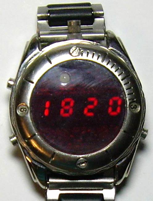
As the name implies, the main purpose of this device is to find out the current time and date. But it has many more useful features. The idea of its creation appeared after I came across a half-broken watch with a relatively large (for a wristwatch) metal case. I thought that I could insert a homemade watch there, the possibilities of which are limited only by my own imagination and skill. The result is a device with the following features:
1. Clock - calendar:
- Leap years count
Counting and output to the indicator hours, minutes, seconds, day of the week, day, month, year.
The presence of automatic adjustment of the current time, which is performed every hour (maximum values +/-9999 units, 1 unit = 3.90625 ms.)
Calculating the day of the week from a date (for the current century)
Automatic changeover to summer and winter time (switchable)
2. Two independent alarm clocks (when triggered, a melody sounds)
3. Timer with a resolution of 1 sec. (Maximum countdown time 99h 59m 59s)
4. Two-channel stopwatch with a counting resolution of 0.01 sec. (maximum counting time 99h 59m 59s)
5. Stopwatch with counting resolution 1 sec. (maximum counting time 99 days)
6. Thermometer in the range from -5°С. up to 55°С (limited by the temperature range of normal operation of the device) in 0.1°С increments.
7. Reader and emulator of electronic keys - tablets of the DS1990 type according to the Dallas 1-Wire protocol (memory for 50 pieces, in which there are already several universal “all-terrain vehicle keys”) with the ability to view the key code byte by byte.
8. IR remote control (only the "Take a picture" command is implemented) for digital cameras "Pentax", "Nikon", "Canon"
9. LED Flashlight
10. 7 melodies
11. Sound signal at the beginning of each hour (switchable)
12. Sound confirmation of button presses (switchable)
13. Battery voltage control with calibration function
14. Digital indicator brightness adjustment
Maybe such functionality is redundant, but I like universal things, well, plus moral satisfaction from the fact that this watch will be made by hand.
Schematic diagram of the clock
The device is based on the ATmega168PA-AU microcontroller. The clock ticks on the T2 timer, operating in asynchronous mode from clock quartz at 32768 Hz. The microcontroller is in sleep mode almost all the time (the indicator is off), waking up once a second to add this very second to the current time and falling asleep again. In active mode, the MK is clocked from the internal RC oscillator at 8 MHz, but the internal prescaler divides it by 2, as a result, the core is clocked from 4 MHz. For indication, four single-digit LED digital seven-segment indicators with a common anode and a decimal point are used. There are also 7 status LEDs, the purpose of which is as follows:
D1- Sign of a negative value (minus)
D2- Sign of a running stopwatch (blinking)
D3- Sign of the first alarm being turned on
D4- Sign of the second alarm clock on
D5- Sign of a sound signal at the beginning of each hour
D6- Sign of a running timer (blinking)
D7- Sign of low battery voltage
R1-R8 - current-limiting resistors of segments of digital indicators HG1-HG4 and LEDs D1-D7. R12, R13 - divider to control the battery voltage. Since the supply voltage of the clock is 3V, and the white LED D9 needs about 3.4-3.8V at the rated current consumption, it does not glow at full strength (but it is enough not to stumble in the dark) and therefore it is connected without a current limiting resistor. Elements R14, Q1, R10 are designed to control the infrared LED D8 (implementation of remote control for digital cameras). R19, R20, R21 are used for pairing when communicating with devices that have a 1-Wire interface. Management is carried out by three buttons, which I conditionally called: MODE (mode), UP (up), DOWN (down). The first of them is also designed to wake up the MK by an external interrupt (in this case, the indication turns on), so it is connected separately to the PD3 input. Pressing the remaining buttons is determined using the ADC and resistors R16, R18. If the buttons are not pressed within 16 seconds, then the MK falls asleep and the indicator goes out. When in mode “Remote control for cameras” this interval is 32 seconds, and with the flashlight on - 1 minute. Also, MK can be put to sleep manually using the control buttons. When the stopwatch is running with a counting resolution of 0.01 sec. The device does not go into sleep mode.
Printed circuit board
The device is assembled on a double-sided printed circuit board of round shape according to the size of the inner diameter of the watch case. But in the manufacture, I used two single-sided boards with a thickness of 0.35 mm. Again, this thickness was obtained by peeling it off from a double-sided fiberglass with a thickness of 1.5 mm. Boards then glued. All this was done because I did not have a thin double-sided fiberglass, and every millimeter of thickness saved in the limited internal space of the watch case is very valuable, and there was no need to combine in the manufacture of printed conductors using the LUT method. PCB drawing and parts location are in the attached files. On one side there are indicators and current-limiting resistors R1-R8. On the back are all the other details. There are two through holes for white and infrared LEDs.
Button contacts and battery holder are made of flexible springy sheet steel 0.2…0.3 mm thick. and tinned. Below are photos of the board from both sides:


Design, parts and their possible replacement
The microcontroller ATmega168PA-AU can be replaced by ATmega168P-AU, ATmega168V-10AU ATmega168-20AU. Digital indicators - 4 pieces KPSA02-105 super-bright red glow with a digit height of 5.08mm. Can be supplied from the same KPSA02-xxx or KCSA02-xxx series. (only not green ones - they will glow faintly) Other analogues of similar sizes with decent brightness are unknown to me. For HG1, HG3, the connection of segment cathodes differs from HG2, HG4, because it was more convenient for me for PCB layout. In this regard, a different character generator table is used for them in the program. Used resistors and capacitors SMD for surface mounting sizes 0805 and 1206, LEDs D1-D7 size 0805. White and infrared LEDs with a diameter of 3mm. There are 13 through holes on the board in which you need to install jumpers. DS18B20 with 1-Wire interface is used as a temperature sensor. LS1 - a conventional piezoelectric buzzer, inserted into the cover. With one contact, it is connected to the board with the help of a spring installed on it, with the other it is connected to the watch case by the cover itself. Quartz resonator from a wrist watch.
Programming, firmware, fuses
For in-circuit programming, there are only 6 round contact patches (J1) on the board, since a full-fledged connector did not fit in height. I connected them to the programmer using a contact device made from a PLD2x3 pin plug and springs soldered onto them, pressing them with one hand to the patches. Attached is a photo of the fixture.

I used it because during the debugging process I had to reflash the MK many times. With a one-time firmware, it is easier to solder thin wires connected to the programmer to the patches, and then solder them again. It is more convenient to flash the MK without a battery, but so that the power comes either from an external + 3V source or from a programmer with the same supply voltage. The program is written in assembler in the VMLAB 3.15 environment. Source codes, firmware for FLASH and EEPROM in the application.
The FUSE bits of the DD1 microcontroller must be programmed as follows:
CKSEL3...0 = 0010 - clocking from the internal RC oscillator 8 MHz;
SUT1...0 =10 - Start-up time: 6 CK + 64 ms;
CKDIV8 = 1 - frequency divider by 8 is disabled;
CKOUT = 1 - Output Clock on CKOUT disabled;
BODLEVEL2…0 = 111 - supply voltage control disabled;
EESAVE = 0 - erasing EEPROM during chip programming is disabled;
WDTON = 1 - No permanent activation of Watchdog Timer;
The rest of the FUSE - bits are better left untouched. FUSE bit is programmed if set to "0".
Flashing the EEPROM with the dump included in the archive is required.
The first cells of the EEPROM contain the initial parameters of the device. The table below describes the purpose of some of them, which can be changed within reasonable limits.
|
cell address |
Purpose |
Parameter |
Note |
|
|
The amount of battery voltage at which a signal about its low level occurs |
260($104) (2.6V) |
|||
|
coefficient for correcting the value of the measured battery voltage |
||||
|
sleep time interval |
1 unit = 1 sec |
|||
|
time interval for switching to sleep mode when the flashlight is on |
1 unit = 1 sec |
|||
|
the amount of time to enter sleep mode when in camera remote control mode |
1 unit = 1 sec |
|||
|
Numbers of IButton keys are stored here |
A little clarification on the points:
1 point. This indicates the amount of voltage on the battery, at which the LED will light up, signaling its low value. I set 2.6V (parameter - 260). If you need something else, for example 2.4V, then you need to write 240 ($ 00F0). The low byte is entered into the cell at the address $0000, respectively, the high byte is entered into $0001.
2 point. Since I did not install a variable resistor on the board to adjust the accuracy of measuring the battery voltage due to lack of space, I introduced software calibration. The calibration procedure for accurate measurement is as follows: initially, a coefficient of 1024 ($ 400) was recorded in this EEPROM cell, you need to put the device into active mode and look at the voltage on the indicator, and immediately measure the real voltage on the battery with a voltmeter. The correction factor (K), which must be set, is calculated by the formula: K \u003d Up / Ui * 1024 where Up is the real voltage measured by the voltmeter, Ui is the voltage that the device itself measured. After calculating the coefficient "K", it is entered into the device (as it is done in the instruction manual). After calibration, my error did not exceed 3%.
3 point. Here you can set the time after which the device will go into sleep mode if no buttons are pressed. I have 16 sec. If we suppose it is necessary that it falls asleep in 30 seconds, then it is necessary to write down 30 ($ 26).
In paragraphs 4 and 5 it is similar.
6 point. The address $0030 stores the zero key family code (dallas 1-Wire), then its 48 bit number and CRC. And so 50 keys in series.
Setting, features of work
Setting up the device comes down to calibrating the battery voltage measurement as described above. It is also necessary to detect the deviation of the clock for 1 hour, calculate and enter the appropriate correction value (the procedure is described in the instruction manual).
The device is powered by a CR2032 (3V) lithium battery and consumes about 4 μA in sleep mode, and 5 ... 20 mA in active mode, depending on the brightness of the indicator. With a daily five-minute use of the active mode, the battery should last for about 2 .... 8 months, depending on the brightness. The watch case is connected to the minus of the battery.
Key reading was tested on the DS1990. The emulation has been tested on METAKOM intercoms. Under serial numbers from 46 to 49 (the last 4) are flashed (all keys are stored in EEPROM, they can be changed before flashing) universal keys for intercoms. The key registered at number 49 opened all the METAKOM intercoms that I came across, I did not have a chance to test the rest of the universal keys, I took their codes from the network.
Remote control for cameras was tested on models Pentax optio L20, Nikon D3000. Canon could not be obtained for review.
The user manual occupies 13 pages, so I did not include it in the article, but put it in the appendix in PDF format.

The archive contains:
Scheme in and GIF;
PCB drawing and arrangement of elements in the format ;
Firmware and source codes in assembler;
List of radio elements
| Designation | Type | Denomination | Quantity | Note | Score | My notepad |
|---|---|---|---|---|---|---|
| DD1 | MK AVR 8-bit | ATmega168PA | 1 | PA-AU | To notepad | |
| U2 | temperature sensor | DS18B20 | 1 | To notepad | ||
| Q1 | MOSFET transistor | 2N7002 | 1 | To notepad | ||
| C1, C2 | Capacitor | 30 pF | 2 | To notepad | ||
| C3, C4 | Capacitor | 0.1uF | 2 | To notepad | ||
| C5 | electrolytic capacitor | 47uF | 1 | To notepad | ||
| R1-R8, R17 | Resistor | 100 ohm | 9 | To notepad | ||
| R9 | Resistor | 10 kOhm | 1 | To notepad | ||
| R10 | Resistor | 8.2 ohm | 1 | To notepad | ||
| R11 | Resistor | 300 ohm | 1 | To notepad | ||
| R12 | Resistor | 2 MΩ | 1 | To notepad | ||
| R13 | Resistor | 220 kOhm | 1 | To notepad | ||
| R14 | Resistor | 30 kOhm | 1 | To notepad | ||
| R15, R19 | Resistor | 4.7 kOhm | 2 | To notepad | ||
| R16 | Resistor | 20 kOhm | 1 |
Not long ago, there was a need to have a clock in the house, but only electronic, since I don’t like analog clocks, because they tick. I have quite a bit of experience in soldering and etching circuits. After scouring the Internet and reading some literature, I decided to choose the simplest scheme, since I do not need an alarm clock.
I chose this scheme because it is easy make a watch with your own hands
Let's get started, so what do we need in order to make ourselves a watch with our own hands? Well, of course, hands, the ability (not even great) to read circuits, a soldering iron and details. Here is a complete list of what I used:
Quartz at 10 MHz - 1 pc, ATtiny 2313 microcontroller, 100 Ohm resistors - 8 pcs, 3 pcs. 10 kOhm, 2 x 22 pF capacitors, 4 transistors, 2 buttons, LED indicator 4-bit KEM-5641-ASR (RL-F5610SBAW/D15). I performed the installation on a one-sided textolite.
But there is a flaw in this scheme.: the outputs of the microcontroller (hereinafter MK), which are responsible for managing the discharges, receive a pretty decent load. The current in the total amount is much higher than the maximum current of the port, but with a dynamic indication, the MK does not have time to overheat. In order for the MK not to fail, we add 100 Ohm resistors to the discharge circuits.
In this scheme, the indicator is controlled according to the principle of dynamic indication, according to which the indicator segments are controlled by signals from the corresponding outputs of the MC. The repetition frequency of these signals is more than 25 Hz and because of this, the glow of the indicator numbers seems to be continuous.
Electronic clock, made according to the above scheme, can only show time (hours and minutes), while seconds are shown by a dot between segments which is blinking. To control the operating mode of the clock, its structure provides push-button switches that control the setting of hours and minutes. This circuit is powered by a 5V power supply. In the manufacture of the printed circuit board, a 5V zener diode was included in the circuit.

Since I have a 5V power supply, I excluded the zener diode from the circuit.
To make a board, a circuit was applied using an iron. That is, the printed circuit was printed on an inkjet printer using glossy paper, it can be taken from modern glossy magazines. After that, the textolite of the required dimensions was cut out. I got the size 36 * 26 mm. Such a small size due to the fact that all the parts are selected in the SMD package.
The board was etched using ferric chloride (FeCl 3 ). By the time, the etching took about an hour, since the bath with the paid one was on the fireplace, the high temperature affects the etching time, not used copper in the board. But do not overdo it with the temperature.
While the process of etching was going on, in order not to rack my brains and not write the firmware for the clock, I went to the Internet and found a firmware for this scheme. How to flash MK can also be found on the Internet. I used a programmer that only flashes MK from ATMEGA.
And finally, our board is ready and we can start soldering our clock. For soldering, you need a 25 W soldering iron with a thin tip in order not to burn the MK and other parts. We carry out soldering carefully and preferably from the first time we solder all the legs of the MK, but only separately. For those who are not in the know, know that the parts made in the SMD package have tin on their terminals for fast soldering.
And this is what the board looks like with soldered parts.

Homemade electronic clock, element base - part 1, time measurement
- DIY or DIY
Probably, every geek who is fond of homemade electronics sooner or later comes up with the idea of making his own unique watch. The idea is quite good, let's figure out how and on what to make them better. As a starting point, we will assume that a person knows how to program microcontrollers, understands how to send 2 bytes over an i2c or serial port, and can solder several wires together. In principle, this is enough.
It is clear that the key function of the watch is the measurement of time (who would have thought, right?). And it is desirable to do this as accurately as possible, there are several options and pitfalls.
So, what methods of time measurement available in hardware can we use?
CPU Built-in RC Oscillator
The simplest idea that can come to mind is to simply set up a software timer and let it count down the seconds. Well, this idea doesn't work. Of course, the clock will work, only the accuracy of the built-in generator is not regulated in any way, and can “float” within 10% of the nominal value. It is unlikely that anyone needs hours that go 15 minutes a month.Real time module DS1307
A more correct option, which is also used in most "folk" products, is a real-time clock. The microcircuit communicates with the microcontroller via I2C, requires a minimum of binding (quartz and a pair of resistors). The issue price is about 100 rubles per chip, or about $ 1 on ebay for a ready-made board with a microcircuit, a memory module and a battery connector.Diagram from the datasheet:
No less important, the microcircuit is produced in a DIP package, which means that any novice radio amateur can solder it. The built-in battery keeps the clock running even if the power has been turned off.
It would seem that everything is fine, if not for one problem - low accuracy. The approximate accuracy of watch quartz is 20-30ppm. The designation ppm - parts per million, shows the number of parts per million. It would seem that 20 millionths is super, however, for a frequency of 32768 Hz, it turns out 20 * 32768 / 1000000 = ± 0.65536 Hz, i.e. already half a dick. By simple calculations, it can be seen that the generator with such a difference per day “clicks” extra (or missing) 56 thousand cycles, which corresponds to 2 seconds per day. Quartz is different, some users wrote about an error of 5 seconds a day. Somehow it’s not very accurate - in a month such hours will leave at least a minute. This is already a decent difference, noticeable to the naked eye (when the grandmother's favorite series starts at 11.00, and the clock shows 11.05, the developer of such watches will be uncomfortable in front of relatives).
However, since the temperature in the room is more or less stable, and the frequency of the quartz will not change much, you can add software correction. Another advice given on the forums is to use clock quartz from old motherboards, according to reviews, they are quite accurate there.
Real time module DS3231
We are not the first who asked the question of accuracy, and Dallas, having met the wishes, released a more advanced module - DS3231. It is called "Extremely Accurate Real Time Clock" and has a built-in temperature corrected oscillator. The accuracy is 10 times higher, and is 2ppm. The price of the issue is slightly higher, but the microcircuit case is designed for SMD mounting, soldering is not so convenient, but you can buy a ready-made board on eBay.
(photo from seller's website)
An accuracy of 6 seconds per month is already a good result. But we will go further - ideally, clocks in the 21st century do not need to be adjusted at all.
Radio module DCF-77
The method is rather exotic, but for the sake of completeness, it must be mentioned. Few people know, but the exact time signals have been transmitted by radio since the 70s. The DCF-77 transmitter is located in Germany near Frankfurt, and on the 77.5KHz VLF frequency, precise time stamps are transmitted (yes, they already had wall and table clocks 20 years ago that did not need to be adjusted).The method is good because the circuit has a low power consumption, so even wristwatches with this technology are now being produced. You can buy a ready-made DCF-77 reception board on ebay, the issue price is $20.

Many clocks and weather stations have the ability to receive DCF-77, the only problem is that the signal practically does not reach Russia. Coverage map from Wikipedia:

As you can see, only Moscow and St. Petersburg are on the border of the reception area. According to the owners, only sometimes the signal can be received, which, of course, is not suitable for practical use.
GPS module
If the clock is not far from the window, then a very real method of obtaining the exact time is a GPS module. These modules can be bought inexpensively on ebay (issue price $10-15). For example, Ublox NEO-6M connects directly to the serial pins of the processor and outputs NMEA strings at 9600 speed.
The data comes in approximately the following format "$GPRMC,040302.663,A,3939.7,N,10506.6,W,0.27,358.86,200804,*1A", and parsing them even for a weak Arduino is not difficult. Patriots, by the way, can purchase the more expensive Ublox NEO-7N module, which supports (according to reviews) both GPS and Glonass.
Obviously, the GPS module does not know anything about different time zones, so the developer will have to think over their calculation and change of summer / winter time. Another disadvantage of using GPS is the relatively high power consumption (however, some modules can be put into "sleep mode" by separate commands).
WiFi
And finally, the last (and most obvious at the moment) way to get the exact time is to take it from the Internet. There are two approaches here. The first, and most simple, is to use something like Raspberry PI with Linux as a clock board, then you don’t need to do anything, everything will work out of the box. If you want "exotics" - then the most interesting option is the esp8266 module.
This is an inexpensive (issue price of about 200 rubles on ebay) WiFi module that can communicate with the server via the serial port of the processor, if desired, it can also be reflashed (there are quite a lot of third-party firmware), and part of the logic (for example, polling the time server) is done in the module itself. A lot of everything is supported by third-party firmware, from Lua to C ++, so there are enough options to “stretch your brains”.
At this point, the topic of measuring time can probably be closed. In the next part, we will take a closer look at processors, and ways to display time.
Hours with a sound signal of an alarm clock the timer for control of household appliances.
A timer is a device that, at a set time, turns on or off the equipment with its switching contacts. Real-time timers allow you to set the time of operation at the set time of day. The simplest example of such a timer would be an alarm clock.
The scope of the timer is extensive:
- management of lighting devices;
- management of watering of house and garden plants;
- ventilation control;
- aquarium management;
- control of electric heaters and so on.
The proposed timer can be quickly and inexpensively made even by a beginner radio amateur.
I made it based on the clock constructor. ()
I needed to use a timer to control the watering of plants in the country.
See the entire manufacturing process in the video:
List of tools and materials
- any electronic watch with an alarm signal;
-screwdriver;
- scissors;
- soldering iron;
- cambric;
- two relays for 12V;
- 12V power supply from the adapter;
- connecting wires;
- foil textolite for printed circuit board or breadboard;
- time relay industrial or homemade;
-resistor;
- KT815 transistors (or analogues);
-diode.
Step one. Unsoldering the timer board.
Timer circuit
All that is needed is to solder the components to the breadboard according to the scheme and solder two wires from the clock piezo emitter. We collect the simplest circuit with an intermediate relay and a transistor switch. When the first pulse of a sound signal is given from the clock, relay P1 is turned on, the normally open contact closes and turns on the load, simultaneously through the second normally open contact of the relay P1 and the normally closed contact of the time relay, relay P1 self-locks. Together with the load, the time relay RV is turned on - the countdown of the specified load operation time begins. At the end of this time, PB opens the contact and relay P1 is de-energized, the load is turned off. The circuit is ready for the next cycle. The diode serves to prevent a reverse pulse in the clock circuit (you can use any low-power diode). LED for indicating the inclusion of the load. In this circuit, you need an intermediate relay with two normally open contacts, but I didn’t have it - I used two Chinese relays (the coils are connected in parallel). If the load is more powerful, then you need to use a relay with more powerful contacts. I had a 12V adapter, I installed its circuit directly on the breadboard. In principle, any low-power 12V power source can be used.

If shorter, then the clock turns on the load and the time relay is turned off after the exposure time has elapsed.
If you do not have an industrial time relay, then you can do it yourself according to a simple scheme. With an increase in the capacitance of the capacitor C1, the operating time of the relay increases.

Step two. Checking the operation of the timer.
My circuit worked the first time I turned it on.
It remains to set the alarm time. My watch has two alarm time settings. For my case, it’s just enough to turn on watering, for example, in the morning at 7 o’clock for an exposure of one hour, and in the evening at 20 o’clock, water again. When the clock buttons are pressed, beeps are emitted, therefore, when setting, the timer circuit must be de-energized to prevent false positives. My watch has a “chimes” function - every hour from 8 to 20 hours, that is, in addition to the alarm clock, you can use these signals if necessary. If not needed, that is, the "chimes" function is disabled.
This is how the design of the weekend turned out. It was interesting to run in a new scheme, so everything was done quickly. In the future, it will be necessary to make a case and place a board and a time relay there. To make such a timer on your own is within the power of a beginner without spending a lot of time and money. And where to apply them already decide for yourself.
All the work took a couple of weekend evenings and 75 rubles (
On sale you can find many different models and options for electronic digital watches, but most of them are designed for indoor use, since the numbers are small. However, sometimes it is required to place the clock on the street - for example, on the wall of a house, or in a stadium, square, that is, where they will be visible at a great distance by many people. For this, this circuit of a large LED clock was developed and successfully assembled, to which you can connect (through internal transistor switches) LED indicators of arbitrarily large size. You can enlarge the circuit diagram by clicking on it:

Description of the watch
- Clock. In this mode, there is a standard view of the time display. There is a digital correction of the accuracy of the watch.
- Thermometer. In this case, the device measures the temperature of the room or the air outside, from one sensor. Range from -55 to +125 degrees.
- Power supply control is provided.
- Output of information to the indicator alternately - clock and thermometer.
- To save the settings and settings in the event of a 220V power outage, a non-volatile memory is used.

The basis of the device is the ATMega8 MK, which is flashed by exposing fuses according to the table:

Operation and clock management
When you turn on the clock for the first time, the screen will display an advertising splash screen, and then switch to the time display. Pushing the button SET_TIME the indicator will go in a circle from the main mode:
- display mode for minutes and seconds. If in this mode you simultaneously press the button PLUS and MINUS, then seconds will be reset;
- setting the minutes of the current time;
- setting the clock of the current time;
- symbol t. Setting the duration of the clock display;
- symbol o. Time for displaying the symbols for indicating the external temperature (out);
- the value of the daily correction of the accuracy of the watch. Symbol c and correction value. Setting limits from -25 to 25 sec. The selected value will be daily at 0 hours 0 minutes and 30 seconds added to or subtracted from the current time. For more details, read the instructions that are in the archive with firmware files and printed circuit boards.

Clock setting
Holding buttons PLUS/MINUS do an accelerated setting of values. After changing any settings, after 10 seconds, the new values will be written to non-volatile memory and will be read from there when the power is turned on again. The new settings take effect during installation. The microcontroller monitors the presence of the main power supply. When it is turned off, the device is powered from an internal source. The Redundant Power Module schematic is shown below:

To reduce the current consumption, the indicator, sensors and buttons are turned off, but the clock itself continues to count time. As soon as the mains voltage of 220V appears, all indication functions are restored.

Since the device was conceived as a large LED clock, it has two displays: a large LED for the outdoors, and a small LCD for easy setup of the main display. The large display is located at a distance of several meters from the control unit and is connected by two cables of 8 wires. To control the anodes of the external indicator of the indicators, transistor keys are used according to the scheme given in the archive. Project authors: Aleksandrovich & SOIR.