Under renovation household appliances or other electronic devices: monitor, printer, microwave oven, computer power supply or car generator(for example, Valeo, BOSCH or BPV), etc. there is a need to check the integrity of the elements. Let's talk in detail about testing diodes.
Given the diversity of these radioelements, there is no single method for checking their performance. Accordingly, each class has its own way of testing. Consider how to test a schottky diode, photodiode, high frequency, bidirectional, etc.
With regard to test instruments, we will not consider exotic ways checks (for example, a battery and a light bulb), but we will use a multimeter (even such simple model like DT-830b) or tester. These devices are almost always at home with a radio amateur. In some cases, you will need to assemble a simple circuit for testing. Let's start with the classification.
Classification
Diodes are simple semiconductor radio elements based on p-n junction a. The figure shows a graphical representation of the most common types of these devices. The anode is marked with “+”, the cathode is marked with “-” (given for clarity, in the diagrams, a graphic designation is enough to determine the polarity).
Accepted designationsTypes of diodes indicated in the figure:
- A - rectifier;
- B - zener diode;
- C - varicap;
- D - microwave diode (high voltage);
- E - inverted diode;
- F - tunnel;
- G - LED;
- H is a photodiode.
Now consider the verification methods for each of the listed types.
Checking the rectifier diode and zener diode
The protective diode, as well as the rectifier (including power) or Schottky, can be checked with a multimeter (or use an ohmmeter), for this we put the device in the continuity mode as shown in the photo.

probes measuring instrument we attach to the conclusions of the radio element. When connecting the red wire ("+") to the anode, and the black wire ("-") to the cathode, the display of the multimeter (or ohmmeter) will display the threshold voltage value of the diode under test. After we change the polarity, the device should show indefinitely great resistance. In this case, you can state the health of the element.
If the multimeter registers a leak when connected back, then the radio element has “burned out” and needs to be replaced.
Note that this testing technique can be used to test diodes on a car alternator.
Testing a zener diode is carried out according to a similar principle, however, such a test does not allow you to determine whether the voltage is stabilized at a given level. Therefore, we need to assemble a simple circuit.

Designations:
- BP - adjustable block power supply (displaying the load current and voltage);
- R - current-limiting resistance;
- VT - tested zener diode or avalanche diode.
The principle of verification is as follows:
- we assemble the circuit;
- set the multimeter mode, which allows you to measure constant pressure up to 200 V;

- turn on the power supply and begin to gradually increase the voltage until the ammeter on the power supply shows that current flows through the circuit;
- we connect the multimeter, as shown in the figure and measure the stabilization voltage.
Varicap testing
Unlike conventional diodes, for varicaps, the p-n junction has a non-constant capacitance, the value of which is proportional to reverse voltage. The open or short test for these elements is carried out in the same way as for conventional diodes. To check the capacitance, you will need a multimeter that has a similar function.

For testing, you will need to set the appropriate multimeter mode, as shown in photo (A) and insert the part into the capacitor connector.
As one of the commentators of this article correctly noted, it is indeed possible to determine the capacity of a varicap without operating rated voltage impossible. Therefore, if there is a problem with identification by appearance, you need to collect a simple prefix for a multimeter (I repeat for critics, namely a digital multimeter with the function of measuring the capacitance of checking capacitors, for example, UT151B).

Designations:
The device needs to be configured. She's pretty simple assembled device, connects to a measuring instrument (multimeter with capacitance measurement function). Power must be supplied from a stabilized power source (important) with a voltage of 9 volts (for example, a Kron battery). By changing the capacitance of the subscript capacitor (C2), we achieve a reading on the indicator of 100 pF. We will subtract this value from the instrument reading.
This option is not ideal, the need for it practical application is doubtful, but the diagram clearly demonstrates the dependence of the varicap capacitance on the rated voltage.
Suppressor test (TVS diode)
Protective diode, it is also a restrictive zener diode, a suppressor and a TVS diode. These elements are of two types: symmetrical and asymmetrical. The former are used in chains alternating current, the second - permanent. If we briefly explain the principle of operation of such a diode, then it is as follows:
Increasing the input voltage causes a decrease internal resistance. As a result, the current in the circuit increases, which causes the fuse to blow. The advantage of the device lies in the speed of reaction, which allows you to take on excess voltage and protect the device. The response speed is the main advantage of the protective (TVS) diode.
Now for the verification. It is no different from a conventional diode. True, there is an exception - Zener diodes, which can also be attributed to the TVS family, but in fact it is a fast zener diode operating according to the “avalanche breakdown” mechanism (Zener effect). But, the health check rolls down to the usual dialing. The creation of trigger conditions leads to the failure of the element. In other words, the way to check protective functions There is no TVS diode, it's like checking a match (whether it's good or not) by trying to set it on fire.
High Voltage Diode Testing
Checking the high-voltage diode of a microwave oven in the same way as a regular one will not work, in view of its features. To test this element, you will need to assemble a circuit (shown in the figure below) connected to a 40-45 volt power supply.

A voltage of 40-45 volts will be enough to check most elements of this type, the testing technique is the same as for ordinary diodes. The resistance value R should be in the range from 2 kOhm to 3.6 kOhm.
Tunnel and Reversed Diodes
Considering that the current flowing through a diode depends on the voltage applied to it, testing consists in analyzing this dependence. To do this, you need to assemble a circuit, for example, such as is shown in the figure.

Item List:
- VD is the tunnel type diode under test;
- Up - any galvanic power source with a discharge current of about 50 mA;
- Resistances: R1 - 12Ω, R2 - 22Ω, R3 - 600Ω.
The measurement range set on the multimeter should not be less than the maximum diode current, this parameter is indicated in the datasheet of the radio element.
Video: An example of checking a diode with a multimeter
Testing algorithm:
- installed maximum value on variable resistor R3;
- the element under test is connected, observing the polarity indicated on the diagram;
- decreasing the value of R3, we observe the readings of the measuring device.
If the element is in good condition, during the measurement process the device will show an increase in current up to I max diode, after which sharp decrease this value. With a further increase in voltage, the current will decrease to I min, after which it will begin to grow again.
LED Testing
Testing LEDs is practically no different from testing rectifier diodes. How to do this was described above. We check the LED strip (more precisely, its smd elements), infrared LED, as well as laser, using the same method.
Unfortunately, a powerful radio element of this group, which has an increased operating voltage, cannot be checked in this way. In this case, you will additionally need a stabilized power supply. The testing algorithm is as follows:
- assemble the circuit as shown in the figure. The operating voltage of the LED is set to the power supplies (indicated in the datasheet). The measurement range on the multimeter must be up to 10 A. Note that you can use Charger as a PSU, but then it is necessary to add current-limiting resistance;

- we measure rated current and turn off the power supply;
- set the multimeter mode, which allows you to measure a constant voltage up to 20 V, and connect the device in parallel with the element under test;
- turn on the power supply and remove the parameters of the operating voltage;
- we compare the received data with those indicated in the datasheet, and based on this analysis, we determine the performance of the LED.
Checking the photodiode
With a simple check, the reverse and forward resistance of the radio element placed under the light source is measured, after which it is darkened and the procedure is repeated. For more accurate testing, you will need to remove the current-voltage characteristic, this can be done using a simple circuit.

To illuminate the photodiode during testing, you can use an incandescent lamp with a power of 60 W or more as a source of illumination or bring the radio component to a chandelier.
Photodiodes sometimes have a characteristic defect, which manifests itself in the form of a chaotic change in current. To detect such a failure, it is necessary to connect the element under test as shown in the figure, and measure the amount of reverse current for a couple of minutes.

If during the testing process the current level remains unchanged, then the photodiode can be considered working.
Testing without desoldering.
As practice shows, it is not always possible to test a diode without soldering when it is on the board, like other radio components (for example, a transistor, capacitor, thyristor, etc.). This is due to the fact that the elements in the circuit can give an error. Therefore, before checking the diode, it must be desoldered.
Although LED sources lights have a much longer service life than most analogues, they also fail. The reason for this can be both damage and resource depletion. simple and effective way make sure that there is a malfunction - check the LED with a tester in the “ringing” mode. In addition, the health of the LED must be checked before mounting it on the board.
How is the verification carried out?
LEDs operate on low voltage electrical current, which is converted in power supplies and electronic circuits. However, before installing the LED element in the circuit, you need to make sure that it is operational so as not to waste time dismantling it in case of a breakdown. For this purpose, a multimeter is used, which allows you to ring the device in the LED test mode. The check is based on the fact that inside the LED there is semiconductor junction, due to which the supply of current under the operating voltage will cause it to catch fire.
Thus, to ring the LED element, you need:
- Use the mode knob to set the multimeter to the LED test mode.
- Connect the probes of the device to the electrodes of the LED in compliance (red - to the anode, black - to the cathode). If the polarity is unknown and reversed, nothing bad will happen. Therefore, you should try to rearrange the probes in places if the LED does not light up.
- A figure will appear on the display of the measuring device, showing the voltage drop at the p-n junction.

However, in rare cases, a situation arises when the working LED lights up during testing, the multimeter displays the operating parameters, but after mounting in the circuit, the LED element does not glow with sufficient brightness. This problem associated with a crystal malfunction that cannot be corrected on its own. It must be replaced and disposed of.
Many models of multimeters are equipped with a special PNP block, with which you can ring a free LED without using probes. PNP is a socket with several holes into which the electrodes of the LED element are inserted. The electrical characteristics of the unit ensure that a healthy LED glows.
To test an LED for PNP, you need to connect it with the correct polarity. positive electrode(anode) is inserted into connector E (emitter), and the negative (cathode) is inserted into C (collector).

To check the LED with a multimeter without soldering from working scheme, you need to design an adapter from a conductive material. The test itself is no different from the one described above. The main inconvenience is that it is not possible to insert the electrodes of the LED device into the corresponding sockets. To do this, they are lengthened with the help of a thin conductor, which can be a sewing needle untwisted paper clip or a piece of cable. To check, they are soldered to the LED electrodes and called either with probes or through a PNP block. After making sure that the LED is in working condition, the conductors will need to be carefully unsoldered.
Now in electrical stores you can buy special LED testers. They are made in the form of a device with its own power supply and several connectors suitable for connecting LEDs of various designs.
Checking the LED Strip
The LED strip consists of many LED devices combined into small sections. The LEDs are arranged in series within the sections, and the sections are arranged among themselves. Due to this, it is possible to cut the tape to the desired length. To test the LED strip, you need to apply current to the power wires. Everything is simple here - the tape is on, which means it is working. If the entire tape does not light up when power is applied, it is necessary to check the resistance of the supply wires with a multimeter for a break.
If, when connecting the power to led strip do not light up individual groups LEDs, you need to ring them separately. In such a situation, you need to check them separately by the resistor, which is mounted in the circuit in front of each group. The reference value for the test should be the nominal value of the resistance.

Checking LED lamps
LED energy-saving lamps produced in an external design similar to traditional incandescent lamps, however internal organization is very different. At the beginning of the working circuit, a driver is installed - electronic component, converting the incoming current with a voltage of 220 V to desired parameters. Drivers for each model can be very different from each other, they use different electrical characteristics and number of elements. Because of this check led light bulb not possible with a multimeter. It is necessary to use a special tester with a circuit designed to diagnose various light bulbs. Its body has connectors for screwing in fixtures, when connected, the device reports the test result with an audible signal.
LEDs in recent times have become incredibly widespread. Today, LEDs can be found not only in high-tech devices, but also in ordinary household lighting fixtures.
Powerful LEDs COM SMB can be purchased at affordable price. However, before making a piece purchase, it is necessary to test the LED for operability.
Naturally, before buying or before directly installing a semiconductor element into a board, it is necessary to conduct it full check. This will avoid wasting time.
So, how can you check the LED home master at home? This will require the following:
- magnifying glass;
- documentation for the LED (if necessary);
- tester (multimeter);
- power supply.
The fact is that to test a low-power LED, you can do without a power source. To do this, you just need to connect it directly to the circuit.
Installing the tester special mode check the LEDs and check the element. A bright glow should serve as a signal. However, it is worth remembering that the tester must be connected strictly to certain terminals (anode, cathode).
Their definition is the main task. As a rule, the cathode is a short lead, the anode is a long one. But it may happen that both outputs will be the same length. In this case, you need to look at the element in the light.
Through the glass it will be possible to see the bases of the electrodes. The big one is the cathode. However, this rule does not always work. Only detailed documentation for the element will give full confidence.

Most multimeters have a special slot, including an element in which it becomes clear whether it is working or not. When connecting, remember that hole C is the collector and hole E is the emitter.
For powerful LED models, this test may not be suitable. In this case, it is necessary to use any power source (with a given current value, which has the necessary limitations in accordance with the power of the element).
LEDs have been used in electrical engineering for a long time. But if earlier they were used exclusively as a variety of indicators, today the scope of these elements has expanded significantly.
Remote control signals are transmitted using infrared diodes. remote control and all kinds of sensors, they are also used in surveillance cameras, instrumentation and other devices.
Another variety - super-bright elements, having finally learned to glow for real, quite confidently crowd out traditional light sources - incandescent lamps and even more advanced and economical fluorescent lamps.
It is unlikely that at least someone these days has not heard of, for example), and almost everyone has a flashlight with this type of light bulbs. One way or another, LEDs are being used more and more, and therefore we are increasingly faced with the need (when trying to find out the cause of a breakdown of a device) to check their performance.
superbright
Checking yellow, blue and white LEDs used as light sources and called super-bright ones is not particularly difficult. To do this, it is enough to connect the terminals of the element to a power source with a voltage of 3 to 4.2 V (no more!).
As such a source, it is most convenient to use a pair of 1.5-volt batteries connected in series. But the fact of the matter is that they are not always available at hand.
Is it possible to carry out a check using a conventional multimeter, which every radio amateur has, especially since in modern versions Does this device have a special mode for testing diodes?
It turns out that there is such a possibility. Although the mentioned mode, due to insufficient power food, in this case will not help. Instead, we will use transistor parameter measurement mode, which is also included in each modern model digital multimeter.
Digital multimeter
To study transistors, the tester is equipped with a special connector to which the element's leads are connected. It is labeled PHP letters. The cathode of the ultra-bright LED (this is the shortest lead) must be connected instead of the collector (position "C" on the connector), and the anode - instead of the emitter (position "E"). If the element is good, it will start to glow, and the position of the measurement mode switch in this case does not matter.
In most cases, the lighting element is a part and plugging it directly into the PHP connector without soldering will not work. It is not possible to check it with probes, since they cannot be connected to the connector.
You can solve the problem by making a simple design consisting of an adapter and probes connected to it from an old or broken multimeter.

Standard multimeter leads
How to make probes with an adapter to a PHP connector
We need very little:
- two unnecessary probes (plugs must be cut off);
- a small fragment of double-sided textolite;
- a pair of metal clips;
- (required for ease of use, but the device will work without it).
A paper clip should be soldered to the textolite plate on each side, after bending their ends 180 degrees. You will get something like an electric plug.

Textolite plates
The thickness of the textolite fragment should be such that the distance between the pins of the "plug" corresponds to the distance between the inputs "C" and "E" on the PHP connector. That's all, the adapter is ready. It remains to solder to it (again on both sides) the wires from the probes.
It is better to place the textolite between the paper clips asymmetrically. Thanks to this, it will be easier to understand which side should include the adapter in the transistor connector of the multimeter, so as not to reverse the polarity.
The design can be supplemented with an SMD type LED, which will be assigned the function of an indicator.
How to make a dipstick with your own hands
If you don’t have standard probes that could be sacrificed, homemade ones can be used instead. To make them you will need:
- a pair of needles;
- tinned wire with a diameter of 0.2 mm (removed from the stranded wire).
The wire should be wound around the needle so that its turns fit snugly together, and then soldered. It is very convenient to use nickel-plated needles for this purpose., then soldering is done as easily and quickly as possible. Often such a probe provides better contact than a standard one.
infrared
As we purchase consumer electronic devices, each of us gradually becomes the owner of a whole battery of remote controls. As long as the equipment obediently responds to your commands, there is nothing to worry about.
But it is quite likely that  when desperate attempts to change the channel or turn down the brightness of the chandelier do not lead to any result. In such cases, first check the status of the infrared LED, through which the remote control transmits your requirements to the main device.
There are several ways to check the IR LED in the remote control or other device. Let's start with the simplest:
Direct the radiation of the diode into the lens digital camera. Not only a camera is suitable, but also a phone, a laptop, a DVR, a web camera, etc. IR radiation is absolutely invisible to the human eye, but electronic "eyes" register it very well. If the LED performs its functions properly, purple flashes will be observed on the matrix.
In the absence of a gadget that can shoot, a suspicious LED can be dismantled, replacing it with a super-bright or SMD-type LED. Just make sure that the operating voltage of both elements is the same.
If the test LED emits a visible light emission(most likely, it will be dim), which means that the IR LED has already served its purpose.
More hard way, but neither a camera nor soldering is required. You can use an infrared photodiode. When infrared radiation hits the sensor of this element, a potential difference is formed at its terminals.
To test any IR LED, its radiation must be directed to the sensitive zone of the photodiode, previously connected to open entrance oscilloscope.
If at the same time pulse curves appear on the screen of the device, the tested LED is in working condition. If you observe complete calm, then it's time to buy a new IR LED.
Diagnostics of the LED in the flashlight
Or other types are enough reliable device, but he is not immune from breakdowns. If even after installing new batteries, the glow remains weak or completely absent, it is necessary to check the performance of the LEDs and their drivers.
Before diagnosing a flashlight, it would be useful to check the batteries (even if they have just been unpacked) on some known working device. To some, this advice will seem banal, but quite often, as practice has shown, the reason for "showdowns" with consumer electronics become defective batteries, which the home craftsman guesses last.
Flashlight check is performed in the following sequence:
- We unscrew the cover or conical part in the front of the case.
- Remove the LED module.
- There are two LEDs on the board. pads to which the red and black wires are connected. The red wire corresponds to the positive polarity (marking "+" on the board), and the black wire - negative (marking "-"). In accordance with the polarity, a voltage of 3 - 4 V should be applied to the contacts for a short time (no more than 4.2 V!). If the brightness of the LED does not change, then it needs to be replaced. Otherwise (the LED lights up properly), the driver must be replaced.
- Replacing an LED is only possible if its board is attached to the LED module capsule with screws. If the board is planted on hot-melt adhesive, the replacement will be impractical, in this case the entire module is changed.

This is what the LED module looks like in the Magicshine flashlight
After unscrewing the board, unsolder the LED, and then install a new one.
In flashlights, LEDs are mounted on aluminum radiators. For effective heat dissipation, a fresh layer of a special heat-conducting paste, also called thermal paste, should be applied to the heatsink before installing a new LED on the heatsink. The old dried layer, even if it is quite thick, cannot be reused and must be removed.
Visually checking a separate LED and the simplicity of the tester device is demonstrated in the following video from the largest supplier of electrical equipment in Russia.
Often in the event of a breakdown of one or another electronic device without hesitation, we carry the victim to the repair, where we are presented with a solid bill. Meanwhile, the cause of the accident may be just a failure of the LED, which can be easily replaced on your own.
Thus, the ability to check the performance of these elements, which are used quite widely today, will save money and reduce repair time to a minimum.
And the LED multimeter? It turns out that everything is very simple. This is exactly what we will talk about in our article.
How to test a diode with a multimeter
In the photo below we have a simple diode and an LED.
We take ours and put the twist on the diode test icon. I talked about this and other icons in more detail in the article how to measure current and voltage with a multimeter.

I would like to add a few words about the diode. A diode, like a resistor, has two ends. And they are called cathode and anode. If a plus is applied to the anode and a minus to the cathode, then it will flow calmly through the diode, and if a plus is applied to the cathode and minus to the anode, the current will NOT flow. This is the operating principle on which all diodes work.
We check the first diode. We put one probe of the multimeter on one end of the diode, the other probe on the other end of the diode.
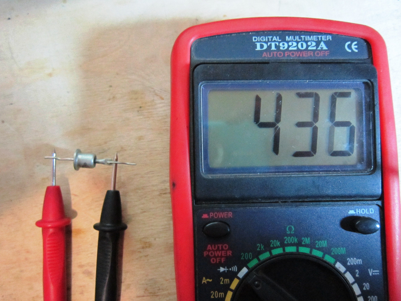
As we can see, the multimeter showed a voltage of 436 millivolts. This means that the end of the diode that touches the red probe is the anode, and the other end is the cathode. 436 millivolts is the voltage drop across the forward junction of the diode. According to my observations, this voltage can be from 400 to 700 millivolts for silicon diodes, and for germanium diodes from 200 to 400 millivolts.

One on the multimeter means that now electricity does not flow through the diode. Therefore, our diode is quite working.
How to test an LED with a multimeter
But how to check the LED? Yes, just like the diode! The whole point is that if we stand with a red probe on the anode, and black on the cathode of the LED, it will glow!

Look, it glows a little! This means that the output of the LED, on which the red probe is the anode, and the output on which the black probe is the cathode. The multimeter showed a voltage drop of 1130 millivolts. For LEDs, this is considered normal. It can also vary, depending on the "model" of the LED.
We change the probes in places. The LED did not light up.

We pass the verdict - a fully functional LED!
But how to check diode assemblies and diode bridges? Diode assemblies and diode bridges are a connection of several diodes, mainly 4 or 6. We find the circuit diode assembly or bridge and check each diode individually. How to check the zener diode, read the article.