A weak WiFi signal is an urgent problem for residents of apartments, country houses and office workers. Dead zones in the WiFi network are characteristic of both large rooms and small-sized apartments, the area of which is theoretically capable of covering even a budget access point.
The range of a WiFi router is a characteristic that manufacturers cannot clearly indicate on the box: the WiFi range is affected by many factors that depend not only on the technical specifications of the device.
This material presents 10 practical tips to help eliminate the physical causes of poor coverage and optimize the range of a WiFi router, it's easy to do it yourself.
The radiation of the access point in space is not a sphere, but a donut-shaped toroidal field. For WiFi coverage within one floor to be optimal, radio waves must propagate horizontally - parallel to the floor. For this, there is the possibility of tilting the antennas.

The antenna is the "donut" axis. The angle of propagation of the signal depends on its slope.

When the antenna is tilted relative to the horizon, part of the radiation is directed outside the room: dead zones are formed under the plane of the "donut".

A vertically installed antenna radiates horizontally: indoors, maximum coverage is achieved.
On practice: Placing the antenna vertically is the easiest way to optimize your indoor WiFi coverage.
Place the router closer to the center of the room
Another reason for the occurrence of dead zones is the poor location of the access point. The antenna emits radio waves in all directions. In this case, the radiation intensity is maximum near the router and decreases as it approaches the edge of the coverage area. If you install the access point in the center of the house, then the signal is distributed among the rooms more efficiently.
A router installed in a corner gives off some of the power outside the house, and distant rooms are at the edge of the coverage area.

Mounting in the center of the house allows for an even distribution of signal in all rooms and minimizes dead zones.
In practice: Installing an access point in the “center” of the house is far from always feasible due to complex layouts, lack of sockets in the right place, or the need to lay a cable.
Provide line of sight between the router and clients
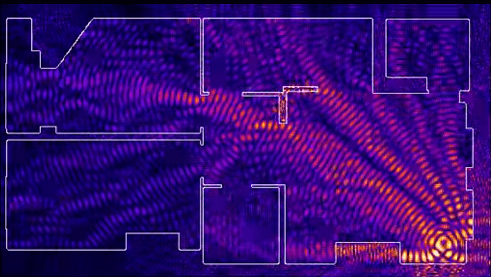
WiFi signal frequency is 2.4 GHz. These are decimeter radio waves that poorly bend around obstacles and have low penetrating power. Therefore, the range and stability of the signal directly depend on the number and structure of obstacles between the access point and clients.
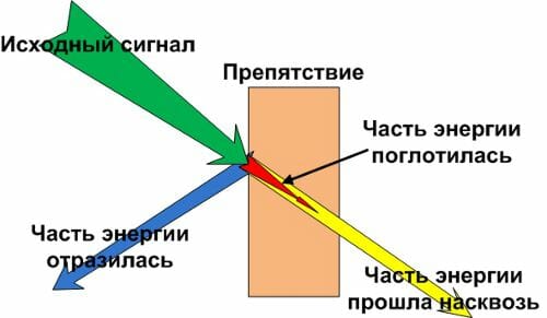
Passing through a wall or ceiling, an electromagnetic wave loses some of its energy.
The amount of signal attenuation depends on the material that the radio waves travel through.


* Effective distance is a value that determines how the radius of a wireless network changes compared to an open area when a wave passes an obstacle.
Calculation example: A WiFi 802.11n signal propagates in line-of-sight conditions over 400 meters. After overcoming the non-capital wall between the rooms, the signal strength decreases to 400 m * 15% = 60 m.The second wall of the same kind will make the signal even weaker: 60 m * 15% = 9 m.The third wall makes signal reception almost impossible: 9 m * 15 % = 1.35 m.
Such calculations will help to calculate the dead zones that arise from the absorption of radio waves by walls.
The next problem in the path of radio waves: mirrors and metal structures. Unlike walls, they do not attenuate, but reflect the signal, scattering it in arbitrary directions.
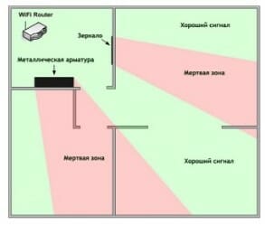
Mirrors and metal structures reflect and scatter the signal, creating dead zones behind them.

If you move the elements of the interior that reflect the signal, it will be possible to eliminate the dead zones.
In practice: It is extremely rare to achieve ideal conditions when all gadgets are in direct line of sight with a router. Therefore, in a real home, you will have to work separately to eliminate each dead zone:
- find out what interferes with the signal (absorption or reflection);
- think over where to move the router (or piece of furniture).
Place the router away from sources of interference
The 2.4 GHz band does not require licensing and therefore is used for the operation of consumer radio standards: WiFi and Bluetooth. Despite its low bandwidth, Bluetooth can still interfere with the router.
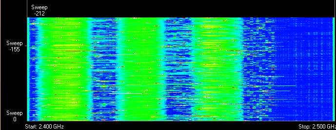
Green areas - stream from WiFi router. Red dots are Bluetooth data. The proximity of two radio standards in the same range causes interference, which reduces the range of the wireless network.
The magnetron of the microwave oven emits in the same frequency range. The radiation intensity of this device is so great that even through the protective screen of the oven, the radiation of the magnetron is able to “light up” the radio beam of the WiFi router.

Microwave oven magnetron radiation causes interference on almost all WiFi channels.
On practice :
- When using Bluetooth accessories near the router, turn on the AFH parameter in the settings of the latter.
- The microwave is a powerful source of interference, but it is not used as often. Therefore, if it is not possible to move the router, then it will simply not be possible to make a Skype call while preparing breakfast.
Disable support for 802.11 b / g modes
WiFi devices of three specifications work in the 2.4 GHz band: 802.11 b / g / n. N is the latest standard and offers greater speed and range than B and G.

The 802.11n (2.4 GHz) specification provides longer range than the legacy B and G standards.
802.11n routers support previous WiFi standards, but the mechanics of backward compatibility are such that when a B / G device, such as an old phone or a neighbor's router, appears in the N router's area, the entire network is switched to B / G mode. Physically, the modulation algorithm changes, which leads to a drop in the speed and range of the router.
In practice: Putting the router in “pure 802.11n” mode will definitely have a positive effect on the quality of the coverage and throughput of the wireless network.
However, B / G devices will not be able to connect via WiFi. If it's a laptop or TV, they can be easily connected to the router via Ethernet.
Choose the optimal WiFi channel in the settings
Almost every apartment today has a WiFi router, so the density of networks in the city is very high. Signals from neighboring access points overlap each other, draining energy from the radio path and greatly reducing its efficiency.
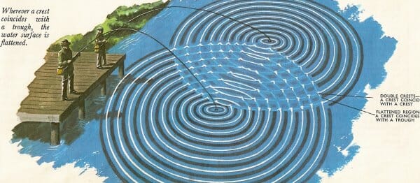
Neighboring networks operating at the same frequency create mutual interference interference, like circles on water.
Wireless networks operate within range on different channels. There are 13 such channels (in Russia) and the router switches between them automatically.

To minimize interference, you need to understand which channels the neighboring networks operate on and switch to a less loaded one.
Detailed instructions for setting up a channel are presented.

In practice: Selecting the least congested channel is an effective way to expand the coverage area, which is relevant for residents of an apartment building.
But in some cases, there are so many networks on the air that not a single channel gives a tangible increase in the speed and range of WiFi. Then it makes sense to turn to method number 2 and place the router away from the walls bordering neighboring apartments. If this does not work, then you should think about switching to the 5 GHz range (method no. 10).
Adjust the transmitter power of the router
The transmitter power determines the energy of the radio path and directly affects the range of the access point: the more powerful the beam, the further it hits. But this principle is useless in the case of omnidirectional antennas of household routers: in wireless transmission, two-way data exchange occurs and not only clients must “hear” the router, but vice versa.
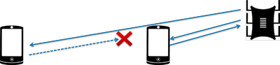
Asymmetry: the router “reaches out” to a mobile device in the back room, but does not receive a response from it due to the low power of the smartphone's WiFi module. The connection is not established.
In practice: The recommended value for the transmitter power is 75%. It should be increased only in extreme cases: the power turned 100% not only does not improve the signal quality in distant rooms, but even worsens the stability of reception near the router, since its powerful radio stream “clogs” the weak response signal from the smartphone.
Replace the original antenna with a more powerful one
Most routers are equipped with standard antennas with a gain of 2 - 3 dBi. The antenna is a passive element of the radio system and is not able to increase the flow power. However, increasing the gain allows the radio signal to be refocused by changing the directional pattern.
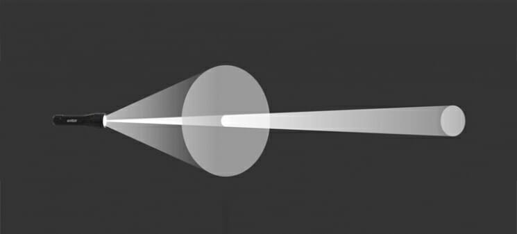
The higher the antenna gain, the further the radio signal propagates. In this case, the narrower stream becomes similar not to a “donut”, but to a flat disc.

There is a large selection of antennas for routers with a universal SMA connector on the market.


In practice: Using an antenna with a high gain is an effective way to expand the coverage area, because simultaneously with the signal amplification, the antenna sensitivity increases, which means the router begins to “hear” remote devices. But due to the narrowing of the radio beam from the antenna, dead zones arise near the floor and ceiling.
Use signal repeaters
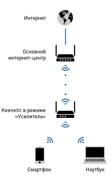
In rooms with complex layouts and multi-storey buildings, it is effective to use repeaters - devices that repeat the signal of the main router.


The simplest solution is to use an old router as a repeater. The disadvantage of this scheme is half the throughput of the child network, since along with the client data, the WDS access point aggregates the upstream from the upstream router.
Detailed instructions for configuring the WDS bridge are presented.
Specialized repeaters are free from the problem of bandwidth cuts and are equipped with additional functionality. For example, some models of Asus repeaters support the roaming function.

In practice: No matter how complicated the layout is, repeaters will help you deploy a WiFi network. But any repeater is a source of interference. With free air, repeaters do their job well, but with a high density of neighboring networks, the use of repeater equipment in the 2.4 GHz band is impractical.
Use 5 GHz band
Budget WiFi devices operate at 2.4GHz, so the 5GHz band is relatively free and has little interference.

5 GHz is a promising range. It works with gigabit streams and has an increased capacity compared to 2.4 GHz.
In practice: “Moving” to a new frequency is a radical option that requires the purchase of an expensive dual-band router and imposes restrictions on client devices: only the latest models of gadgets work in the 5 GHz band.
The problem with the quality of the WiFi signal is not always related to the actual range of the access point, and its solution in general terms boils down to two scenarios:
- In a country house, it is most often required, in free air conditions, to cover an area that exceeds the effective range of the router.
- For a city apartment, the range of a router is usually sufficient, and the main difficulty lies in eliminating dead zones and interference interference.
The methods presented in this material will help to identify the causes of poor reception and optimize the wireless network without resorting to replacing the router or the services of paid specialists.
Found a typo? Select the text and press Ctrl + Enter
A weak WiFi signal is an urgent problem for residents of apartments, country houses and office workers. Dead zones in the WiFi network are characteristic of both large rooms and small-sized apartments, the area of which is theoretically capable of covering even a budget access point.
The range of a WiFi router is a characteristic that manufacturers cannot clearly indicate on the box: the WiFi range is affected by many factors that depend not only on the technical specifications of the device.
This material presents 10 practical tips to help eliminate the physical causes of poor coverage and optimize the range of a WiFi router, it's easy to do it yourself.
The radiation of the access point in space is not a sphere, but a donut-shaped toroidal field. For WiFi coverage within one floor to be optimal, radio waves must propagate horizontally - parallel to the floor. For this, there is the possibility of tilting the antennas.
The antenna is the "donut" axis. The angle of propagation of the signal depends on its slope.
When the antenna is tilted relative to the horizon, part of the radiation is directed outside the room: dead zones are formed under the plane of the "donut".
A vertically installed antenna radiates horizontally: indoors, maximum coverage is achieved.
On practice: Placing the antenna vertically is the easiest way to optimize your indoor WiFi coverage.
Place the router closer to the center of the room
Another reason for the occurrence of dead zones is the poor location of the access point. The antenna emits radio waves in all directions. In this case, the radiation intensity is maximum near the router and decreases as it approaches the edge of the coverage area. If you install the access point in the center of the house, then the signal is distributed among the rooms more efficiently.
A router installed in a corner gives off some of the power outside the house, and distant rooms are at the edge of the coverage area.
Mounting in the center of the house allows for an even distribution of signal in all rooms and minimizes dead zones.
In practice: Installing an access point in the “center” of the house is far from always feasible due to complex layouts, lack of sockets in the right place, or the need to lay a cable.
Provide line of sight between the router and clients
WiFi signal frequency is 2.4 GHz. These are decimeter radio waves that poorly bend around obstacles and have low penetrating power. Therefore, the range and stability of the signal directly depend on the number and structure of obstacles between the access point and clients.
Passing through a wall or ceiling, an electromagnetic wave loses some of its energy.
The amount of signal attenuation depends on the material that the radio waves travel through.
* Effective distance is a value that determines how the radius of a wireless network changes compared to an open area when a wave passes an obstacle.
Calculation example: A WiFi 802.11n signal propagates in line-of-sight conditions over 400 meters. After overcoming the non-capital wall between the rooms, the signal strength decreases to 400 m * 15% = 60 m.The second wall of the same kind will make the signal even weaker: 60 m * 15% = 9 m.The third wall makes signal reception almost impossible: 9 m * 15 % = 1.35 m.
Such calculations will help to calculate the dead zones that arise from the absorption of radio waves by walls.
The next problem in the path of radio waves: mirrors and metal structures. Unlike walls, they do not attenuate, but reflect the signal, scattering it in arbitrary directions.
Mirrors and metal structures reflect and scatter the signal, creating dead zones behind them.
If you move the elements of the interior that reflect the signal, it will be possible to eliminate the dead zones.
In practice: It is extremely rare to achieve ideal conditions when all gadgets are in direct line of sight with a router. Therefore, in a real home, you will have to work separately to eliminate each dead zone:
- find out what interferes with the signal (absorption or reflection);
- think over where to move the router (or piece of furniture).
Place the router away from sources of interference
The 2.4 GHz band does not require licensing and therefore is used for the operation of consumer radio standards: WiFi and Bluetooth. Despite its low bandwidth, Bluetooth can still interfere with the router.
Green areas - stream from WiFi router. Red dots are Bluetooth data. The proximity of two radio standards in the same range causes interference, which reduces the range of the wireless network.
The magnetron of the microwave oven emits in the same frequency range. The radiation intensity of this device is so great that even through the protective screen of the oven, the radiation of the magnetron is able to “light up” the radio beam of the WiFi router.
Microwave oven magnetron radiation causes interference on almost all WiFi channels.
On practice :
- When using Bluetooth accessories near the router, turn on the AFH parameter in the settings of the latter.
- The microwave is a powerful source of interference, but it is not used as often. Therefore, if it is not possible to move the router, then it will simply not be possible to make a Skype call while preparing breakfast.
Disable support for 802.11 b / g modes
WiFi devices of three specifications work in the 2.4 GHz band: 802.11 b / g / n. N is the latest standard and offers greater speed and range than B and G.
The 802.11n (2.4 GHz) specification provides longer range than the legacy B and G standards.
802.11n routers support previous WiFi standards, but the mechanics of backward compatibility are such that when a B / G device, such as an old phone or a neighbor's router, appears in the N router's area, the entire network is switched to B / G mode. Physically, the modulation algorithm changes, which leads to a drop in the speed and range of the router.
In practice: Putting the router in “pure 802.11n” mode will definitely have a positive effect on the quality of the coverage and throughput of the wireless network.
However, B / G devices will not be able to connect via WiFi. If it's a laptop or TV, they can be easily connected to the router via Ethernet.
Choose the optimal WiFi channel in the settings
Almost every apartment today has a WiFi router, so the density of networks in the city is very high. Signals from neighboring access points overlap each other, draining energy from the radio path and greatly reducing its efficiency.
Neighboring networks operating at the same frequency create mutual interference interference, like circles on water.
Wireless networks operate within range on different channels. There are 13 such channels (in Russia) and the router switches between them automatically.
To minimize interference, you need to understand which channels the neighboring networks operate on and switch to a less loaded one.
Detailed instructions for setting up a channel are presented.
In practice: Selecting the least congested channel is an effective way to expand the coverage area, which is relevant for residents of an apartment building.
But in some cases, there are so many networks on the air that not a single channel gives a tangible increase in the speed and range of WiFi. Then it makes sense to turn to method number 2 and place the router away from the walls bordering neighboring apartments. If this does not work, then you should think about switching to the 5 GHz range (method no. 10).
Adjust the transmitter power of the router
The transmitter power determines the energy of the radio path and directly affects the range of the access point: the more powerful the beam, the further it hits. But this principle is useless in the case of omnidirectional antennas of household routers: in wireless transmission, two-way data exchange occurs and not only clients must “hear” the router, but vice versa.
Asymmetry: the router “reaches out” to a mobile device in the back room, but does not receive a response from it due to the low power of the smartphone's WiFi module. The connection is not established.
In practice: The recommended value for the transmitter power is 75%. It should be increased only in extreme cases: the power turned 100% not only does not improve the signal quality in distant rooms, but even worsens the stability of reception near the router, since its powerful radio stream “clogs” the weak response signal from the smartphone.
Replace the original antenna with a more powerful one
Most routers are equipped with standard antennas with a gain of 2 - 3 dBi. The antenna is a passive element of the radio system and is not able to increase the flow power. However, increasing the gain allows the radio signal to be refocused by changing the directional pattern.
The higher the antenna gain, the further the radio signal propagates. In this case, the narrower stream becomes similar not to a “donut”, but to a flat disc.
There is a large selection of antennas for routers with a universal SMA connector on the market.
In practice: Using an antenna with a high gain is an effective way to expand the coverage area, because simultaneously with the signal amplification, the antenna sensitivity increases, which means the router begins to “hear” remote devices. But due to the narrowing of the radio beam from the antenna, dead zones arise near the floor and ceiling.
Use signal repeaters
In rooms with complex layouts and multi-storey buildings, it is effective to use repeaters - devices that repeat the signal of the main router.
The simplest solution is to use an old router as a repeater. The disadvantage of this scheme is half the throughput of the child network, since along with the client data, the WDS access point aggregates the upstream from the upstream router.
Detailed instructions for configuring the WDS bridge are presented.
Specialized repeaters are free from the problem of bandwidth cuts and are equipped with additional functionality. For example, some models of Asus repeaters support the roaming function.
In practice: No matter how complicated the layout is, repeaters will help you deploy a WiFi network. But any repeater is a source of interference. With free air, repeaters do their job well, but with a high density of neighboring networks, the use of repeater equipment in the 2.4 GHz band is impractical.
Use 5 GHz band
Budget WiFi devices operate at 2.4GHz, so the 5GHz band is relatively free and has little interference.
5 GHz is a promising range. It works with gigabit streams and has an increased capacity compared to 2.4 GHz.
In practice: “Moving” to a new frequency is a radical option that requires the purchase of an expensive dual-band router and imposes restrictions on client devices: only the latest models of gadgets work in the 5 GHz band.
The problem with the quality of the WiFi signal is not always related to the actual range of the access point, and its solution in general terms boils down to two scenarios:
- In a country house, it is most often required, in free air conditions, to cover an area that exceeds the effective range of the router.
- For a city apartment, the range of a router is usually sufficient, and the main difficulty lies in eliminating dead zones and interference interference.
The methods presented in this material will help to identify the causes of poor reception and optimize the wireless network without resorting to replacing the router or the services of paid specialists.
Found a typo? Select the text and press Ctrl + Enter
The article will discuss how to calculate the range of propagation of a Wi-Fi radio signal indoors without using any software in principle. Explains in detail what a RF propagation model is and how to use it to calculate RF propagation range.
Introduction
Sometimes it is necessary to at least roughly estimate the range of operation of wireless equipment. This assessment may be required both at home, when you need to understand where the boundary of your access point lies, and in the case of designing a small office network, when the almighty system administrator must tell the boss how many devices may be required to have Wi everywhere in the office. -Fi ".
Everything seems to be simple, you need to calculate how far the signal (electromagnetic wave) will fly from the antenna of the access point. But a distinctive feature of calculating the attenuation of an electromagnetic wave in free space from attenuation in a cable is that the cable, as a rule, is well shielded, and third-party objects can appear in free space, or it itself (space) from time to time can change its electrophysical properties. In addition, due to interference and diffraction of radio waves, the direction of propagation of an electromagnetic wave and its energy reserve can change many times, both in the smaller and in the larger direction on the path of the wave from the transmitter to the receiver.
In the event that it is necessary to determine the signal attenuation inside the cable assembly, then it is often enough to know the specific attenuation of the cable and the losses on its (cable) connectors. Thus, the formula for calculating the total attenuation in this case may look quite simple:
where: P to - attenuation on the connector (s);
Р n - linear attenuation in the cable;
L is the cable length.
If free space is considered, then it is extremely problematic to predict what level of the electromagnetic signal from the Wi-Fi access point will be at the location of the subscriber. In modern realities, before designing a Wi-Fi network, its planned electromagnetic map is built using various software and hardware systems. The software packages include: TamoGraphSiteSurvey, AirMagnet Survey / Planner, Site Survey and Planning Tool from Ekahau, etc. For example, the figure below shows the appearance of a project in one of the listed programs.

These programs are based on a mathematical core built on the basis of so-called radio signal propagation models (radio signal loss models). Some of them also use more complex electrodynamic models.
Models for calculating the loss of Wi-Fi radio signal
Models for calculating radio signal losses allow us to estimate the attenuation of an electromagnetic wave emitted by a Wi-Fi adapter, taking into account the number and type of obstacles in the signal path. This article discusses signal propagation models used to calculate the signal level inside buildings. There are a lot of models, which will be discussed, and their modifications. The article discusses the most simple ones that can be used even in the field without deep mathematical knowledge.
Before starting to consider various models of radio signal propagation, we note that under ideal conditions (there are no obstacles in the signal path, and there are no multiple signal reflections), the signal power at any point in free space (FS) can be estimated using the so-called Friis formula:

where: - transmitter antenna gain;
- receiver antenna gain;
- wavelength, meters;
- distance between receiver and transmitter, meters.
Figure 1 shows a graph of the dependence of the attenuation L FS with increasing distance for a Wi-Fi signal on the first frequency channel (central frequency 2437 MHz) in the 2.4 GHz band - the blue curve, and in the 5 GHz band - the red curve. In this case, the gains of the receiving and transmitting antennas were taken equal to unity.

Figure 1 - Attenuation of the Wi-Fi signal with increasing distances
As a rule, most propagation models use the free space loss value as a base value, and add variables to it that introduce additional attenuation depending on the type of obstacles and their electrophysical properties. Such models include, for example, One slope and Log-distance. In addition, there is a loss model standardized by the International Telecommunication Union - ITU-R 1238. The listed loss models belong to the class of empirical static models, that is, to use them, you need a general description of the type of problem (type of room). The listed loss models with decoding of the variables included in them are given in formulas (3 - 5).

where: d is the distance in meters at which the attenuation is assessed;
Lfs- losses at a distance of d0 meters;
n is a coefficient depending on the number and material of obstacles.

where: is a normal random variable, measured in dB, with a standard deviation, dB.

where: d> 1, m is the distance at which the attenuation is assessed;
f is the frequency of the central Wi-Fi channel, MHz;
N is the coefficient of signal level loss with distance;
Lf (n) - coefficient of signal power loss when passing through a wall (floor);
- the number of walls (floors) between the receiving and transmitting antennas.
In the future, we will consider the ITU-R 1238 model in more detail, apply it to determine the communication range, and compare the calculation results with the experimental results. The values in the higher formulas taken by the variables N, n are described in detail directly in the recommendation ITU-R P. 1238-5 under the title "Data on propagation of radio waves and prediction methods for planning indoor radio communication systems and local area radio networks in the frequency range 900 MHz - 100 GHz "(volume - 19 pages). For the experiment that will be carried out below, the values of the variables will be selected from the indicated recommendation. In different situations, variables can take on different values, and in order to list all possible cases, you would have to place at least 10 document pages out of 19 in the article.
Unfortunately, the listed models do not take into account the influence on the access point (more precisely, on the electromagnetic wave emitted by it) of third-party equipment operating in the same frequency range. Therefore, all calculations are made on the basis that your device is the only one in the entire range of its (equipment) action. As the practice of calculations shows, if there are 20-30 wireless devices within the hearing range of your access point, then the range is reduced by 15-20%. But it should be borne in mind that this figure is purely approximate and in different situations it can manifest itself in different ways, because it very much depends on the power of the signal that comes to your device, and on what frequency the surrounding equipment is operating at.
Comparison of experimental results with the ITU-R 1238 model
Problem statement: the installed Wi-Fi access point operates in the 5 GHz frequency range. The receiving device (laptop) is installed at six points, the schematic arrangement of which is shown in Figure 2, and registers the radiated power. The choice of the location of the measurement points was made in such a way as to minimize the influence of the multipath effect on the received signal level. It is assumed that the maxima of the receiving and transmitting antenna patterns are directed towards each other.

Figure 2 - Comments on the task
Before starting the calculations, it should be noted that the authors of the ITU-R 1238 model made it very flexible, in particular, due to the fact that the input coefficient N can vary in wide ranges: from 20 to 40 dB. To understand what value to equate N for a particular situation, it is better to refer directly to the original source of the recommendation.
For the considered range, the signal power loss factor when passing through the walls for our type of problem - L fn is calculated by the formula L fn = 15 = 4 (n-1) Thus, for points 1-3 L f (n) = 15. for points 4-6 Lf (n) = 19 (Table 3 of Recommendation ITU-R P. 1238-5). The factor N used in calculating the transmission loss indoors is assumed to be 30 (Table 2 of Recommendation ITU-R P. 1238-5). Taking into account the chosen geometry of the problem, fading will not be taken into account.
The results of calculations at 6 points according to the ITU-R formula are summarized in Table 1, and the distances to each measurement point from the Wi-Fi router are shown in Figure 3.

Figure 3 - Distances from the access point to the measurement point
Table 1

The results obtained are shown in Figure 4 for a more visual presentation.

Figure 4 - Results of calculations and measurements
The smallest difference between the experimental and calculated data is observed at measurement points 1 and 4. This is due to the fact that the signal passes through obstacles (in this case, walls) along the shortest path. Conversely, at points 2,3 and 5,6 the signal loses b O Most of the energy is passing through obstacles along a longer path. This effect is not taken into account in the used signal propagation model, which leads to an increase in the difference between the calculated and experimental data.
Conclusion
Thus, in this work, a practical example was shown of the application of a standardized model for calculating the attenuation of a Wi-Fi signal inside a building. This and other models will help you rather quickly, without the use of specialized software, estimate the amount of equipment required for your office. Of course, this approach will not replace high-quality design calculations in specialized software products, but it will allow what is called "navigating the terrain", you just need to take into account the geometry of the building to obtain more correct results.
How to increase the range of your WiFi router? No one likes it when web pages open too slowly, streaming media cannot be broadcast, and WiFi signal periodically drops out or forms dead zones. Such problems simply drive people crazy all over the world, where a stable Internet has become as much a necessity as a person's primary needs. The simple tips below can help you strengthen your WiFi signal.
Possible signal barriers
The most obvious problem is the distance between the computer and the router, since there is an optimal range within which a wireless signal can travel. If, according to the user's idea, the network should cover a larger area than the router can technically cover, or WiFi has to bypass corners and penetrate walls, then the signal quality may suffer greatly or it will not reach its goal at all.
Interference from other users is also a big problem, especially in densely populated areas. Signals from other wireless networks and electronics can negatively affect speed and distance. Telephone systems and other wireless devices cause interference. Fortunately, there are already dedicated home telephones using the DECT 6.0 standard, which does not interfere with Wi-Fi.
There is always a chance that uninvited guests can connect to the router signal. It makes sense to periodically log into your router's admin interface to check how many devices are currently connected. Or use a network analyzer to see if there are unknown devices on the network. You should not use an open network, you should always close it. It is best to use WPA2 security settings because WEP is significantly weaker. It is imperative that you come up with a complex password that cannot be guessed.

Improving signal quality and distance
You can increase the signal range by updating the software for your router. Router manufacturers usually strive to improve their products and release useful enhancements to them. The firmware update process may differ depending on the router model. Most routers (for example, the well-known TP-Link) have an update process built right into the administration interface. As a result, all user intervention is reduced to a banal clicking on the "Refresh" button. Some older models may require the user to independently find the firmware on the developer's website and install it. This is rather inconvenient, but necessary.
Much will depend on where the router is located. As you know, not all rooms and open spaces are the same in terms of volume, structure and presence of obstacles. Many users try to move the router further away (for example, in a closet or on a windowsill). But this approach is wrong, because the router needs open spaces. It should be kept away from obstacles.
If the router is equipped with external antennas, make sure they are in an upright position. If possible, move the router higher, for example, hang it on a wall. If this cannot be done on your own, then it is recommended to put it on a high cabinet or at least on a table. There are special programs that can visualize the coverage area. Examples include Heatmapper or inSSIDer. These programs will show the user the strengths and weaknesses of the WiFi network. There are also similar applications for mobile devices such as WiFi Analytics.
How to understand how far does the wifi router work? How far should it work stably? Why isn't it catching in my room?
Are very frequently asked questions. Indeed, you can often find that the range of a stable WiFi signal is annoyingly small. Should it be so? Maybe this is okay? Let's figure it out.
For industrial WiFi hotspots such distances as the limits of an apartment or a standard summer cottage on 10 acres is not a problem... However, the use of such devices requires permission from the frequency supervision. Without such permission, only Wi-Fi routers and access points of the consumer segment of the wireless device market are available to you. They are at least two times weaker than their industrial counterparts, which affects the range and quality of communication.
Most common home routers and access points are equipped with antennas up to 5dB and a transmitter with a power of up to 100 mW. These are restrictions for WiFi use in residential areas. It is not recommended to bypass sanitary standards of this kind. But there are ways, and they are described in the article.
Also in the given article you can find the rules for the location of the router for more efficient work.
So how far does a WiFi router work!
In an open field with a reduced level of radio interference, the signal of a good home router can be caught, and at a distance of 100 meters... Agree, not bad.
But in urban conditions, sometimes even the highest-quality representatives of the segment cannot cope with the transmission of a high-quality signal to the next room. It is sad.
Usually single antenna range router does not exceed 10m in a straight line in a city. Two and three-antenna routers can extend even longer distances due to better signal filtering.
The presence of obstacles significantly reduces the distance supported by the router. Sometimes, the signal is absent already at arm's length, if something is shielding the signal, for example, a mirror, refrigerator or metal mesh.
Conclusions:
- If your single antenna keeps communication at a distance of more than 10m, you are very lucky.
- If the situation is completely sad, then read the article WiFi Connection Difficulties. Stable signal.
- If this does not help, then we carry the router for repair or buy a new one. In the absence of a guarantee, it is more profitable to buy a new one.
I hope the material helped you. If you have any questions. Feel free to ask them in the form below the article itself. The author tries to promptly answer visitors' questions, usually within two days. Also, by checking the box next to the "Notify", under the comment form, you can receive an answer to the mail.


