How to make an antenna for a TV with your own hands, so that it is not inferior in quality to a purchased device, this question interests many home craftsmen and TV enthusiasts. There are various ways to make an antenna yourself, from the simplest designs to devices that receive a satellite signal.
This option is suitable for people who want to install a conventional indoor antenna at home or in the country to view federal channels. Everyone can design such a device, special knowledge is not required.
This is the most elementary way, so you only need copper wire 70–90 cm, 2–3 mm thick. An indoor antenna is made as follows:
- Strip both ends of the copper wire.
- Attach one end to the battery, and insert the other into the TV connector.
The signal will appear immediately, from 1 to 5 channels will become available to the user. With this simple method, you can make a home antenna in 5 minutes.
The most popular way to make an antenna with your own hands from improvised materials. For the manufacture will need beer cans. Experts say that in order to assemble an antenna from beer cans, it will take no more than an hour.
You will need:
- Connecting cable.
- Several cans of beer.
- Plug.
- Screws in the amount of 2 pieces.
- Screwdrivers.
- Insulating tape or heat shrink tubing.
- Wooden beam or metal pipe for mounting the antenna.
You can make a homemade antenna from tin cans according to the following scheme:

This is another easy option on how to make a TV antenna in a short time. The device picks up the signal well, providing high quality images.
All-wave antenna with amplifier
An all-wave antenna with an amplifier can be of different configurations. Its assembly takes more time than the first two options. But the advantage is that it is very powerful, and receives all analog channels in excellent quality. One of the common options is an all-wave antenna of the “BUTTERFLY” shape.
Tools:
- Board or plywood sheet, dimensions 550/70/5 mm.
- Copper wire.
- Connecting cable PK75.
- Drill.
- Soldering iron.
- Plug.

Instruction:

Do-it-yourself TV antenna is ready to go.
decimeter antenna
Homemade antennas that pick up a decimeter signal can be of various configurations.
Option 1
The simplest option is it is relatively easy and simple to assemble.
You will need:
- Plywood.
- Cord.
- Soldering iron.

Instruction:
- Make a ring out of the connecting cable, size 53 cm.
- Cut another piece of cable to make a loop, size 17.5 cm.
- You need to solder a loop to the ring, and a cable that will be inserted into the screen.
- Attach the structure to the plywood.
- Direct the assembled device towards the TV tower.
Thus, the UHF band antenna is assembled with your own hands.
Option 2
Another possible method for making a TV antenna UHF range called "Eight".
Tools:
- Wire (copper, aluminum).
- Glue gun.
- Cable.
- Wire cutters.
Instruction:

This is another way to make an antenna yourself.
This instrument has a signal range reach up to 490 MHz, which means that the picture quality will be very high. But for the manufacture you need to purchase a transformer.
You will need:
- Transformer.
- Foil.
- Glue.
- Roulette.
- Cardboard.
- stapler.
- Marker.

Instruction:
The device is ready to work.
DIY satellite dish
One of the most popular questions is, is it possible to make a satellite dish with your own hands? There are many videos on the Internet on how to make a dish for watching satellite TV yourself.
This device can be made at home in two ways:
- Sticker on the matrix.
- Solder mesh and wire.
The first method of manufacture is considered the most optimal and convenient. To do this, you need to make a drawing of the future device. This stage of work must be approached very responsibly, all parameters must be calculated accurately, otherwise the output will be an unusable device. A parabola is drawn in the drawing, which is then transferred to a steel sheet. Its thickness should be 0.05 cm.

Stages of work
- Using a welding machine, make a steel frame with a diameter of 9–10 cm. The steel bars are turned out to the outside, and the bearing is welded to the center.
- Install the resulting structure on level ground, and a pipe is attached to the installed bearing, then a knife is installed.
- Then the frame is poured with concrete mortar and dried for 5 days.
At the final stage, it is necessary to glue the antenna, this can be done in different ways. For ease of use, it is recommended divide the structure into 8 parts. For gluing, fiberglass or epoxy primer is used.
Apply machine oil to the dried concrete form, insert the pipe into the washer. After that, the homemade plate is covered with resin and the fiberglass is glued. The manufacturing process of the device is completed. Read also.
10.10. UHF Antennas
In the AMV range, due to a decrease in the effective length of the receiving antenna, with increasing frequency, a lower voltage develops at the antenna input than under the same conditions in the meter range. Therefore, it becomes necessary to install antennas with a high gain. In antennas of the "Wave channel" type, this is achieved by increasing the number of directors, creating in-phase arrays from multi-element antennas (Fig. 10.30). Since the dimensions of the antenna elements of adjacent channels differ slightly, they are usually given for a group of channels (Table 10.20).
Table 10.20
13-element antenna type "Wave channel" consists of three reflectors, an active loop vibrator and 9 directors. The distance between the ends of the loop vibrator A is 10...20 mm. The diameter of the antenna vibrators is 4...8 mm. The antenna gain is 11.5 dB, the opening angle of the main lobe of the radiation pattern in the horizontal and vertical planes is 40°.
19-element wave channel antenna for the UHF range (Fig. 10.31) consists of three reflectors, an active loop vibrator and 15 directors. The vibrators are made of wire and tubes with a diameter of 4 mm. They are attached in any way to the carrier boom with a diameter of 20 mm. The boom length for any channel group is 2145 mm (Table 10.21). The antenna gain is 14...15 dB, the opening angle of the main lobe of the radiation pattern in the horizontal and vertical planes is 30...32.
Broadband antenna of the "Wave channel" type for reception in channels 21 ... 41(Fig. 10.32).
Depending on the distance to the television transmitter and the zone of reliable reception of its signals, the number of elements (directors) of the antenna can be reduced to 8.11 or 15.
In the case when preference is given to reception in one television channel (for example, reception of an NTV program from Kolodishchi), the dimensions of the antenna elements and the distances between them can be recalculated for this channel.
Table 10.21
The UHF broadband antenna has the highest gain (13 dB) in the 28th channel, the average frequency of which is 500 MHz. The conversion factor (Kp) in this case is determined by the formula
Kp=530/fcp
where fcp is the average frequency of the UHF channel, MHz. For the 37th channel, the average frequency of which is 562 MHz, Kp is equal to:
Kp=530/562=0.943.
Multiplying the dimensions of the elements and the distance between them by 0.943, we obtain the dimensions of the antenna for the 37th channel (Fig. 10.33). You can also recalculate a broadband antenna for any channel (or group of channels) of the UHF. The average frequency of the channel (group of channels) is given in Table. 10.2, the length of the half-wave loop - in table. 10.1. When using a metal carrier boom (traverse), the dimensions of the elements obtained during recalculation are increased by half of its diameter.
The gain of the channel antenna increases to 14...15 dB. An antenna of eight elements is used at a distance of up to 20 ... 30 km from the village. Kolodishchi, from 11 - up to 30 ... 40, from 15 elements - up to 50 ... 60 km. Behind the zone of reliable reception at a distance of up to 70 ... 90 km, an antenna of 24 elements is used. To ensure good quality of the received image, an antenna amplifier is installed directly on the mast.
The antenna is little influenced by nearby objects and has good repeatability. Deviations of up to 2 mm from the calculated dimensions are permissible with virtually no deterioration in the antenna parameters.
Antenna type "Wave channel" with a complex passive reflector(Fig. 10.34; tables 10.22 ... 10.24) consists of a lattice reflector (Fig. 10.35, a), two sheets of which are installed at an angle of 90 ° at the end of the carrying boom, an active loop vibrator (Fig. 10.35, b) and 18 directors.
At the same time, the first two directors (A1 and D2) are two-story and spaced vertically by the thickness of the carrier boom (Table 10.23).
Table 10.22
The main advantage of such an antenna is the reliable screening of the rear hemisphere due to the increase in the coefficient of protection when installing a complex reflector. The latter concentrates the energy of the useful signal in the direction of the active vibrator, which helps to increase the gain of the antenna.
Table 10.23
Table 10.24
On fig. 10.36 shows a side view of the antenna described above. The 6-element antenna is designed for short-range reception at a distance of up to 10 ... 15 km from a television transmitter:
10-element - 15...25; 15-element - 25...40; 20-element - at a distance of 40 ... 60 km or more.
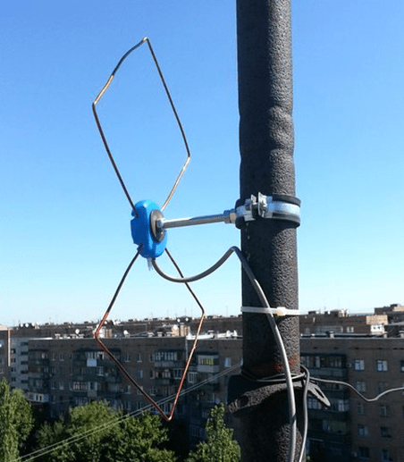
In the UHF range are widely used loop Antenna Triple Square, the frames of which are made of a single piece of copper, brass wire with a diameter of 2 ... 3 mm. With the dimensions of the decimeter range (Table 10.25), the antenna has sufficient rigidity. The wire must be bent in a certain way (Fig. 10.37). At points A, B and C, the wires must be stripped and soldered. In this design, instead of a loop (see Fig. 10.12), made from a piece of coaxial cable, a quarter-wave short is used.
a closed bridge (see Fig. 10.11) of the same length as the loop (see Table 10.5). The distance between the bridge wires remains the same (30 mm). The design of such an antenna is quite rigid, and the lower boom is not needed here.
The feeder is tied to the right wire of the bridge from the outside. When the feeder approaches the vibrator frame, the cable braid is soldered to point X "the central conductor is to point X. The left wire of the bridge is fixed on a dielectric stand or, in the case of an external antenna, on a mast. It is important that there is no feeder and mast stand in the space between the wires of the bridge .
In the presence of copper, brass or aluminum strips
can be done diamond-shaped antenna(Fig. 10.38). The strips (1) are overlapped with screws and nuts. There must be reliable electrical contact at the point of contact between the plates. The thickness of the strips is arbitrary.
A diamond-shaped antenna can operate in the frequency band of channels 21 ... 60, its gain is 6 ... 8 dB. To increase it, the antenna can be equipped with a reflector (Fig. 10.39).
The simplest reflector is a flat screen made of tubes or pieces of thick wire. The diameter of the reflector elements is not critical (3...10 mm). The reflector sheet (2) is fixed with the support stands (3)
Table 10.25
to a metal or wooden mast (4). Points 0 have zero potential, relative to the ground, so the posts (2) can be metal.
Feeder (5) - a RK type cable with a wave impedance of 75 Ohm is laid to power points A and B. The cable braid is soldered to point B, and the central conductor to point A. At long-range reception, the diamond-shaped antenna can be equipped with a broadband amplifier (6).
2-element Swiss antenna(see Fig. 10.21) can also be used in the UHF range (Table 10.26).
Modernization of the "Polish" antenna under T2
You can use the "Polish" antenna as a whole assembly with an amplifier without alteration, but as experience shows, some frequency channels have a weak signal level.
Here we are all surprised at the versatility of the "Polish" antenna, and the Polish antenna is nothing more than the simplest combination of the simplest universal "butterfly" antenna widely known since the 60s with a vibrator length of 1150 mm and an opening angle of 38 ° for reception from 1 to 12 th channel in line of sight conditions
and a primitively designed "wave channel antenna" and not a single size fits into any calculations and GOSTs. That is, we have a conventional, practically, dummy UHF antenna in a "Polish" antenna for receiving UHF (I'm talking about directors-passive selectors). It turns out that only a "butterfly" works in this antenna, or rather several "butterflies" are active selectors, and I also note those designed for a certain range (they are all the same length), and an SWA amplifier.
If you remove the SWA amplifier, then the antenna will not work. I lead to what it is enough to bend such an active vibrator of a certain size (we will talk about this below), connect the SWA amplifier. get much better "Polish"
ATTENTION: the cable is routed along the arm of the active vibrator, which is connected to the “case” of the amplifier circuit! At the midpoint of the vibrator, where the RF potential is equal to zero, the cable is smoothly bent and directed along the traverse, then - to decrease.
In short, any homemade antenna + SWA amplifier works much better than any "Polish".
But what we already have is what we have. Let's try to bring it a little into a normal DMV look. "Meter" mustaches (long active vibrators, see fig. 1) are absolutely not needed, if we use an antenna for T2 (UHF wave range), you can cut them to the same length with decimeter active vibrators. If one of the received channels is weaker than the others, it is necessary to try to remove the reflector sheet from the active vibrators. With this adjustment of the antenna, its output impedance increases and the frequency response changes. Changing the antenna impedance does no harm at all, since the input impedance of the amplifier is higher than the antenna impedance. Radio amateurs with experience with antenna amplifiers can solder matching-balancing elements on a ferrite ring from the amplifier circuit, this will expand the range of operation of the active antenna. One of the input terminals of the antenna is connected to the input of the amplifier, and the second - to the "case" of the amplifier circuit.
Antenna resistance at equal received power is related to the output voltage
P=U2/R. U=(P*R)½.
From this follows the conclusion - it is necessary to increase the output impedance of the antenna (the input impedance of the amplifier is greater than the resistance of the antenna). With success, you can use antennas with an impedance above 300 ohms. This connection method is also suitable for a wide-range antenna of the "wave channel" type (more on this later), and in a log-periodic antenna, the output cable is symmetric, passing through the antenna element (according to the principle of Fig. 2).
Something I have a lot of abstruse quirks, you still think that I'm smart already .... yes, no, everything is simple - Would you google with mine
I'll try to keep it simple
I do not advise cutting "long mustaches" if you do it for yourself, if you are lazy or for "uncle" I advise you to shorten it with the calculation L (vibrator length) = 1/2j (half the average length of a weak frequency channel)
And for ourselves, we bend two rhombuses and remove the reflector from the back of the rhombuses, or insert the bushing into the mount and bend it 10 cm
Now let's conjure with the directors. I already mentioned the "wave channel" antenna, this is a miracle known from the time of black and white TV
So let's take the dimensions of the directors and the distances between them with the "grandfather" antenna tested over the years.
vibrator no. length in mm distance in mm
7…………………………..107...............0
6…………………………..129..............80
5…………………………..155..............94
4…………………………..186..............77
3…………………………..225..............63
2…………………………..272..............53
1…………………………..330...............43
0....................................... ...........35
Do-it-yourself high-quality MV-UHF antenna "wave channel"
This type of antenna belongs to purposeful UHF antennas.
Since the gain of the purposeful UHF antenna is better than that of the Polish array, it was decided to make a "hybrid" from the old domestic UHF antenna and the ASP-8 Polish array with its amplifier. Happened! The image quality of the weak improved markedly. The idea of \u200b\u200bmanufacturing was proposed somewhere by someone, it only remained to implement it.
I will tell simply, without any abstruse expressions and formulas.
For self-manufacturing of the antenna, it took:
Special program for calculating Antwu15;
1 or 2 amplifiers from the grid (with cases);
Aluminum pipe section? o 25mm and length? 2m. (traverse);
3 aluminum tubes with a cross section of up to o10mm, two lengths of? 1m. (MV) and more? 2.5-3m. (for cutting UHF elements);
2 sheets of textolite 3-5 mm thick, dimensions: 300mmx150mm (for mounting MV);
You will also need self-tapping screws (? 20 pcs. 15 mm) and bolts with nuts (thread x3 6 pcs. 20 mm) (for fastening DMV and MV elements);
Attention Critical here is the distance from the active vibrator "two rhombuses" or "butterfly" (cut off long mustaches) as someone did, also for other "butterflies" to the first director (unless of course there is a desire to change wires (tubes), here segments from long mustache
The last figure shows the dimensions and distances for channel frequencies in the band 21 ... 41. For the remaining frequency channels, the dimensions can be calculated using the Antwu15 () program
So, let's start with the program. With its help, you can calculate various options for antennas tuned to different ranges. We launch. We are only interested in the first point.
Everything is simple. We enter the data for which the antenna will be tuned, and the program will do everything itself.
For example:
The center frequency of the antenna refers to the broadcast frequency of the last 61-69 channels. The number of elements determines the length of the traverse. We set the diameter of the elements 1-5 (not so significant).
The method of fastening the elements is through the traverse. We agree, and as a result we get the finished dimensions for our product.
Below is the result obtained, according to which one of the variants of the UHF antenna was made. This option provides a stable reception of a signal from a tower 80 km away through splitters for two TVs and a PCI-TV tuner in a computer.
It remains only to collect. The length of the antenna is determined by the number of elements
I advise you to put directors for one frequency range on each "butterfly" (they will all be the same length) - four "butterflies" correspond to four frequency channels of Ukraine
Here is another table of director lengths for a universal log-periodic antenna (counting from the "butterfly") from 21 .... 64
How to use the program we discussed above
We get the dimensions calculated by the program. It remains only to assemble. The length of the antenna is determined by the number of elements, you can calculate 1.4m, but the gain will be less. In general, the choice is yours.
To obtain better shielding from the reflected signal, the role of a reflector can be performed by a grating-screen from the ASP-8 "Polish" antenna, dimensions: long - as in the calculation of the program, height 300 mm. Curved edges point forward. You can also use other material in the form of sheet iron, aluminum, or use old UHF antennas.
Now we are preparing an MV antenna from two meter vibrators. It's much easier here. Its role will be played by 2 tubes with a cross section of 10 mm and a length of 1 m, folded at an unfinished angle of 120 degrees. This part of the antenna can not be assembled if we collect strictly meter waves for T2. And what do we have for the antenna?
Here is a sketch of the resulting "monster":
Well, back to my "sheep" - we'll finish assembling the antenna.
Next we take the traverse. We make its length 5 cm longer for mounting the MV antenna. The traverse is an aluminum tube with a sec. 25mm. and make notches on it at the points of attachment of the elements, the loop vibrator and the reflector. Distance, according to the calculated table. We drill 10mm holes through them at a right angle, and insert elements into them. You can fasten the elements in different ways: with self-tapping screws from above, by cutting threads in the elements with bolts, or by putting rubber tubes on the elements, firmly insert them into the holes of the traverse.
The heart of the antenna is a loop vibrator, which can be made from a 13mm wide aluminum plate, or a 10mm aluminum or copper tube.
The size of the loop vibrator is selected empirically, already on the assembled antenna.
The loop is not needed, instead we use an amplifier from the "Polish" antenna. We fasten its body with bolts into the holes of the vibrator.
Attention And now we are furnishing the “crow”, we don’t put a long mustache - this is a meter-long part of the antenna, we put a reflector from the “Polish woman” and bend it in this way like a UHF antenna with a complex reflector
We fasten the antenna to the mast well, install the mast - preferably higher, direct it and the "crow" is resting. Good luck
Do-it-yourself simple UHF TV antenna
1. Ring-coaxial cable PK75, 530mm long.
2. Loop-coaxial cable PK75, 175mm long.
3. To the console.
Assembly:
To assemble this antenna, you do not even have to run around the shops.
To do this, you need to take the PK75 antenna cable 530mm long (for the ring) and 175mm. (for loop).
Connect as shown in the figure.
Fasten to a sheet of plywood (plexiglass) using wire ties.
Direct to telecentre.
Here you have a UHF antenna that will work no worse than a purchased one.
And if you still go to the market or to the store, buy an SWA amplifier (we put the SWA amplifier instead of a loop) and a power supply unit for it (40 UAH), then it’s even better to buy it.
Do-it-yourself television antenna DMV "Narodnaya"
The antenna is an aluminum disk with an outer diameter of 356mm and an inner diameter of 170mm. and 1mm thick., in which a 10mm wide cut was made.
A printed circuit board made of fiberglass 1 mm thick is installed in place of the cut. This board has two holes for fixing with M3 screws.
The terminals of the matching transformer T1 are soldered to the printed circuit board attached to the antenna.
For a transformer, it is best to use a ring core with an outer diameter of 6 ... 10 mm., An inner diameter of 3 ... 7 mm. and 2…3 mm thick.
The transformer windings are superimposed with a single-layer insulated wire with a diameter of 0.2 ... 0.25 mm. and have the same number of turns, from 2 to 3 turns. The length of the turns of the turns is 20mm.
In the presence of such a transformer, reception is possible in the meter and decimeter range at a distance of 25 ... 30 km. At a distance of up to 50 km. the antenna works satisfactorily only on UHF channels.
Without a transformer, the reliable reception distance is halved.
However, there is a circuit that allows you to get similar results without a transformer, for this you need to assemble the following circuit:
Here you can also use an SWA amplifier (we put an SWA amplifier instead of a transformer) and a power supply unit to it. But as experience shows, it is better to use a transformer to which we supply power to the power supply unit from the "Polish"
UHF television antenna with a simple do-it-yourself reflector
Taking this antenna as a basis, I bent a big mustache on the "Polish"
1. aluminum strip frame
2.amplifier
3. mast
4. reflector
A. Braid Solder Point
B. central conductor soldering point
Assembly:
1. First, a frame is assembled from aluminum plates, overlapping, as shown in the figure, with the help of bolts (after fastening, the fastening points should be painted with paint to avoid oxidation).
2. Further, a coaxial cable is soldered at points A and B.
3. bolt the frame to the mast
4. make from rods with a diameter of 3 ... 10 mm. (Or you can just a reflector from a collapsed polish or fittings for wall ticking), attaching the reflector to the mast with brackets
5. fix the amplifier on the mast, bring the coaxial cable to it.
Assembly is possible without a reflector, however, the gain of such an antenna will be lower.
Do-it-yourself television antenna UHF with a complex reflector
1. a frame made of aluminum strips (a reflector from a collapsed polish or fittings for wall ticking)
2.amplifier
3. mast
4. reflector
Assembly:
1. First of all, a frame is assembled, from aluminum plates, as for a simple reflector
2. Next, a reflector of the "dilapidated box" type is assembled as shown in the figure (The design of such a reflector can be very different, it all depends on your capabilities).
3. the reflector is attached to the mast on metal brackets
3. then the amplifier is attached to the mast, and the coaxial cable is soldered, too, as with a simple reflector
On decimeter waves in the range of 470-638 MHz (channels 21-41), directional antennas can be used as indoor antennas, since their dimensions on these waves are relatively small. As directional indoor antennas of decimeter waves, antennas of the “wave channel” type are most convenient.
Figure 1 shows the external view of the indoor decimeter wave antenna ATCD-2 of the "wave channel" type, operating without tuning on channels from 21 to 41 in the range of 470-638 MHz. The geometric dimensions of the antenna are shown in Fig. 2a. The antenna consists of a base with a stand and a removable antenna sheet. The antenna sheet contains an active vibrator 1, a reflector 2 and two directors 3 and 4, which are made of brass or steel tape and attached to a plastic boom.
Drop cable 5 is connected to the antenna through a short-circuited balancing bridge (Fig. 2b), the length of which is equal to a quarter of the wavelength at the middle frequency of the 470-638 MHz range. The bridge is formed by a two-wire line, one conductor of which is the metal screen of the drop cable, the second is section 6 of the MGShV mounting wire with a cross section of 0.35 mm2. At a distance of 140 mm from the antenna input terminals, equal to the required length of the bridge (a quarter of a wavelength at a frequency of 550 MHz), the mounting wire is soldered to the cable shield. The gain relative to the half-wave vibrator is not less than 5.5 dB.
Here is another version of the bending of the "long mustache" of the Polish antenna and the replacement of directors (for the range of 42 ... 64 length and distance we calculate the program)
Do-it-yourself television log-periodic antenna of the UHF range
To make a web, the tubes of two hoops should be unbent, and then bent according to the given template and both halves of fig.
On the tubes at the bends, notches should first be made (after about 200 mm). The antenna can be attached to the mast with getinax plates or wooden blocks (three are enough). The cable is laid along the canvas in accordance with the upper figure.
To protect against corrosion, the places of soldering and the joints of the strips with the canvas are smeared several times with BF glue (such protection is enough for several years). The braid must be soldered to the strip of that half of the antenna along which the cable is laid. To get the maximum signal, you need to add a reflector from metal strips (screw directly to the mast with screws). The distance between the antenna web and the reflector is selected according to the best image (110 ... 160 mm). The dimensions are given in accordance with the setting for the 30th channel fig.
Well, if there is no desire to steam, we make a transformer as in the "folk" or put an SWA amplifier.
However, due to the wide band, the antenna receives signals well in the range from the 21st to the 40th channel. Such an antenna, even without a reflector, gave better results than a 16-element wave channel, all other things being equal. As you can see, this antenna is more powerful for the "butterfly" and "wave channel" and, as I said in the "Polish" antenna of the director, this is a dummy, that's we throw out all the "butterflies" and from an aluminum wire with a diameter of 6 mm we bend two halves of semi-diamonds according to the template, inserting them into the mounts instead of butterflies. Well, we move the reflector to the desired distance (here's another option for upgrading the "Polish")
Added after 53 minutes 13 seconds:
Do-it-yourself universal car television antenna
All-wave car television antenna with a circular radiation pattern in the horizontal plane. This antenna can also be used in stationary conditions, i.e. not only on a car, but also for home TV. You can also take the modernization of the "Polish" antenna as a basis - bend the "long mustache" with a ring of a certain diameter, or rather bend it like this, connecting with a neighbor's butterfly - this is one mustache, and the second bend as in Indoor antenna decimeter waves "wave channel" active loop vibrator for example (I remind you, we take the size of 1/2 wavelength of a poorly showing range)
car television antenna consists of
1. 2 aluminum rings (d=270mm and d=130mm)
2. wooden rail (3x3cm.)
3. TV cable
Assembling a car television antenna
Such an antenna can be built using a commercially available 300/75 ohm plug (see figure) with a matching transformer inside it for imported TVs.
Two aluminum rings are attached to the plug using the screws on it: one with a diameter of 270 mm for the MV band (channels 6-12), the other with a diameter of 130 mm for the UHF band (channels 23-51). Since the MV ring does not suit us (we need a channel range of another 51 ... 64), we change it to a calculated diameter of 90 mm. The antenna made in this way is attached to a wooden rail with a section of 3x3 cm with a hole for the plug plug. The plug is attached to the rail with electrical tape, and the rings are fastened with two insulators to stiffen the system. The rail is bolted to the trunk frame located on the roof of the car. Using a typical industrial cable (plug-socket) RK-75-4-11, the antenna is connected in the rear of the car to the car TV.
The antenna can be equipped with an amplifier (SWA-7 or SWA-9) powered by the vehicle battery to increase efficiency.
Do-it-yourself universal "can" television antenna of the UHF range
The proposed antenna uses improvised materials. But, nevertheless, it works in the entire range of TV UHF, and is not inferior in terms of parameters to a standard six-element log-periodic antenna, which is commercially available.
To make this antenna, you will need two empty cans with a diameter of 7.5 cm, a length of 9.5 cm and two small strips of filtered fiberglass.
The cans are connected with strips of fiberglass using soldering. The upper strip is solid, and the foil on the bottom is cut, (as shown in the figure)
for connecting a 75-ohm power cable.
The total length of the antenna for operation in all UHF channels must be at least 25 cm.
This antenna is something like a symmetrical broadband vibrator. Due to the large surface area, it has a high gain. When using cans of small diameter, it is necessary to cut the foil in the upper strip.
Added after 16 minutes 44 seconds:
Do-it-yourself frame television antenna UHF range
This antenna has a high gain and can be used both indoors and outdoors. Differs in ease of manufacture, availability of materials, small size, aesthetic appearance.
The design of the antenna is shown in the figure, the dimensions are in the table:
Based on a three-loop antenna. For the manufacture of the antenna, any wire made of copper, brass, steel, aluminum, etc. with a diameter of 3 ... 8 mm is taken and bent according to the pattern. At the joints, the wires are soldered. The antenna cable is soldered to points A and B. At point C, the cable sheath is connected to the antenna material.
It is possible to take this antenna as the basis for the modernization of the "Polish" antenna - bending a long mustache in the form of an average square, taking into account that B (Polish) \u003d 1 / 2B (frame)
Currently in Moscow DVB-T2 digital broadcasting is carried out on the following channels: 30 (multiplex 1), 24 (multiplex 2) , 34 (multiplex 3. It is in testing mode, some TV channels have not been finally determined) UHF band (see frequency grid).
Since January 2015, the third multiplex has been switched on in Moscow and the Moscow region(!) on channel 34, whose programs are now selected by tender. Permanent programs of the 3 multiplex are: Match! Arena, Music of the First and life news. You can see the list of programs that participate in the tender.
(!) On channel 58 (770 MHz) since October 2016, a test broadcast of an ultra-high-definition signal (Ultra HD 4K) has been conducted. The signal can be received by any resident of Moscow and the nearest suburbs if there is a TV with Ultra HD/DVB-T2/HEVC support.
| Multiplex 1 | Multiplex 2 | Multiplex 3 | ||
| channel 30 (546 MHz) | channel 24 (498 MHz) | channel 34 (578 MHz) | ||
| Programs | Programs | Programs | ||
| 1 channel | Ren TV | Match! Arena | ||
| Russia 1 | Saved | My Planet, Science 2.0 Fight club |
||
| Match! | STS | History, Cartoon, Russian detective, Russian bestseller |
||
| NTV | Home | Country, Sundress | ||
| 5 (Peter) | TV 3 | Mom, 24_DOC, Amusement park IQ HD |
||
| Russia K | Friday | Euronews, Trust | ||
| Russia 24 | Star | Music of the First | ||
| Carousel | World | La Minor, Kitchen TV, Auto plus, India TV; HD Life, STV |
||
| OTR | TNT | lifenews | ||
| TVC | Muz TV | Our football (temporarily coded) |
You can choose the receiver type.
A device for the most accurate tuning of digital terrestrial (DVB-T/T2) antennas.
Long Range DVB-T2 Antennas
DVB-T2 Balcony Antennas
| AURA | ||
 |
Compact antenna for receiving television signals in the UHF range with a built-in LTE filter(above 790 MHz). Helps to avoid the negative impact of interference from LTE / 4G cellular networks on receiving equipment and provide a more uniform frequency response in the UHF operating band. Horizontal polarization. Minimum packaging volume and easy assembly without tools. It is widely used for installation on a balcony in apartments for broadcasting digital terrestrial television of the DVB-T2 standard. | |
| Price: 29 € | ||
 |
Small Antenna with Built-in Amplifier +5 V. Designed to receive television signals in the UHF range. It is easy to install on the wall (using a bracket) or directly on the balcony grille in apartments for broadcasting digital terrestrial television of the DVB-T2 standard. |
T2 digital television is actively entering our lives. To date, antennas have already been installed in many homes to receive such a signal. But what about those who live in the suburbs or in a rented apartment? The solution is quite simple - this is a homemade antenna for T2, which can be an inexpensive and reliable alternative to a factory product.
Do-it-yourself TV antennas
In order to catch digital terrestrial television, first of all, you need to have a supporting new digital format TV, and then you do not have to buy a special set-top box.
In addition, an indoor or outdoor decimeter antenna is required. Do not believe those who say that the device must be digital or something else. Quite simply, a do-it-yourself TV antenna can be made from improvised materials, resulting in a powerful device that will perfectly receive the signal.
A simple do-it-yourself decimeter antenna
Before preparing materials for the manufacture of the device, it is necessary to calculate its future length. To do this, you need to find out the frequency at which digital broadcasting takes place, and apply a special formula: divide 7500 by the frequency in megahertz and round the result.
A decimeter antenna for TV is made from a conventional 75-ohm television coaxial cable and standard connector.
After all the correct actions, the search for channels will begin. If the repeater is located in an area up to fifteen kilometers from home, then the signal will be received well and an amplifier will not be required. If the distance is greater, then the use of an amplifier is necessary.
Do-it-yourself digital antenna "eight"
In order for the signal quality to be exactly good, you can make a more complex home-made television antenna for TV.
To make it, you will need to prepare:
- television cable;
- box;
- roulette;
- foil;
- glue;
- scotch.
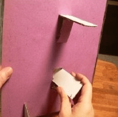
The bottom of the box (for example, from under shoes) will need to be well smeared with glue and completely covered with foil. In this case, it is necessary to ensure that the foil does not rise anywhere.
While the foil is sticking, you need to cut two pieces of 50 centimeters each from the cable, and strip the ends of the insulation by carefully cutting off the outer sheath with a knife. Having bent the braid to the side at all ends, bend the segments into a circle so that they do not close completely. The distance between them should be approximately 1 centimeter.
Secure the resulting figure eight with tape to the lid of the box. In this case, it is necessary to ensure that the stripped ends are located next to each other. The cable on the box should hold well, so there is no need to spare the adhesive tape. The antenna frame is ready.
Now follows prepare the main cable that will connect to the TV.

It remains only to mount the connector for the TV. To do this, at the remaining end of the television cable, you need to remove the insulation, wring out and cut off the braid, remove the foil. Then, stepping back from the braid half a centimeter, remove the inner insulation of the core.
The TV connector must be screwed onto the prepared cable so that the core with insulation is not visible in the wide part. After that, from the edge of the connector, step back half a centimeter and bite off the excess part of the core, put on the second part of the connector and screw it on.
The cable and antenna are ready. Having installed the device in a convenient place, it must be directed towards the TV transmitter, connect the cable and turn on the TV. The antenna should work well, and the TV should show without interference.
Homemade antenna from cans
An antenna that will catch not one or two channels, but as many as seven or eight can be made from the simplest tin cans. To make it, you will need to prepare:

First of all, it should prepare the cable, removing the top layer from it in a segment of 10 centimeters from the beginning. The wiring inside the cable must be untwisted, the foil removed from under them, cut off one centimeter of the stripped layer. Put a plug on the other end of the wire.
Now follows prepare banks. Attach the core of the cable to the rings of one of them, and part of the untangled wires to the other. If there are no rings, then you can screw self-tapping screws into the jars and wind the wires on them, treating the surface with a soldering iron.
After that, the jars need with the help of adhesive tape attach to hanger. The distance between them should be 75 millimeters, the banks should be placed in one straight line.
Homemade television antenna is ready. Now you need to connect it to the TV with a plug and find a place for it where the signal will be best caught.
Indoor antenna for TV "Rhombus"
 This design is a diamond-shaped frame, it is made quickly and easily, and digital television signals are received confidently and easily. For her, you will need to prepare a copper or aluminum rod about 180 centimeters long.
Rhombus should get two. One will act as a reflector, and the second as a vibrator. The side of the frame should be about 14 centimeters, and the distance between them should be about 10 centimeters.
After the rhombus is made, between the two ends of the rod it is necessary to install a dielectric. Its size and shape can be arbitrary. The main thing is to make sure that the distance between the bars is about two centimeters.
Now the upper parts of the frames need to be connected, and a cable is connected to the copper or brass petals attached to the antenna output.
If the repeater is located far away or with the help of the resulting device a weak signal quality will be caught, then it will be possible to add amplifier. The result will be an active decimeter antenna for TV, which can be used not only in the city, but also in the country.
Of course, such devices for receiving a television signal will not have an exquisite design, but with their help you can enjoy your favorite programs.


