The modern market offers a huge range of antennas for receiving terrestrial television. There are two main types of these products, allowing the reception of the meter and decimeter range of radio air. They can also be divided according to the place of use into outdoor and indoor. Basically, they are not much different. Here, first of all, emphasis is placed on the size and preservation of the necessary parameters under the influence of weather conditions. In this article we will discuss the existing types of these products, consider what parameters they have, how to conduct testing. And for those who like to craft, we will tell you how a decimeter antenna is made with their own hands.
What's the difference?
Let's try to explain in a nutshell how to determine what kind of product is in front of you. The decimeter range antenna looks like a ladder. Install them parallel to the ground. Meters are crossed aluminum tubes. The appearance of both types is shown in the photo below. There are also combined antennas, when both the "ladder" and the cross tubes are combined.
Problem of choice
It would seem that everything is simple. However, in this case, the buyer faces the question of how to choose the right device, what parameters to pay attention to. In general, it is best to test TV antennas directly in the conditions in which they have to work. The passage of a radio signal is often individual for a particular area. So, the product in laboratory conditions shows some results, and in the "field" - completely different. There is a certain tactic that allows you to test both meter and decimeter TV antennas. However, choosing such a product in a store, we are not able to conduct a full test. No vendor would be willing to give us several different antennas to test. In this case, you have to rely on the characteristics of these products. And hope that the selected antenna will perform its functions according to passport data, and not real conditions.

Main settings
The decimeter antenna is characterized primarily by the directional pattern. The main parameters of this characteristic are the level of the side (auxiliary) lobes and the width of the main lobe. The width of the chart is determined in the horizontal and vertical planes at the level of 0.707 from the largest value. So, according to this parameter (the width of the main lobe), the diagrams are usually divided into non-directional and directional. What does this mean? If the main lobe is narrow, then the antenna (decimeter) is directional. The next important parameter is noise immunity. This characteristic primarily depends on the level of the back and side lobes of the diagram. It is determined by the ratio of the allocated antenna power under the condition of a matched load at the moment of receiving a signal from the main direction to the power (with the same load) when receiving from the lateral and rear directions. First of all, the shape of the diagram depends on the number of directors and the design of the antenna.
What does the term “wave channel” mean?
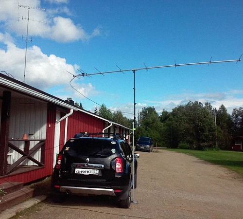
TV antennas of this type are very effective directional receivers of radio signals. They are widely used in areas of clearly weak television coverage. Antenna (decimeter) of the "wave channel" type has high gain and has good directivity. In addition, these products are relatively small in size, which (along with the high level of amplification) makes it very popular among residents of summer cottages and other settlements far from the center. This antenna also has a second name - Uda-Yagi (named after the Japanese inventors who patented this device).

Principle of operation
Antenna decimeter type "wave channel" is a set of elements: passive (reflector) and active (vibrator), as well as several directors, which are installed on a common boom. Its principle of operation is as follows. The vibrator has a certain length, it is in the electromagnetic field of the radio signal and resonates at the frequency of the received signal. In it, an electromagnetic field is induced on each passive element, which also leads to the emergence of an EMF. As a result, they re-emit secondary electromagnetic fields. In turn, these fields induce an additional EMF on the vibrator. Therefore, the dimensions of the passive elements, as well as their distances to the active vibrator, are chosen such that the EMF induced by them due to the secondary fields is in phase with the main EMF, which is induced in it by the primary electromagnetic field. In this case, all EMFs are summed up, which provides an increase in the efficiency of the structure in comparison with a single vibrator. Thus, even an ordinary room can provide stable signal reception.
The reflector (passive element) is installed behind the vibrator 0.15-0.2 λ 0. Its length should exceed the length of the active element by 5-15 percent. This antenna produces a one-way directional pattern in the vertical and horizontal planes. As a result, the reception of reflected signals and fields that come from the back of the antenna is significantly reduced. If it is necessary to receive a television signal at long distances, as well as in difficult conditions, in the presence of a large amount of interference, it is recommended to use a three- or more element antenna, which consists of an active vibrator, one or more directors and a reflector.

Direct and reflected signals
In an article devoted to a wave receiving device (Tele-Sputnik No. 11, 1998), it was noted that in the case when the signal source is not a standard (that is, not a laboratory) generator and a radiating antenna, and the signal is broadcast by a television tower, a significant the weather conditions play a role, as well as the location of the receiver. This especially affects the operation of products in the UHF range. This is explained by the fact that in the decimeter range it is less, respectively, the avoidance of obstacles is much worse, and any signal reflections play an important role in the quality of the received picture. In particular, even the wall of a house can be a wave reflector. So, in the absence of line of sight, this property can be used - to receive the reflected signal. However, its quality will be lower than that of the direct one. If the level of the transmitted signal is high, but there is no line of sight, then you can use the reflected wave. In fact, an indoor decimeter antenna works exactly on this principle. Indeed, it is difficult to catch a direct wave in a room if the windows face the opposite direction. Therefore, if you try, you can always find a point where the received signal will be higher. But in the case of line of sight, any reflected interference will spoil the received picture.
A technique for comparing antenna parameters
In order to test receiving devices, they need to create the same conditions:
1. Choose an installation location in which your antenna will work. You can use a balcony, roof or mast. The main thing is that both the height and the place are the same for all products.
2. The direction to the source of the broadcast signal should be maintained with an accuracy of three degrees. To do this, you can make a special mark on the attachment pipe.
3. Measurements should be carried out under the same weather conditions.
4. The cable between the antenna and the TV must have the same impedance and length. It is best to use one wire, changing only the receivers.
Testing should only be performed on products of one type. For example, an indoor UHF antenna should not be compared with an outdoor or meter receivers. It should be understood that field testing may produce results that differ materially from laboratory testing.

Decimeter antenna for digital television
Recently, the mass media have been talking more and more insistently about the need to switch to digital television. Many have already done this, and someone else is thinking. So far, the signal is broadcast in both modes. However, the quality is poor. In this regard, people are interested in what decimeter antennas can be used for T2. Let's deal with this issue. In fact, digital television broadcasts on the UHF-band channel. So a standard UHF antenna may be suitable for receiving it. Receivers can often be seen in stores that say they are for digital television. However, this is a marketing ploy to sell a standard decimeter antenna for more than it costs. Buying such a product, you will not have a guarantee that it will provide a better reception than what is already in your home and has been working for more than one year. As we said earlier, the quality depends mainly on the level of the transmitted signal and line-of-sight conditions. However, it should be borne in mind that in most cities much more powerful generators are used for the transmission of digital television than for analogue. This is done in order to accelerate the transition to the new standard. After all, viewers want to see a clear image, not "snow" on the screens. Therefore, if a receiver is displayed in the window, on which is written "Decimeter antenna for DVB T2", you should know: this does not mean that there is some special product in front of you. It's just that a not entirely honest seller wants to cash in on an uninformed buyer. You should also be aware that the program for the transition to the new standard provides for the creation of advisory centers. In them you can get comprehensive information on any issue related to digital television. All consultations are free of charge. In some cities, this equipment is in test mode, so the signal may be unstable or weakened. Do not worry, the center staff will always advise you on how to solve the problem with the signal reception quality.

DIY decimeter antenna
The length of the UHF waves falls within the interval from 10 cm to 1 m. From this feature, their name comes from. at this frequency they propagate mainly in a straight line. They practically do not bend around obstacles, only partially reflected by the troposphere. In this regard, long-distance communication in the decimeter range is very difficult. Its radius does not exceed one hundred kilometers. Let's look at a couple of examples of how to make a decimeter antenna at home.
The first version of a homemade television broadcast receiver will, so to speak, be assembled on a knee from scrap materials. UHF channels are located in the range from 300 MHz to 3 GHz. Our task is to make an antenna that will work exactly at these frequencies. For this we need two 0.5 liter beer cans. If you use a container with a larger volume, then the received frequency will decrease. For installation, you will need some kind of frame, you can use a board 10 cm wide. You can also use an ordinary wooden hanger, in which case the resulting antenna can be hung on a nail in any convenient place in the room. In addition to the frame and cans, it is necessary to prepare a couple of self-tapping screws, tools, coaxial cable, connector, terminals, insulating tape. We put on the TV connector on one end of the cable and solder it. We put the other end into the terminal block. Next, we attach the terminals with screws to the necks of the cans. The wires should fit snugly against the metal. Now let's start assembling the antenna itself. To do this, we fix the cans with their necks facing towards the horizontal bar. The distance between them should be 75 mm. You can use insulating tape to secure the cans. That's it, the antenna is ready! Now it is necessary to find a place of stable reception of a television signal and hang our "hanger" in this place.

Receiver for digital television
This section is intended for people who do not want to use a conventional (analog) product, but want a dedicated decimeter antenna for the new format. With your own hands, such a receiving device is also easy to assemble. To do this, we need a square wooden (can be made of plexiglass) frame with a diagonal of 200 mm and a regular cable RK-75. The variant presented to your attention is a zigzag antenna. It has proven itself to be excellent when working in the range of digital television reception. Moreover, it can be used in places where there is no line of sight to the signal source. If you have a weak broadcast, you can connect an amplifier to it. So let's get to work. We strip the end of the cable by 20 mm. Next, we bend the wire in the shape of a square with a diagonal of 175 mm. We bend the end outward at an angle of 45 degrees, the second cleaned end is bent to it. We connect the screens tightly. The stripped central core hangs freely in the air. At the opposite corner of the square, carefully remove the insulation and the screen in an area of 200 mm. This will be the top of our antenna. Now we connect the resulting square with a wooden frame. At the bottom, where the two ends are connected, copper staples made from thick wire should be used. This will provide better electrical contact. That's all, the decimeter antenna for digital television is ready. If it will be installed outside, you can make a plastic case for it, which will protect the device from precipitation.
K. Kharchenko
Reception of television transmissions at radio frequencies 470 ... 622 MHz (21-39 channels) of the decimeter wave range (DCW) requires an appropriate approach to the calculation and design of antenna devices.
Some radio amateurs are trying to solve this problem by a simple recalculation, based on the principles of electrodynamic similarity of antennas, the parameters of the existing designs of meter-band television antennas (1-12 channels). At the same time, they inevitably face the difficulties of the recalculation itself and often do not get the desired results.
What are the basic principles of approach to solving this problem?
In free space, radio waves emitted by the antenna have a spherical divergence, as a result of which the electric field strength E decreases in inverse proportion to the distance r from the antenna.

Under real conditions, propagating radio waves undergo greater attenuation than existing in free space. To take into account this attenuation, the attenuation factor F (r) = E / Ebw is introduced, which characterizes the ratio of the field strength for real conditions to the field strength of free space at equal distances, identical antennas and powers supplied to them, etc. Using the attenuation factor the field strength produced by the transmitting antenna under real conditions at a distance r can be expressed as
The receiving antenna converts the energy of the electromagnetic wave into an electrical signal. Quantitatively, this antenna ability is characterized by its effective area Seff. It corresponds to that area of the wave front, from which all the energy contained in it is absorbed, with the directive pressure, this area is related by the ratio:

The foregoing makes it possible to write the equation of radio transmission, which links the parameters of the communication equipment (transmitter and receiver) and antennas and determines the signal level on the path: with the transmitter power P1, the signal power P2 at the receiver input will be equal to

The parenthesized multiplier in this expression defines the basic propagation loss (basic transmission loss). In this case, it is assumed that the antenna is matched with the feeder, and the feeder with the television receiver and, in addition, the antenna is matched in polarization with the signal field.
Let us consider expression (11) in more detail.

This particular example shows that with an increase in the frequency (decrease in the wavelength) of television transmissions, the power of the signal entering the input of the television, all other things being equal, decreases rapidly, that is, the reception conditions deteriorate. On the transmission side, they try to compensate for these troubles by increasing the product P1V1. But in real conditions, the factor F (r) and the efficiency of the receiving feeder decrease with increasing frequency, so the need to increase the gain of the receiving antenna Y2 becomes inevitable. This conclusion entails another one, which is that, as a rule, for reliable reception of programs of 21-39 television channels, it is necessary to use new, more directional antennas compared to antennas used in the wavelength range of 1-5 channels.
In an effort to obtain stable reception of television broadcasts, radio amateurs are forced to complicate antennas, for example, to build antenna arrays, that is, they combine several antennas of the same type, proven in practice (each of which has its own pair of power points) with a common power system and only one (common for all) by a couple of food points. At the same time, they often underestimate the importance of the matching stage in the construction of antenna arrays associated with relatively complex measurements. Let us illustrate what has been said with such a concrete example.

A similar effect is obtained when three elements are connected in parallel (Fig. 1, c). Continuing this reasoning, you can get the dependence, which is illustrated in Fig. 2.

Here the effective area of the antenna is directly proportional to the number n of radiators in the array, as well as the power P sum absorbed by the antenna. The power P pr supplied to the receiver, with an increase in the number n, asymptotically approaches 4Po. This example shows the futility of attempts to increase the gain of the antenna array without taking into account the coordination of its elements with the feeder. The difficulties associated with matching are overcome either by using special matching devices or by choosing special types of antennas. For example, in the decimeter and especially in the centimeter wavelength ranges, as a rule, so-called aperture antennas, i.e. horn or parabolic ones, are used. The peculiarity of such antennas lies in the fact that they have a simple, "small" feed, and a "large", relatively complex reflector. The large reflector determines the directional properties of the antenna and determines its directivity.
It is not possible to perform aperture type antennas for the DTSV range in amateur conditions, since they are cumbersome and complex. But it is possible to construct some semblance of an aperture antenna based on a feed in the form of a well-known zigzag antenna (s-antenna). The fabric of such an antenna consists of eight closed identical conductors, which form two diamond-shaped cells (Fig. 3).

For the formation of the antenna radiation pattern, in particular, it is necessary that the radiators are in phase and spaced relative to each other. The Z-antenna has one pair of power points (a-b), to which the feeder is directly connected. Due to this design of the antenna, its conductors are excited in such a way (the special case of the direction of currents on the antenna conductors is shown by arrows in Fig. 3) that a kind of in-phase array of four vibrators is formed. At points P-P, the conductors of the antenna web are closed with each other and there is always an antinode of the current. The antenna is linearly polarized. The orientation of the electric field vector E in Fig. 3 is shown by arrows.
The directional patterns of the s-antenna satisfy the frequency range with overlapping fmax / fmin = 2-2.5. Its directivity depends little on the change in the angle a (alpha), since with its increase, the decrease in the directivity of the antenna in the plane H is compensated by an increase in the directivity in the plane E, and vice versa. The directional characteristic of the s-antenna is symmetrical with respect to the plane in which the conductors of its web are located.
Due to the fact that at points P-P there is no break in the conductors of the antenna canvas, there are points of zero potential (voltage zeros and current maxima) regardless of the wavelength. This circumstance makes it possible to do without a special balun when powered by a coaxial cable.
The cable is laid through the point of zero potential P and through two conductors of the antenna web is brought to the points of its power supply (Fig. 4). Here, the cable sheath is connected to one of the antenna feed points, and the center conductor to the other. In principle, the cable sheath at point P must also be short-circuited to the antenna web, however, as practice has shown, this is not necessary. It is enough to hoist the cable to the wires of the antenna web at point P, without disturbing its PVC sheath.
The zigzag antenna is broadband and convenient in that its design is relatively simple. This property makes it possible to allow significant deviations (inevitable during manufacture) in one direction or another from the calculated dimensions of its elements practically without violating the electrical parameters.
Curve 1 shown in Fig. 5, characterizes the dependence of KBV on

Using the graphs in Fig. 5, it is possible to build a s-antenna having the maximum possible directivity for a given type of antenna web. Its input impedance in the frequency range largely depends on the transverse dimensions of the conductors from which the canvas is made. The thicker (wider) the conductors, the better the antenna-feeder match. In general, conductors of the most varied profiles - tubes, plates, corners, etc., are suitable for the fabric of the s-antenna.
The working range of the z-antenna can be expanded towards lower frequencies without increasing the size L by forming an additional distributed capacitance of the conductors of its web, and the overall dimensions, expressed in the lengths of the maximum wavelength of the operating range, can be reduced. This is achieved by jumpering some of the conductors of the s-antenna, for example, with additional conductors (Fig. 6),

Which create additional distributed capacity.
The radiation patterns of such an antenna in the E plane are similar to those of a dipole. In the H plane, the radiation patterns undergo significant changes with increasing frequency. So, at the beginning of the operating frequency range, they are only slightly compressed at angles close to 90 °, and at the end of the operating range, the field is practically absent in the sector of angles ± 40 ... 140 °.
To increase the directivity of the antenna, consisting of a zigzag fabric, a flat reflector screen is used, which reflects part of the high-frequency energy falling on the screen towards the antenna web. In the plane of the canvas, the phase of the high-frequency field reflected by the reflector should be close to the phase of the field created by the canvas itself. In this case, the required addition of the fields occurs and the reflector screen approximately doubles the initial antenna gain. The phase of the reflected field depends on the shape and size of the screen, as well as on the distance S between it and the antenna web.
As a rule, the dimensions of the screen are significant and the phase of the reflected field depends mainly on the distance S. In practice, the reflector is rarely made in the form of a single metal sheet. More often it is a series of conductors located in the same plane parallel to the field vector E.
The length of the conductors depends on the maximum wavelength (Lambda max) of the operating range and the size of the active antenna web, which should not protrude beyond the screen. In plane E, the reflector must necessarily be slightly more than half of the maximum wavelength. The thicker the conductors from which the reflector is made, and the closer they are to each other, the less part of the energy falling on it seeps into the back half-space.
For design reasons, the screen should not be made very dense. It is enough that the distances between conductors with a diameter of 3 ... 5 mm do not exceed 0.05 ... 0.1 - the minimum wave of the operating range. The conductors forming the shield can be connected anywhere and even welded or soldered to the metal frame. If they are located in the plane of the reflector itself or behind it, then their influence on the operation of the reflector can be neglected.
To avoid additional interference, do not allow the conductors (antenna or reflector cloths) to rub or touch each other from the wind.
One of the possible options for an antenna with a reflector is shown in Fig. 7.
Its active web consists of flat conductors - strips, and the reflector - of tubes. But it can be completely metallic. There must be a reliable electrical contact at the joints of the antenna elements.
The KBV value in a path with a characteristic impedance of 75 Ohm is largely influenced by both the width of the bar dpl (or the radius of the wire) of the active antenna web, and the distance S at which it is removed from the screen.
With an increase in the distance S of the antenna directivity, the frequency range decreases and narrows, within which the directional properties of the s-antenna do not undergo noticeable changes. Thus, from the point of view of improving the directivity of the antenna, it is desirable to reduce the distance S, and from the point of view of matching, to increase.
Racks are used to attach the antenna web to a flat reflector. At points P-P (Fig. 6 and 7), the racks can be both metal and dielectric, and at points U-U, they must be dielectric.
In a number of practical cases of receiving signals through 21-39 television channels, the available gain (GF) of a flat-screen s-antenna may be insufficient. To increase the CA, as already mentioned, it is possible to build an antenna array, for example, from two or four z-antennas with a flat screen. There is, however, another way to increase the gain — the complication of the shape of the reflector of the s-antenna.
We give an example of what the reflector of a s-antenna should be so that its CU corresponds to the value of the CU of an antenna in-phase array built of four s-antennas. This way is the simplest and most accessible in amateur practice than building an antenna array.
In the figures of the antenna, the dimensions of all its elements are indicated in relation to the reception of television programs on channels 21-39.
The active fabric of the antenna shown in Fig. 6, is made of flat metal plates with a thickness of 1 ... 2 mm, superimposed on each other "overlapping" and fastened with screws and nuts. There must be a reliable electrical contact at the points of contact of the plates. The structurally active antenna web has axial symmetry, which allows it to be firmly fixed on a flat screen. To do this, use stands-supports, placing them at the vertices of the P-P and U-U of the square formed by the plates of the antenna canvas. Points П-П have a "zero" potential in relation to the "ground", so the racks in these wheelbarrows can be made of any material, including metal. The Y-Y points have a certain potential with respect to the "ground", so the stands at these points should be made only of dielectric (for example, plexiglass). The cable (feeder) to power points a-b is laid along a metal support to one (lower) point P and further along the sides of the antenna web (see Fig. 6). Particular attention should be paid to the orientation of the vector E, which characterizes the polarization properties of the antenna. The direction of the vector E coincides with the direction connecting the points a-b of the antenna power supply. The gap between "points a-b should be about 15 mm without chipping and other traces of careless processing of the plates.
The basis of the flat reflector screen is a metal cross, on which, as on a frame, the active antenna fabric and the screen conductors are placed. For the crosspiece, the antenna assembly is securely attached to the mast so that it is raised above local interfering objects (Fig. 8).

When manufacturing a reflector of the "truncated horn" type, all sides of a flat reflector are lengthened with flaps and bent so as to form a shape like a "half-collapsed" box, in which the bottom is a flat screen and the walls are flaps. In fig. 9

Such a volumetric reflector is shown in three projections with all dimensions. It can be made from metal tubes, plates, rolled products of various profiles. At the points of intersection, the metal rods must be welded or brazed. The same fig. 9 also shows the location of the active antenna web with points P-P, U-U. The canvas is removed from the flat reflector - the bottom of the truncated horn - by 128 mm. The arrow symbolizes the orientation of the vector E. Almost all projections of the reflector rods onto the frontal plane are parallel to the vector E. The only exception is a part of the power rods that form the reflector frame. If the reflector is made of tubes, the diameter of the tubes of the power rods can be 12 ... 14 mm, and the rest - 4 ... 5 mm.
The directivity of an antenna with a reflector of the "truncated horn" type at given dimensions is commensurate with the directivity of a three-dimensional rhombus (1) and varies over the frequency range within 40 ... 65. This means that at the high frequencies of the antenna operating range, half of the aperture angle of its radiation pattern is about 17 °.
The antenna pattern shown in Fig. 9 is approximately the same for both polarization planes. When installing the antenna on the ground, it is oriented towards the television center. The antenna design is axisymmetric with respect to the direction to the telecentre, which can become a source of polarization error when it is installed on the mast. Here it is necessary to take into account what kind of polarization the signals coming from the television center have. With their horizontal polarization, the power points a-b of the antennas should be located in the horizontal plane, and with vertical polarization - in the vertical plane.
Literature
Kharchenko K., Kanaev K. Volume rhombic antenna. Radio, 1979, No. 11, p. 35-36.
[email protected]
The main indicator of the quality of each antenna is its interaction with the broadcast signal. This principle of operation is at the heart of both purchased and homemade antennas. We suggest that you familiarize yourself with the recommendations on how to make an antenna for a digital TV with your own hands.
Features of modern television
If we compare the modern television broadcast with the broadcast that was several years ago, then we can find certain differences. First of all, the UHF range is used to transmit television broadcasting. Thus, it is possible to significantly save money and signal reception by the antenna. In addition, in this case, the need for periodic maintenance of the antennas also disappears.

Also, there are much more television sensors than before, so most TV channels are available practically in all parts of the country. To provide television broadcasting in habitable areas, low-power sensors are used.
In big cities, radio waves propagate differently. Due to the large number of multi-storey buildings, the signal through them is weak. In addition, there are a huge number of television channels, for which one standard television antenna is not enough.
With the development of digital broadcasting, receiving channels has become even easier. These types of antennas are resistant to interference, phase or cable distortion, image clarity.
Do-it-yourself simple digital antenna: device requirements
Since the broadcasting conditions have changed, the rules for operating modern antennas have changed:
1. One of the main parameters of a television antenna, in the form of directional action and protection factor, are not particularly important. Various electronic means are used to combat various kinds of interference.
2. The coefficient responsible for the gain of the antennas improves the signal, cleans it from extraneous sounds and various kinds of interference.
3. Another important quality of a modern television antenna is range. The storage of electrical parameters is carried out automatically, without additional human intervention.
4. The working value of the TV antenna range should work well with the cable that connects to the antenna.
5. In order to avoid the appearance of phase distortions, it is necessary to provide decent characteristics of the antenna in the amplitude-frequency ratio.
The characteristics of the last three points are determined by the properties of receiving a television signal using an antenna. An antenna operating at one frequency is capable of receiving several wave channels. However, in order for them to be matched with the feeder, it is necessary to have USS, which strongly absorb signals.
Therefore, there are certain types of digital antennas available for making in the home. We suggest that you familiarize yourself with them:
1. All-wave version of the antenna, such devices are frequency independent, they are cheap, very popular among consumers. One hour is enough to make such an antenna. Such an antenna is perfect for city apartments, but in a village that is somewhat distant from television centers, such an antenna will work worse.
2. Speech therapy range version of the antenna - such an antenna picks up certain signals. It has a simple design, is well suited for various operating ranges, and does not change the parameters of the feeder. Differs in average technical parameters, great for country houses, summer cottages, apartments.

3. Z-shaped antenna, which is also called a zigzag antenna. It will take a lot of time and physical effort to make such a structure. Differs in wide receiving characteristics. With the help of such an antenna, it is possible to expand the reception range of television channels.
To achieve an accurate match between the antennas, it is necessary to lay the cable through the zero potential value.
Antenna for digital TV do it yourself: reception characteristics
Vibratonic antennas are able to find several more digital ones on one analog channel. Such devices receive wave channels. They are rarely used and are relevant for places remote from television towers.
Making your own satellite dish is a pointless process. Since in this process you will need to purchase a purchased tuner and a head, and the setting of the mirrors must be very accurate, it is almost impossible to achieve it at home. You can only adjust such an antenna on your own, but not in any way make it.
In order to make the above antenna options, it is necessary to be very well versed in higher mathematics and electrodynamic processes. Among the main characteristics of the terms used in the manufacture of television antennas, we note:
1. KU - antenna power, which is determined in the ratio of the received antenna signal to its main lobe.
2. KND - the relationship between the solid circle and the solid angle of the antenna lobes. In the presence of lobes of different sizes, they change in area.
3. KZD - the ratio between the signal received on the main lobe and the total amount of antenna power.
Note that if the antenna is a band antenna, then the power is taken into account in relation to the useful signal.
Note that the first two terms are not necessarily interdependent. There are certain antenna options that have high directivity, but gain unity or less. However, for a zigzag antenna, significant gain is combined with a low directivity level.

Antenna for digital TV do it yourself: manufacturing technology
Each of the elements of the antenna, through which a current flows that supplies a useful signal, must be connected to the other by soldering or welding. Any assembly unit located on the street must be well fixed, since the destruction of electronic contact on the street occurs faster than indoors.
Particular attention should be paid to zero potential. It is in these places that there are voltage nodes, electric current, at its highest power. One-piece bent metal is used for the production of potential-free places.
To make the braid or center conductor, a coaxial cable made of copper or an inexpensive alloy with anti-corrosion properties is used. For soldering the cable, a forty-volt soldering machine is used, with low-melting solders and flux paste.
An outdoor digital antenna with your own hands is made in such a way that all connections are resistant to moisture, temperature changes and other environmental influences.

For the manufacture of an all-wave antenna, you will need two triangular plates, two slats, made of wood and enameled wire. At the same time, the size of the wire in diameter is practically not important, and the spacing between their ends is about 2-3 cm.The spacing between the plates on which the ends of the wire are located is 1 cm. One-sided square-shaped glass fiber laminate with a foil coating can replace two metal plates. At the same time, copper triangles should be cut out on it.
The antenna should be the same in width as in height. The canvases open at right angles. In order to lay the cable to this antenna, you must follow a certain pattern. The cable sheath is not soldered to the point indicating zero potential. She just becomes attached to her.
CHNA, which stretches 150 cm inside the window, is capable of receiving most meter and DTSM channels in any direction. The advantage of this antenna is that it has a wide channel reception interval. Therefore, such antennas are popular in large cities where various television centers are present. However, such an antenna has certain drawbacks - the antenna gain is single, and the QSP is zero. Therefore, if there is a lot of interference, the antenna will be irrelevant.
It is possible to make other types of digital antennas with your own hands with PNA, for example, a logarithmic spiral of two turns. This version of the antenna is compact and easier to manufacture.

Essential digital antennas with hands from beer cans
To make a digital antenna with your own hands from a cable, you will need beer cans. This version of the antenna, with the right approach to its manufacture, has good performance characteristics. In addition, such an antenna is quite simple to manufacture.
The principle of operation of such an antenna is based on increasing the diameter of the arms on a conventional linear vibrator. In this case, the working band expands, while other properties do not change.
Beer cans, in relation to their size, are used as arms on the vibrator. At the same time, the expansion of the shoulders is unlimited. This version of a simple vibrator is used as a do-it-yourself digital indoor antenna for receiving television broadcasts by connecting directly with a cable.
If we focus on the option of assembling a vertically arranged in-phase lattice from a beer diopole, and the step will be half a wave, then it will be possible to improve the value of the antenna gain. Also, an amplifier from the antenna must be installed on this device, with the help of which the device is coordinated and configured.
To amplify such an antenna, an SPC is added to it, a screen and a grid installed on the back of it, with an interval of half the grid. For the installation of a beer antenna, a dielectric mast will be required, while the screen and the mast are mechanically connected.
At the same time, about three or four rows are arranged on the lattice. The two gratings are not capable of achieving high gain.
Diy UHF antenna for digital television
The log-periodic version of the antenna is called an antenna of a modular type, which is connected to the halves on a linear diopole, the interval between them changes, in relation to the geometric parameters of the progression. There are configured and idle lines. We suggest dwelling on a longer and smoother version of the antenna.
For the manufacture of LPA, any predetermined range is required. The higher the progression rates, the more gain the antenna has. This version of the antenna, in terms of operational and technical characteristics, is ideal for making at home.
The main principle of its normal functioning is to carry out correct calculations. With an increase in progression indicators, the gain increases and the aperture angle decreases. This antenna does not need an additional shield. Since it does not depend on its general characteristics.

In the process of calculating a digital LP antenna, use the following recommendations:
- the second longest vibrator must have a frequency power reserve;
- then the calculation of the longest diopole is made;
- then another preset frequency range is added.
If the shortest diode leaves lines, then it is cut off, since it is needed on the antenna, only for calculations. The total length of the antenna will be about 40 cm.
The diameter of the lines on the antenna is about 7-16 mm. In this case, the interval between the arrangement of the axes is 40 mm. The cable is not tied to the line with an external method, as this will negatively affect the technical properties of the antenna.
The outdoor antenna is fixed to the mast with a center of gravity. Otherwise, the antenna will constantly shake under the influence of the wind. However, the metal mast is not connected to the line in a straight line, since a dielectric mast must be provided in this place, the length of which is about 150 cm. As a dielectric material, a wooden beam previously painted or varnished can be used.
DIY digital antenna video:
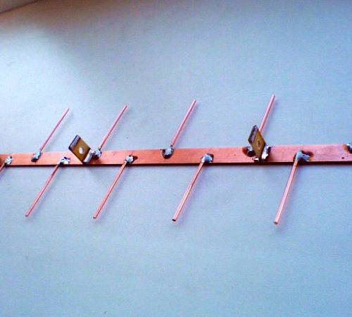
In the AMB range, due to a decrease in the effective length of the receiving antenna, with an increase in frequency, a lower voltage develops at the antenna input than under the same conditions in the meter range. Therefore, it becomes necessary to install antennas with a high gain. In antennas of the "Wave channel" type, this is achieved by increasing the number of directors, creating in-phase arrays from multi-element antennas (Fig. 10.30). Since the dimensions of the antenna elements of adjacent channels differ slightly, they are usually given for a group of channels (Table 10.20).
Table 10.20

13-element "Wave channel" antenna consists of three reflectors, an active loop vibrator and 9 directors. The distance between the ends of the loop vibrator A is 10 ... 20 mm. The diameter of the antenna vibrators is 4 ... 8 mm. The antenna gain is 11.5 dB, the opening angle of the main lobe of the radiation pattern in the horizontal and vertical planes is 40 °.
19-element Wave channel antenna for the UHF range (Fig. 10.31) consists of three reflectors, an active loop vibrator and 15 directors. The vibrators are made of 4 mm diameter wire and tubes. They are attached in any way to a supporting boom with a diameter of 20 mm. The boom length for any group of channels is 2145 mm (table 10.21). The antenna gain is 14 ... 15 dB, the opening angle of the main lobe of the radiation pattern in the horizontal and vertical planes is 30 ... 32.
Broadband antenna of the "Wave channel" type for reception in channels 21 ... 41(fig.10.32).
Depending on the distance to the television transmitter and the zone of reliable reception of its signals, the number of antenna elements (directors) can be reduced to 8.11 or 15.
In the case when preference is given to receiving in one television channel (for example, receiving an NTV program from the village of Kolodishchi), the dimensions of the antenna elements and the distance between them can be recalculated for this channel.

Table 10.21

The UHF broadband antenna has the highest gain (13 dB) in the 28th channel, the average frequency of which is 500 MHz. The conversion factor (Kp) in this case is determined by the formula


where fcp is the average frequency of the UHF channel, MHz. For the 37th channel, the average frequency of which is 562 MHz, Kp is equal to:
Kp = 530/562 = 0.943.
Multiplying the dimensions of the elements and the distance between them by 0.943, we get the dimensions of the antenna for the 37th channel (Fig.10.33). You can also recalculate a broadband antenna for any channel (or group of channels) UHF. The center frequency of the channel (group of channels) is given in table. 10.2, the length of the half-wave loop is in table. 10.1. When using a metal supporting boom (traverse), the dimensions of the elements obtained when recalculating are increased by half its diameter.
The channel antenna gain increases to 14 ... 15 dB. An antenna of eight elements is used at a distance of 20 ... 30 km from the village. Kolodischi, from 11 - up to 30 ... 40, from 15 elements - up to 50 ... 60 km. An antenna of 24 elements is used behind the zone of reliable reception at a distance of 70 ... 90 km. To ensure good quality of the received image, an antenna amplifier is installed directly on the mast.
The antenna is less susceptible to the influence of closely spaced objects and has good repeatability. Deviations of up to 2 mm from the calculated dimensions are permissible with practically no deterioration in the antenna parameters.
Antenna of the "Wave channel" type with a complex passive reflector(Figure 10.34; Table 10.22 ... 10.24) consists of a lattice reflector (Figure 10.35, a), two canvases of which are installed at an angle of 90 ° at the end of the supporting boom, an active loop vibrator (Figure 10.35, b) and 18 directors.

In this case, the first two directors (A1 and D2) are two-story and spaced vertically by the thickness of the bearing boom (Table 10.23).
Table 10.22


The main advantage of such an antenna is reliable shielding of the rear hemisphere due to an increase in the SPL when installing a complex reflector. The latter concentrates the energy of the useful signal in the direction of the active vibrator, which helps to increase the antenna gain.
Table 10.23

Table 10.24


In fig. 10.36 is a side view of the antenna described above. 6-element antenna is designed for short-range reception at a distance of up to 10 ... 15 km from a television transmitter: 10-element - 15 ... 25; 15-element - 25 ... 40; 20-element - at a distance of 40 ... 60 km and more.
In the UHF range are widely used frame antenna Triple square, whose frames are made of a single piece of copper, brass wire with a diameter of 2 ... 3 mm. With the dimensions of the decimeter range (Table 10.25), the antenna has sufficient rigidity. The wire must be bent in a certain way (Figure 10.37). At points A, B and C, the wires must be stripped and soldered. In this design, instead of a loop (see Fig. 10.12) made from a piece of coaxial cable, a quarter-wave short-circuit bridge (see Fig. 10.11) is used, the same length as the loop (see Table 10.5). The distance between the bridge wires remains the same (30 mm). The design of such an antenna is quite rigid, and the lower boom is not needed here. -

The feeder is tied to the right wire of the bridge from the outside. When the feeder approaches the vibrator frame, the cable sheath is soldered to point X ", the central conductor - to point X. The left bridge wire is fixed on a dielectric stand or, in the case of an external antenna, on the mast. It is important that the feeder and the mast stand are not located in the space between the bridge wires ...
If you have copper, brass or aluminum strips, you can make diamond antenna(fig.10.38). The strips (1) are overlapped with screws and nuts. There must be a reliable electrical contact at the point of contact of the plates. The thickness of the strips is arbitrary.
The diamond-shaped antenna can operate in the frequency band of channels 21 ... 60, its gain is 6 ... 8 dB. To increase it, the antenna can be equipped with a reflector (Fig. 10.39).
The simplest reflector is a flat screen made of tubes or pieces of thick wire. The diameter of the reflector elements is not critical (3 ... 10 mm). The reflector sheet (2) is attached with the support-posts (3) to a metal or wooden mast (4). Points 0 have zero potential with respect to the ground, so the struts (2) can be metal.
Table 10.25


Feeder (5) - a cable of the RK type with a characteristic impedance of 75 Ohm is laid to power points A and B. The cable sheath is soldered to point B, and the central conductor to point A. At For long-range reception, the diamond-shaped antenna can be equipped with a broadband amplifier (6).
2-element Swiss antenna(see Fig. 10.21) can also be used in the UHF range (Table 10.26).
Table 10.26

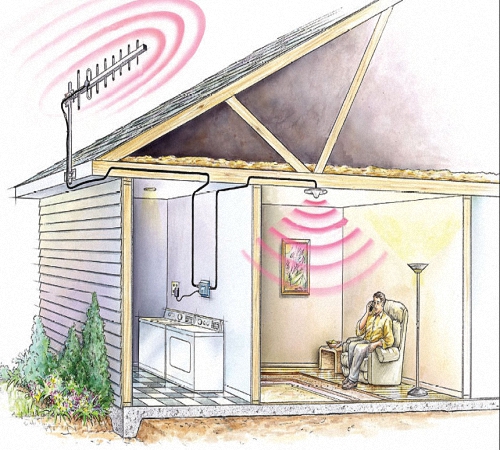
In country houses and summer cottages, problems often arise with the reception of television signals due to the lack of amplification. This may be due to the features of the relief, the presence of trees and other factors. Therefore, many owners of private properties are wondering how to make an antenna for digital TV with their own hands. If you have certain knowledge and skills in working with a soldering iron, this problem can be solved quite easily. Such antennas are distinguished by simple design, good reception quality, reliability and low cost.
Simple TV antenna
A repeater located up to 30 km from the signal receiving point allows you to use a simple design of a television antenna. It consists of two tubes connected by a shielded cable. The output part of the cable is fed to the corresponding input on the TV.
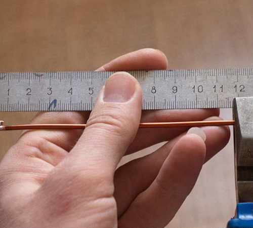
Before designing such an antenna, you need to find out the broadcasting frequency of the nearest TV tower. Typically, the broadcast bandwidth is 50 to 230 MHz. The entire strip is divided into 12 channels, each of which corresponds to a certain length of tubes. They are selected using a special table. As the frequency of the channels increases, the length of the tubes and cables will decrease.
Antenna materials:
- Metal tube, 8-24 mm in diameter, made of steel, brass, duralumin and other metals. The most commonly used diameter is 16 mm. Both tubes must have exactly the same parameters, up to the wall thickness.
- The required amount of TV cable with a resistance of 75 ohms.
- Getinaks or textolite for the holder, at least 4 mm thick.
- Clamps or metal strips used as pipe fasteners.
- Antenna stand can be made from a metal pipe or a corner. For low heights, wooden blocks can be used.
- You will definitely need a soldering iron, solder and copper. Silicone, epoxy resin or electrical tape are used to protect the soldering points.
How to assemble the antenna:
- First, the tube is cut to the required length, corresponding to the broadcasting frequency, and cut exactly in half.
- Each tube should be flattened on one side and attached to the holder with these ends. The distance between the near pipes is 6-7 cm, between the far ones - in accordance with the table. Fastening is carried out using clamps.
- The resulting structure is fixed on a post or on a mast. Then, the proximal ends are connected together with a cable loop. The middle cores of the cable are soldered to the flattened ends, their braid is connected with the same conductor.
- The center conductors of the loop and the cable supplied to the TV are connected. Their shield is also connected using a copper wire.
After completing all the steps, the loop is attached to the bar in the center, and the cable going down is screwed here. It is better to tune the antenna together: one person is needed to rotate the antenna, and the other to view and evaluate the image quality. After establishing the highest quality signal reception, the antenna is fixed in this position. You can navigate in the direction of the receivers installed in neighboring houses.
Loop antenna from pipe
The loop antenna manufacturing process is considered more complex than the previous version. This is due to the use of a pipe bender. However, the basic materials remain the same. You will need a metal tube, cable, and rack material. This design allows you to receive a signal at a distance of up to 40 kilometers.

The pipe can be bent to any radius. Of great importance is the observance of the required length and distance between the ends, which is from 65 to 70 mm. Each half of the bent pipe must be the same length. The center of the mast is the axis of symmetry for both ends. The choice of the length of the pipe and cable is also carried out using a special table. The average tube diameter is 12-18 millimeters.
Antenna assembly procedure:
- The tube is sawn off to the required length, after which it is bent at both ends so that they are symmetrical about the center.
- One end of the tube is flattened and then plugged by welding or soldering. After that, its inner cavity is filled with sand, and the second side of the pipe is also sealed. In the absence of welding, you can use plugs with glue or silicone.
- The resulting antenna design is fixed to the rack. The center wires of the cable loop are attached to the ends of the pipe. A cable is screwed to one end that goes to the TV. The cable sheath is connected with stripped copper wire. All joints are carefully soldered.
After assembling and installing the antenna, its tuning is performed in the same way as for the previous design.
Beer cans for outdoor antenna
Antennas made from beer cans have a high signal reception quality. For the manufacture of this structure, you will need 2 beer cans of 0.5 liters each, a wooden or plastic piece, about 0.5 m long, a television cable, a soldering iron, solder and flux for.

Digital antenna assembly:
- In the center of the bottom of each can, you need to drill a hole with a diameter of 5-6 mm. A cable is pulled through it and taken out through a hole in the cover.
- The finished can is secured to the left on a wooden or plastic holder. The direction of the cable should be towards the center of the holder.
- Then, from this can, a part of the cable, 5-6 cm long, is pulled out. It is necessary to remove the insulation from it about 3 cm and disassemble the braid.
- The released braid is trimmed to a length of 1.5 cm, spread over the plane of the can and soldered.
- The center conductor protruding 3 cm is soldered to the bottom of the other can.
- The distance between the cans should be minimal and fixed with electrical tape or tape.
This completes the antenna assembly. Further, the entire structure is installed and configured. The required plug is installed on the free end of the cable, plugged into the corresponding socket on the TV. All contact points must be carefully soldered and protected from external influences.
Antenna frame design
To make a loop antenna, you need a TV cable and a wooden cross as a base. Fastenings will be done with electrical tape and nails. First of all, it is necessary to calculate the perimeter of the copper wire frames. For the manufacture of frames, a wire is taken from a television cable. Calculations are carried out in accordance with the broadcasting frequency and channel number.

Before starting the assembly, you need to remove the insulation and braid from the television cable and release the center wire to the desired length. Antenna frames will be made from it. This procedure requires extra care to avoid damage to the copper strand.
The wooden frame is made according to the size of the frames. First, the main points are marked with nails - the corners. The distance between them from one nail to the other will correspond to the side of the square. Laying the conductor starts from the middle on the right, then it goes along all the designated points. The frames in the place of the minimum distance should not touch each other in order to avoid short circuits. The gap between the conductors is on average 2-3 cm.
After laying the entire perimeter, 3-4 cm of the braid is removed from the cable, which is twisted into a bundle and soldered to the left edge of the frame. The rest of the cable is laid along the core and fixed with electrical tape. Further, it is brought to the decoder and this is where the editing process ends. Thus, the question of how to make an antenna for digital TV with your own hands is solved in several ways. A feature of these TV devices is the ability to tune to only one frequency. Therefore, the design of such an antenna is simple and efficient.


