BIOS plays an essential role in the operation of a computer system. User settings saved in the BIOS largely determine the efficiency of the computer system as a whole or its individual subsystems.
Correct BIOS setup can significantly improve system performance or stability. Inappropriate handling of BIOS parameters leads to computer malfunctions, and in some cases - to complete system failure.
To customize the parameters of the basic I / O system, there is a special program built into the BIOS of all versions and manufacturers. Traditionally, you can enter it only when you turn on and restart your computer.
NOTE.
V Lately appeared special programs that allow you to access the BIOS while you are running. However, in most cases it is still better to configure the basic I / O system with staff program built into the BIOS.
To enter the setup program BIOS settings Typically, you need to press a key or key combination after turning on or restarting your computer. Most commonly used Delete key... However, this is not the only way... Quite often, the following keys and their combinations are also used to enter the BIOS setup utility:
Others can be used. keyboard shortcuts... In most cases, a prompt appears on the screen, like Press to Enter Setup, which disappears after a while. Sometimes the tooltip is not displayed so that inexperienced users are not too tempted to experiment.
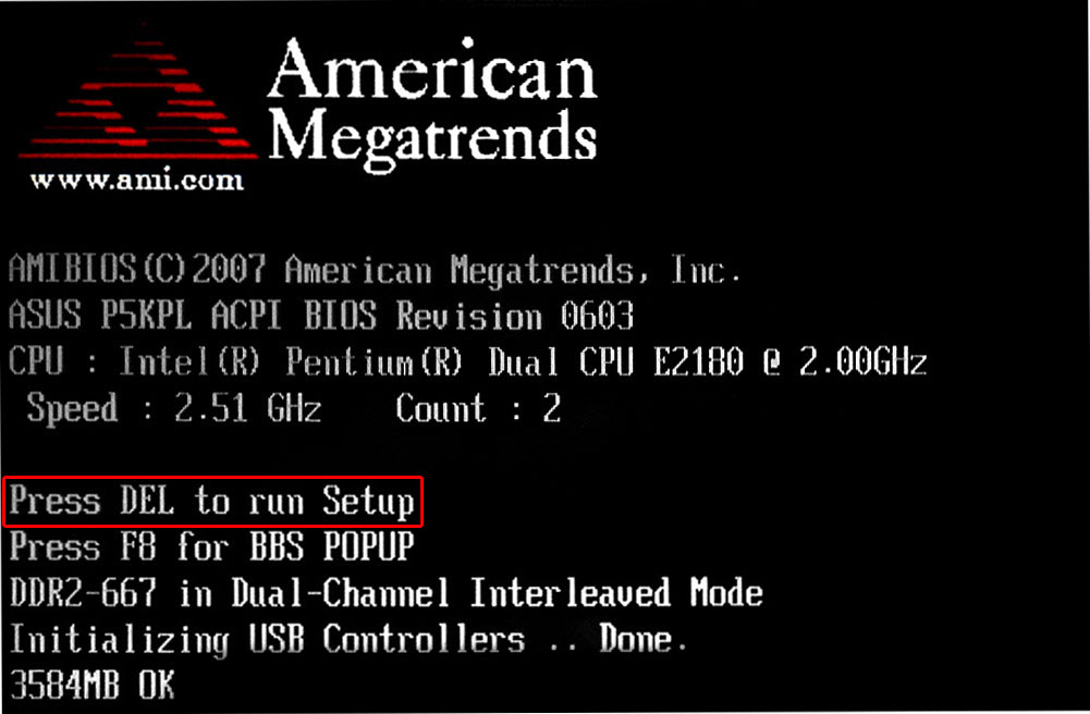
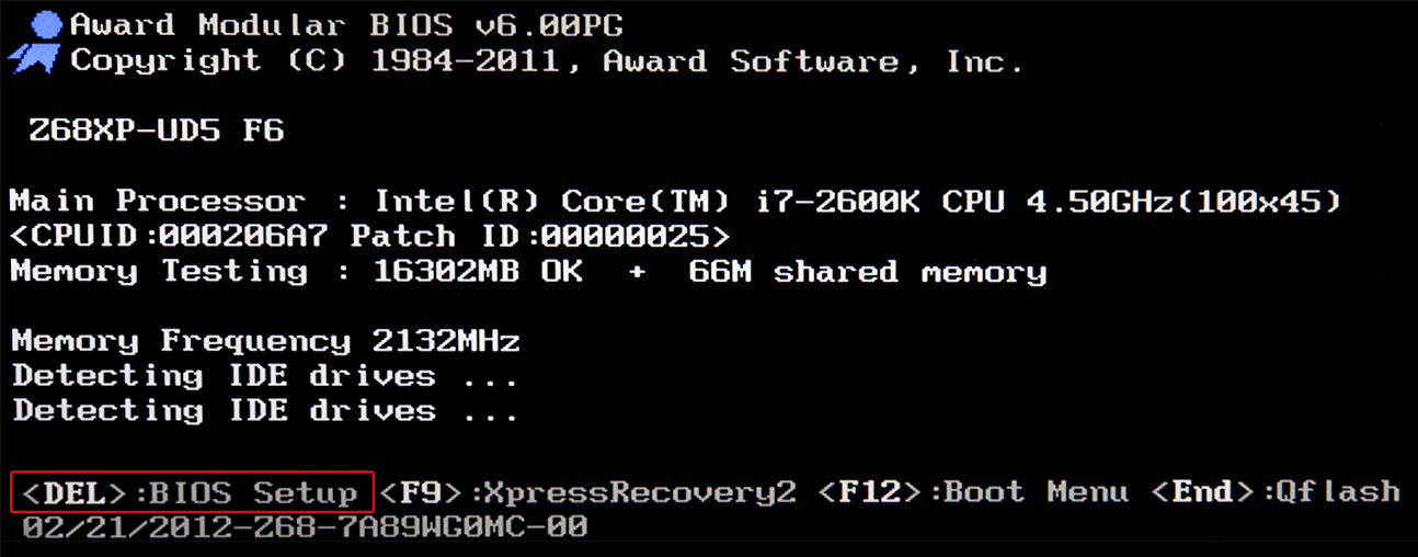
The basic I / O system for almost all computers is produced by just three major manufacturers. The most famous of these is Award Software (now legally a division of Phoenix) (Figure 3.3).
Rice. 3.3. Appearance Award BIOS.
Award BIOS is installed on most computers in the world. The most famous Award BIOS versions are: 2.50, 2.51, 2.51U, 2.51G, 4.51PG, 6.0 and 6.0PG.
The BIOS version number, as well as the manufacturer, and often even the release date, can be seen when the computer is turned on (usually on the bottom line of the screen). Almost all modern computers there are Award BIOS 6.0 or 6.0PG versions.
Previously, the BIOS from American Megatrends Inc (AMI) was very popular (Figure 3.4). At a time when the market was dominated by computer systems based on 80386 class processors, AMIBIOS was installed on almost all computers. Recently AMIBIOS has been used less and less often, although such manufacturers motherboards Like Gigabyte and MSI, they still frequently refer to the BIOS of this company. Sometimes AMI BIOS is installed on ASUS motherboards.
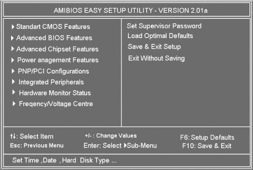
Rice. 3.4. Appearance of AMIBIOS.
AMI BIOS is characterized by much less flexibility in settings than Award BIOS, although its interface changed quite noticeably from version to version. Currently, only two AMI BIOS versions are distributed - 1.24 and 1.45.
Occasionally you can find BIOS from other manufacturers. Of these, Phoenix stands out. Some time ago, she was actively involved in the development own versions BIOS, however they all had big disadvantage- small amount custom settings... Respectively, computer system using Phoenix BIOS, it was very difficult to optimize for your own tasks (and often even impossible). Because of this, motherboard manufacturers began to phase out the Phoenix BIOS.
As a result this company and she herself decided to abandon the development of her own BIOS versions. Phoenix BIOS currently only uses Intel, whose motherboards are not popular.
However, as mentioned above, today Phoenix acquired Award Software, the main BIOS developer for modern computers. Wherein trademark The award was retained as being more popular among computer and motherboard manufacturers.
In addition to the small number of settings, Phoenix BIOS has another unpleasant feature: often, to change its parameters, you need to rearrange the jumpers or change the position of the microswitch.
The BIOS setup program can have a different user interface, but traditionally it consists of several sections, each of which contains parameters that are similar in meaning or related to similar settings.
The standard BIOS setup interface is quite archaic. When the user enters it, the main screen appears, in the upper part of which is the name of the program, information about its manufacturer, etc.
Its middle part lists the program sections that have the following names in the Award BIOS 4.51PG version:
Standard CMOS Setup- serves to set the date and time, as well as determine the configuration disk drives- various drives and hard drives;
BIOS Features Setup - in this section you can set the order of polling media in search operating system, as well as adjusting the parameters of the cache memory, processor, keyboard and hard drives;
Chipset Features Setup - collected here various settings operating parameters of the motherboard chipset, as well as the speed of access to random access memory;
Power Management Setup - this section designed to determine power saving modes, the behavior of the power button Power supply as well as tracking temperature regime and the rotation of the cooling fans;
PNP / PCI Configuration - allows you to configure the distribution of resources between devices;
Load BIOS Defaults - command to load the default parameters to ensure the most stable computer operation;
Load Performance Defaults is also a command to load the default parameters to ensure the most productive work of the computer;
Integrated Peripherals - this section contains settings for the IDE controller operating modes, computer ports and other integrated devices;
Supervisor Password and User Password - here you can set passwords to enter the BIOS setup program and boot the computer in general;
IDE HDD Auto Detection - serves for automatic detection parameters of rigid disks installed in the system;
Save & Exit Setup - means exit from the BIOS setup program with saving all the changes made;
Exit Without Saving - exits the BIOS setup program without saving the changes made.
One of the listed sections in the program window is always highlighted in color. Moving through the sections is carried out using the cursor keys. To enter the highlighted section, use the Enter key (sometimes Space). Using the F2 keys and the Shift + F2 combination, you can change color range program interface. To exit the program without saving the changes made, press Esc, and while saving the changes, press F10.
At the bottom of the main screen, there are key tips and short description highlighted section. For example, when the Standard CMOS Setup section is selected, the Time, Date, Hard disk type inscription appears at the bottom of the window, briefly explaining the essence of the section parameters.
To enter the selected section, press Enter. A list of parameters will appear on the screen, opposite each of which its current value is indicated. One of the parameters is always highlighted.
Use the cursor keys to move between the parameters. You can change the values of the selected parameter using the Page Up and Page Down keys, or "+" and "-". If you need to restore the parameters that were current before entering this section, press F5. F6 is for loading the default settings for this section for the most stability, and F7 for the most performance. In addition, using the F2 key (and the Shift + F2 combination) here you can change the color scheme, and by pressing F1, you can display a brief help.
To exit the selected section, use the Esc key. In this case, all changes made are saved in a temporary buffer. Thus, it is possible to discard the changes made by exiting the BIOS setup program without saving the changes made.
Though standard interface BIOS setup programs, more familiar to most users, sometimes there are BIOS setup programs with a different interface. For example, AWARD BIOS version 6.0 (but not 6.0PG) inherited the interface from the Phoenix BIOS, and as a result, the Phoenix-style interface has become quite common again in recent years. Sometimes it is also used in BIOS from AMI company.
The main screen of the Phoenix BIOS settings program is characterized primarily by the fact that in its upper part there is a line of sections (highlighted by inversion), where their names are listed in a short form (for example: Main, Advanced, Power, Boot and Exit). In this case, moving between sections is carried out using the "left arrow" and "right arrow" keys.
The content of the highlighted section is always displayed in the main part of the screen. Use the? Keys to move between parameters. and?. The values can be changed using the "+" and "-" keys (sometimes also traditional Page Up and Page Down). By clicking Enter key, you can get it full list possible values selected parameter (and then select the one you want).
The F1 key brings up help. Quick reference for the selected parameter is always on the right side of the screen. The default values of the selected partition can be loaded by pressing F5.
The F10 key exits the setup program and saves the changes, and the Esc key does not save the changes.
To the left of some of the options are triangular arrows indicating that these options are actually directories that contain a list additional parameters with their meanings.
In some cases, the BIOS setup utility may use a windowed graphical interface... It is convenient to make settings here with the mouse, although all changes can be made without using it. Such an interface is typical, in particular, for some AMI BIOS versions (as a rule, not the newest ones).
When using the windowed interface, each section of the parameters on the screen is located in separate window... To get into additional window with a list of possible values, you need to double-click on the required parameter. Desired value can also be selected with the mouse.
If the mouse is not connected to the computer or is not detected by the BIOS setup program, you can navigate between windows using the Tab key, and select options in active window by means of cursor keys. To change the value of a parameter, use the Enter key.
Despite a certain ease of navigation, such interfaces for the BIOS settings programs have not become popular and are extremely rare today.
In some emergency situations you must reset all BIOS parameter settings to their default state. In most cases, this can be done from within the BIOS setup utility itself, but sometimes this method is not suitable.
For example, after incorrect installation clock frequency processor or any bus, the computer may stop loading or the image will disappear on the monitor. In addition, you cannot enter the BIOS setup program if you have forgotten the password to enter it (although in this case one of the engineering passwords that are suitable for all BIOSes of a particular version can help).
If the computer cannot boot due to incorrect BIOS settings, you can reset the parameters in the initial state... This can be done in two different ways depending on the motherboard.
The first is as follows. Look in the documentation for the motherboard where the pins and the jumper for resetting the BIOS settings are located on it. If there is such a jumper, turn off the power to the computer, open the computer case, find this jumper on the motherboard and set it to the reset position. Then (without closing the computer case) turn it on for 15-20 seconds (while the screen remains dark) and turn it off again. Then return the jumper to its normal position, close the case, and turn on the computer again. It should start downloading normally.
ATTENTION!
Before installing the jumpers on the motherboard, it is advisable to physically disconnect the power from the computer. Otherwise, the consequences can be the most unpleasant. The fact is that power continues to flow to the computer's motherboard, even if it is turned off by software.
The second way to reset BIOS parameters (software) is used if the jumpers are not provided on the motherboard. In this case, you need to turn on the computer, while holding down any key (which one is written in the documentation for the motherboard) on the computer keyboard. Usually C or K are used for this.
If the two considered methods were unsuccessful, you can try the "non-standard" methods of resetting the BIOS parameters. The easiest way is to remove the battery of the CMOS chip on long time- it may take more than a day for the capacitors built into the power microcircuit to discharge.
Another method is to short-circuit the CMOS pins to the computer case. This should be done with the power off using a wire, the ends of which are stripped of insulation. For closing, select an unpainted place in the case. Discover necessary conclusions CMOS is possible experimentally - only the CMOS microcircuit is powered from the battery, so any other such short circuit with the power off cannot damage.
If the computer somehow works, but you need to reset the BIOS settings, you can use programmatically- write to the port with hexadecimal address 70 any number in the range from 10 to 2F (hexadecimal values), and to the port with hexadecimal address 71 - any value that is not equal to the previous one.
And if you recklessly switch its parameters, the system will not start until it is successfully reset. Errors that programmers make when compiling it lead to annoying glitches and incompatibilities, but as they are eliminated, it is updated and quite amenable to flashing - just make sure that power supply will not disappear during it, otherwise there will be trouble. Our hero is a biggie, they call him BIOS. And his entire title sounds like this: Basic Input-Output System, which translates as “ base system input-output ".
What is it and why
BIOS is small program EEPROM (Electrically Erasable Programmable Read-Only Memory) or flash memory, which is about the same. The motherboard BIOS is the first software that a computer uses immediately after turning it on. Its task is to identify devices (processor, memory, video, disks, etc.), check their health, initiate, that is, start, with certain parameters and then transfer control to the operating system loader.
In fact, BIOS is found not only on the motherboard, but also on other computer nodes - up to network adapters... However, we decided that the "mother" bios should become the hero of our article, because it is precisely the manipulations with it that are most often performed by users.
So, the PC owner can control the BIOS behavior within a fairly wide range. First of all, you can reflash it, that is, erase the contents of the microcircuit, and then write a new one. This feature is used to update the BIOS code. In new versions of the firmware, errors made by developers are eliminated and adequate support for new devices is introduced (for example, new models of processors or RAM).
The second way of interfering with the BIOS is less dramatic, but gives the user great amount opportunities. This is a change in the parameters that are set by the hardware when the system starts up. They are stored in volatile CMOS memory (there is a battery on the motherboard to save these settings). In order to change these settings, you need to press a certain button when starting the system - which one, the computer will write (for example: "Press Del to enter Setup"), after which the inscription "Entering Setup ..." appears, and then the interface BIOS management... And it was him detailed description and the rest of the article is devoted.
BIOS of all common motherboards are based on code written by one of two companies: American Management, Inc. (AMI) or Award. They are somewhat different from each other, but in general they are similar. We will be looking at AMIBIOS. Once you understand it, you can easily navigate in AwardBIOS.
Since it is not very practical to consider a "spherical BIOS in a vacuum" (it will be more difficult to explain what's what), for example, let's take the ASUS Rampage II Extreme motherboard for Core processors i7 made by LGA 1366. Its choice is primarily due to its very rich functionality. Having delved into its settings, the reader will be ready to meet even the most sophisticated motherboards - there is hardly anything unfamiliar in their BIOS. However, some of the nuances specific to this platform will be noted and explained in more detail. Go.
How to set up BIOS correctly?
After launch computer BIOS starts the Power-On Self Test (POST). During it, the motherboard shows the user the manufacturer's logo or data on the passage of the equipment check (depending on current settings). At the bottom of the screen at this time it is written how to enter the BIOS setup interface and, just in case, how to call the utility BIOS flashing(it is in the bios of the overwhelming majority of relatively modern motherboards, starting with the Socket A platform, and allows you to update the microcode without loading the OS).
In this case, the BIOS is entered by pressing Del. In this case, the computer will write that it enters the settings interface, and then displays it. In the case of AMIBIOS, the main part of the screen will be occupied by open tab Main, in which the most basic parameters of the system can be configured. To move to another tab, use the left and right arrows. List of tabs with an indication of the active in this moment displayed at the top as a menu bar.
The contents of the Main tab, like the rest, are vertically divided into two fields of unequal size. The left one contains configurable settings and sometimes additional diagnostic information. The item on which the cursor is positioned is highlighted in white by default. Contextual tips in English are displayed in the right margin - they help you quickly get used to the interface. The up and down arrows are responsible for moving between the tab items. You can select an item by pressing Enter.
Basic parameters start with the system time and date. Everything is obvious with them. Their values can be entered from the keyboard in numbers, and can be increased and decreased using the "+" and "-" buttons. The Legacy Diskette A parameter controls the floppy drive. It can be set to Disabled, 720K, 3.5 in, and 1.44M, 3.5 in, with the latter option set by default. You do not need to switch it. The Language parameter can change the interface language from understandable English to incomprehensible Chinese, German and French. People who know these languages better than English may find this setting useful. We will continue to review the English-language interface.
The following items are responsible for drives and drives connected to SATA ports. Most often, these are correctly detected automatically, and you do not need to change anything in the SATA X items, where X is the port number.
The next section is called Storage Configuration and, as you might guess, is most directly related to configuration disk subsystem... Going into it, you can find the items SATA Configuration ( allowable values: Enhanced, Compatible and Disabled) and Configure SATA as (can be set to IDE, ACHI or RAID). Obviously, similarly named menu paragraphs are responsible for different things, but what exactly does each one do?
SATA Configuration allows, firstly, to disable the SATA controller soldered on the motherboard (great, right?) By selecting Disabled, secondly, to set the Enhanced mode adopted when using modern operating systems, and thirdly, to transfer the disk subsystem to compatible with the old OS (Windows 95, 98, Me) (Compatible) mode. Moreover, you can work in this mode on new systems, but the number of disk devices connected to the SATA controller will be limited to four. Older operating systems could not imagine that there could be more of them (it was believed that there are a maximum of two IDE channels, each for two devices).
Configure SATA as allows you to show the operating system disks as IDE devices (then even when working under Windows 2000 or XP there will be no problems and will not be required additional drivers), for which you need to select the IDE value. If you are using an OS that allows this, you can install the advanced ACHI (Advanced Host Controller Interface) mode, in which you can use NCQ (natural command queue) technology, hot plugging and other progressive chips. The third mode serves, as the name suggests, to create disk arrays.
RAID stands for "Redundant Array of Independent Disks", that is, a redundant (meaning by reliability) array of independent disks (I will clarify that RAID 0 is an exception - it is not more, but less reliable than a single screw). To configure the array, after activating this mode, enter the RAID controller configuration utility, for which on this motherboard, press Ctrl + I during POST.
The two remaining items, Storage Configuration, Hard disk Write Protect and SATA Detect Time out, are responsible, respectively, for write protection of disks (of course, it is better not to activate it) and the time the computer searches for disk subsystem devices upon startup. The shorter this time, the faster loading, and it makes sense to increase it if disks or drives for some reason do not have time to be detected during POST.
If SATA devices are switched to ACHI mode, another item will appear in the menu - ACHI Settings. It will set the timeout for starting from optical media (ACHI CD / DVD Boot Time out) from 0 to 35 s, step 5 s. It will also display submenus of the SATA X type, in which it will be possible to turn off self-diagnostics (set SMART Monitoring to Disabled) or itself disk device, more precisely, the corresponding SATA port (SATA port X for this needs to be transferred from Auto to Not Installed).
Having dealt with the modes of the disk subsystem, we can return to a higher level in the menu and see what's what in the SATA X items (X is the port number). Yes, you should almost never change anything there, but getting to know these submenus still does not hurt.
So, Type is the kind of device. You can force CD-ROM or ARMD (ATAPI Removable Media Device, means ZIP drives, magneto-optical drives, and similar exotics).
LBA / Large Mode is responsible for supporting screws larger than 504 MB, and therefore it is highly recommended to select Auto over Disabled from the two possible values.
Block (Multi-Sector Transfer) allows you to disable the transfer of several sectors of 512 bytes at a time and thus greatly reduce the speed of the disk (one sector will be transferred in one pass). For more or less modern hard drives with a SATA interface, choosing Disabled does not make sense. Leave it as it is.
PIO Mode allows you to impose an outdated data exchange mode on the disk, since automatically any modern hard disk drive operates in PIO 4 mode, the fastest of the five (from 0 to 4). PIO stands for "Programmed Input / Output Mode", that is, "programmed I / O mode". There is no need to change the default Auto.
DMA Mode is a little closer to our time than PIO. DMA stands for Direct Memory Access. This mode complements the PIO and has a much higher speed (the fastest PIO 4 - 16.6 MB / s, the fastest DMA - 133 MB / s). Naturally, all modern screws, especially with SATA interface, work in the fastest UDMA 6. Just in case, I will clarify that SWDMA (Single-Word DMA) is the most braking mode, MWDMA (Multi-Word DMA) is not a gallop for you either, but it will still be faster, and UDMA is deservedly called "Ultra DMA" because it is faster than others. Moreover, the higher the number after the name of the mode, the higher the speed. Switch Auto value on something impractical.
SMART Monitoring is a useful and quite modern thing. Technology allows tracking state of tough disk, measuring its various parameters and noting how they change over time. From this data, S.M.A.R.T. (Self Monitoring Analysing and Reporting Technology, technology of self-observation, analysis and reporting) make a conclusion about how long will live HDD And isn't it time to take care of data backup and screw replacement. If S.M.A.R.T. for some reason it does not turn on automatically (modern hards are on friendly terms with it without fail), you can try to set "Enabled" manually. In other cases, you should trust the Auto mode. It is unlikely that you will need to forcibly turn off self-diagnostics, but there is such a possibility.
Finally, 32 Bit Transfer sets 32-bit for Enabled and 16-bit for Disabled for data transfer via the PCI bus or the internal chipset bus. 16-bit mode is naturally not recommended.
In the main BIOS menu there is only one item left - this is System Information, that is, general information about the system. It shows the BIOS microcode version number and release date, the model of the installed processor and its clock frequency, the amount of RAM in the system. Since the motherboard under consideration has two BIOS chips, it is also written here which of them is used, how it is selected (by hardware, that is, by a jumper, or programmatically, from the corresponding BIOS section). The names for the first and second BIOS are also displayed.
There is nothing else in the main BIOS settings section (smiley). But even the above is enough to appreciate the abundance of opportunities. Yes, it is better not to change most of the parameters (such as fine-tuning the disk subsystem) here, since this will not cause anything other than a drop in the operating speed, but it is possible and even useful to switch devices to AHCI mode, for example. Configuring RAID arrays may also be required.
Gourmet menu
Having informed that when entering AMIBIOS an open Main tab will appear, I was cheating a little. V general case it will be so, but on some motherboards, and in particular on ASUS Rampage II Extreme, you will first find yourself in a special “ command post», Where the overclocker's tools are collected; and the Main tab was moved to second place. And this is reasonable, because Extreme Tweaker (this is how the overclocking toolkit is called in this case) is in demand much more often. Note that the functions of overclocking, as well as monitoring frequencies, voltages and temperatures, each manufacturer of motherboards implements a little differently. Therefore, the description of those for one motherboard will help you get used to overclocking and acquire a certain horizons, but will not serve as verbatim guides for fine tuning any PC.
The two lines at the very top of the page tell you at what frequency the CPU and RAM will work after applying your BIOS settings. They are labeled "Target CPU Frequency" and "Target DRAM Frequency" respectively.
The following four parameters are responsible for automatic overclocking. CPU Level up allows you to switch the CPU to a frequency of 3.6 (i7-crazy-3.60G) or 4.0 GHz (i7-crazy-4.00G), while the rest of the parameters related to the processor frequency, such as voltages at different nodes, a caring mother will arrange it herself. As you might guess, Memory Level up has about the same effect, only on memory - you can set the RAM frequency to 1600 or 1800 MHz, the system will select the rest of the parameters. You cannot use both Level Up at the same time. The next item is responsible for the selection of the overclocking mode.
It is called AI Overclock Tuner and allows you to select the following: Auto (keeps the nominal frequencies and voltages), X.M.P. (i.e. eXtreme Memory Profile, a non-standard memory profile, allows you to select Profile # 1 or # 2, the first with aggressive timings, the second with increased frequency), CPU Level up (processor priority), Memory Level up (memory priority), ROG Memory Profile (allows you to choose one of three memory profiles: Speedy, Flying and Lightning, that is, "fast", "flying" or "lightning fast"), and finally, the most interesting Manual mode - that is, "manual".
V manual mode you can adjust the performance “from the processor” (OC from CPU Level up), “from memory” (OC from CPU Level up) and “from the bulldozer”, in the sense of a completely manual mode, guided only by your own considerations. Let's consider in order what can be adjusted by the "knobs".
CPU Ratio Setting, as the name suggests, sets the stone's multiplier value. A multiplier is an integer or half-integer number that the base frequency is multiplied by to produce the CPU clock speed. Most processors have a limited maximum multiplier, however, stones of the Extreme series from Intel and Black Edition from AMD have the multiplier unlocked - you can increase it above the nominal value. Sometimes the multiplier needs to be decreased, for example, in order to increase the frequency of the processor or memory bus when constant frequency the CPU itself (in particular, when its ceiling is reached).
CPU Configuration displays information about the stone (shows manufacturer name, frequency, base frequency, cache sizes of 1st, 2nd and 3rd levels, maximum multiplier, current multiplier, CPUID). In addition, it, again, allows you to change the multiplier (CPU Ratio Setting) and enable or disable various technologies supported by the stone. For what these technologies are used, we will see in the second part of the article. In the meantime, let's figure out the funds for overclockers.
Tuning forks
BCLK Frequency is the most important point for the overclocker, as it allows you to change the Internal Base Clock. The processor frequency is calculated as the product base frequency and the CPU multiplier. Thus, if the maximum multiplier of the stone is fixed (and this is most often the case), raising the base frequency is the only way to overclock the stone. You just need to remember that it is called basic for a reason - it is a kind of tuning fork for the entire system; apart from the CPU, it is oriented towards it, along with the CPU, the QPI bus (more on it a little later), and the north bridge (non-core CPU components). Therefore, when increasing the base frequency, remember this and, if necessary, lower the multipliers of the overclocked components. Because of this, overclocking is a creative activity (smile). You can set the Base Clock by typing in the desired number from the keyboard or by adjusting the current value with the "+" and "-" buttons. By default, the reference frequency (sometimes the Base Clock is translated like this) is 133 MHz.
By the way, the same principle applies when overclocking AMD stones. But on the LGA 775 platform, the processor frequency depends on its external FSB.
PCIE Frequency allows you to change the frequency PCI bus Express. Considering that more sane methods have been invented for overclocking video cards, at least the same RivaTuner program, it makes no sense to move this parameter. But you can try. Remember only that an increase in this frequency above the nominal value quickly leads to instability and it should not be raised above 115 MHz.
DRAM Frequency is the frequency of Dynamic Random Access Memory. No other has existed in the PC for a very long time. Unfortunately, you cannot set the desired frequency by simply typing in a value from the keyboard - there are fixed factors, that is, the RAM frequency must be selected from several options. Naturally, during overclocking, this menu item will almost certainly be needed.
UCLK Frequency is the Uncore Clock Frequency, which is the memory controller built into the CPU. It also depends on the base frequency and also on the memory frequencies. With a loss of stability on high frequencies processor, you can try to manually slow down the memory controller - it might help. But it should be remembered that its frequency should be at least twice the hertz of RAM.
QPI Frequency is the frequency of the external processor bus. Since it also depends on the BCLK, it is likely that it will have to be downgraded if stability is lost. By the way, the QPI (Quick Path Interconnect) bus was made by analogy with HyperTransport, an external processor bus on AMD platforms... Therefore, having met the HyperTransport bus multiplier in the BIOS of a motherboard for AMD stones, you will know what it is for and can reduce it if necessary.
Sense of tact
DRAM Timing Control allows you to control RAM latency. The point is that RAM synchronizes data operations with the clock signal. The delays between these operations are expressed as an integer number of ticks and are called timings. By default, the values of these parameters are taken from the SPD microcircuits on the memory modules and are tied to the RAM frequencies. Their decrease leads to an increase in performance or to a loss of stability, that is, it is an overclocking method. There are five main memory timings: CL, tRCD, trp, tras and CR.
DRAM CAS # Latency is also called CL. This is the delay between giving a command to read or write a column and executing it. Strongly affects the speed and stability of the system, is selected individually.
DRAM RAS # to CAS # Delay, aka tRCD. Delay between RAS # for row selection and CAS # for column selection. You can also try to lower it, but the stability after that must be carefully checked.
DRAM RAS # PRE Time, or trp, is the delay caused by recharging the memory bank. The fact is that the RAM consists of capacitors, which tend to discharge, and quite quickly. And therefore, a charging mechanism is provided. This parameter determines how many measures it takes. If you set the value too low, the charges of the capacitors will be lost along with the data that they indicate.
DRAM RAS # ACT Time, or, equivalently, tras, is the minimum time for a row to be active. It should be said here that memory is arranged like a table with rows, columns and cells at their intersections. At the same time, as a result of the physical and logical structure of modern RAM, if it is necessary to do something with a memory cell, the entire row is read. And while the PC is working with one line of memory, it cannot do anything with the others. It must first deactivate the line, that is, leave it alone. And he can do this not earlier than the tras delay expires. Therefore, in some tasks, where software has to deal with data scattered in a mess all over the memory, this timing significantly affects the speed of work.
DRAM RAS # to RAS # Delay (abbreviated as trrd) is one of the minor timings. Sets the minimum time between commands to read lines from different banks of memory (memory is subdivided into banks in accordance with its architecture). The parameter can not be changed, it will still be a little confusing.
DRAM REF Cycle Time (trfc) is the minimum time between two recharge cycles. Refers to non-core timings.
DRAM Write Recovery Time (abbreviated as Twr) is the time that must elapse after writing before starting to recharge the memory. Timing is not the main one, and it is not easy to find it.
DRAM READ to PRE Time (Trtp for short) - almost the same as previous item, only after the operation, not writing, but reading. It is also never the main parameter.
DRAM FOUR ACT WIN Time (tfaw) is the minimum active time of four lines from different memory banks. Minor timing.
DRAM WRITE to READ Delay (twtr) - as the name implies, the delay between the write and read processes (more precisely, the end of the write and the issuance of the read command).
DRAM Timing Mode is, paradoxically, the most important timing. More often it is called CR (tcr), or Command Rate, is 1, 2 or 3 clock cycles. This is the delay between the issuance of any command by the memory controller and the start of its execution. If the memory is of sufficient quality to withstand the 1T mode (in this case it is designated for some reason 1N), it is better to install it. CR of three measures is the least desirable option. Why was such an important thing not considered at the very beginning?
For an elementary reason - in the BIOS menu, which I now describe point by point, this important setting pushed far enough away from the top of the page in favor of numerous not very useful secondary timings. For what reasons this was done is unknown, but it should be borne in mind that desired options BIOSes are not always in the most prominent place.
DRAM Round Trip Latency on CHX, where X = A, B, C, is the delay between the sending of a command from the memory controller and the arrival of a response to it on the corresponding memory channel (A, B, or C). It consists of many timings, and is not regulated by it. absolute value, and acceleration (Advance n Clock, that is, "accelerate by n clock cycles") or slowdown (Delay n Clock, "delay for n clock cycles"). This setting should affect the speed and stability of the computer, but how exactly it functions is difficult to say: after all, it is not known due to which terms, that is, simpler, non-composite timings, this value changes. You can experiment. Controlling this parameter is not implemented on all motherboards, but this is no big deal - the same effect can be achieved by playing with the main timings. In this case, there are three points - according to the number of memory channels.
Remember that memory is made up of multiple banks? So, banks are logical and physical (physical are subdivided into logical). The physical bank is also called "rank" (in Russian it can be translated as "rank", but no one translates, they say: "rank"). What am I doing? But why ...
DRAM WRITE to READ Delay (DD) defines the delay between writing and reading on different modules(DD is Different Devices, different devices) memory.
DRAM WRITE to READ Delay (DR) controls the amount of time between writing and reading at different ranks, that is, physical banks of memory. DR stands for Different Ranks, therefore different ranks.
DRAM WRITE to READ Delay (SR) sets the same value in meaning, only for operations on one rank (and SR is, of course, Same Rank, "the same rank").
DRAM READ to WRITE Delay (DD), (DR) and (SR) are responsible for adjusting the delay between read and write for the same three cases, respectively.
DRAM READ to READ (DD), (DR) and (SR) and DRAM WRITE to WRITE (DD), (DR) and (SR) are six more settings, they allow you to set the number of cycles from read to read and from write to records in the same cases.
All these menu items, a total of 12 items, can be useful for fine-tuning the memory subsystem, however, experimentally choosing them is not an easy task and is solved slowly and thoughtfully. They are not found on all motherboards and do not belong to the basic settings, but they will come in handy for an enthusiast - provided that he has free time.
Voltage
EPU II Phase Control is a proprietary ASUS technology... It allows you to dynamically disconnect the processor power phases when the load on it drops. Other developers of motherboards have similar technologies. The sense from them is dubious. Full Phase mode provides maximum stability, especially in overclocking, since phases are not disabled in it; it is better to opt for it. Although for an energy-efficient media center, it is better to activate such a feature (translate to Auto) - its processor does not often need increased power supply.
Load-Line Calibration allows you to compensate for the voltage drop on the processor when the load on it increases (Vdroop). The voltage sags due to the fact that the conductors through which power is supplied to the stone have their own resistance, sufficient so that when the current increases, the voltage drop across them is significant (according to Ohm's law, it will be U = IR). When overclocking, it is better to enable this option forcibly, but before that it is not out of place to find out if it functions correctly on your motherboard model, because it can be implemented with an error and then it does not help, but interferes.
CPU Differential Amplitude sets the differential clock amplitude. This means that by default the difference between the minimum and maximum voltage clock signal is equal to 610 mV (when the value this parameter Auto). With an increase in the clock frequency, not only the speed of the stone increases, but also the amount of interference, due to which the percent can "listen" to the clock signal, which will lead to errors. If you increase the amplitude from the default value to at least 700 mV, the interference can be blocked. The option can and should be used in case of loss of stability during overclocking.
Extreme OV allows the user to raise the voltage on the devices very high. At the same time, the survival of the processor and other hardware is not guaranteed by the manufacturer, so you should use this opportunity only when experimenting with extreme cooling, for example, with liquid nitrogen. However, this approach has not been canceled, and the chip can be very useful for setting records.
CPU Voltage regulates nothing more than the supply voltage of the stone. Feeding the CPU is sometimes necessary to stabilize overclocking. Before raising the voltage on the cores above the nominal value, it is imperative to find out what maximum value recognized as safe for the model of stone you are accelerating, and do not exceed it. By the way, this function can be used to reduce the voltage on the processor and thereby heat it up in the same media center.
On this motherboard model, the BIOS marks the voltages that are potentially dangerous to the CPU in red, and those that are significantly high - in yellow. Such a useful indication comes across often, but not everywhere.
The CPU PLL Voltage is the supply voltage for the Phase Locked Loop system. Increasing it should contribute to more successful overclocking, however, if you decide to do it, take care of cooling the processor power subsystem - it will get very hot.
QPI / DRAM Core Voltage regulates the voltage on the memory controller and the QPI bus. Their feeding may be needed if these nodes become a "bottleneck" during acceleration. A similar setting, by the way, is also found on AMD platforms (only there it is called HT Voltage) and is also useful.
IOH Voltage is responsible for powering the north bridge. Like other “gastronomic surpluses”, it promotes confident work at overpriced clocking. In this case, as in the previous one, you must act carefully so as not to burn the processor. Before starting experiments, you should find out the limits beyond which it is dangerous to output these voltages.
IOH PCIE Voltage changes the voltage on those PCIE bus lines that are provided northbridge... There is no need to use this.
ICH Voltage allows you to regulate the voltage on the south bridge of the motherboard. Why this may be needed is difficult to say. It is best not to touch this setting.
ICH PCIE Voltage makes it possible to feed those PCIE lines that owe their existence south bridge... Since we considered overclocking PCIE inexpedient (see above), this parameter can be safely left alone.
DRAM Bus Voltage controls the voltage in memory. The thing is necessary, because many modern operational-memory modules have even the most nominal voltage higher than the generally accepted norm. And for overclocking the RAM, it never interferes with raising this value.
DRAM REF Voltage is used to set the reference voltage amplitudes on each of the three channels of the memory controller. The thing here, again, is the appearance of interference when operating the RAM at high frequencies. If you increase the reference voltage amplitude, that is, the difference in voltage between zero and one, it will be easier for the memory to perceive data and commands. At the same time, using DRAM DATA REF, you can adjust the data bus, and DRAM CTRL REF will help you adjust the command bus. On most motherboards, these points are not separated, but the memory channels are almost always regulated independently of each other.
Racing ammunition
Debug Mode allows you to choose how to display error messages. The motherboard, taken as an example, can output to special screen not only POST codes (two hexadecimal digits that must be deciphered using the instructions or the manufacturer's website), but also meaningful messages in English. This feature is useful, but specific and rarely seen. Even the presence of a simple indicator of POST codes on the motherboard is already a big plus. In this case, by choosing String, in case of a glitch, we get an English-language explanation. Choosing Code - two digits, from 0 to F each.
Keyboard TweakIt Control enables or disables keyboard control of TweakIt technology. This technology is the very same screen for displaying POST messages and other purposes, as well as control buttons on the motherboard. With it, you can quickly view and change, without going into the BIOS, system parameters - frequencies and voltages. This economy is intended for the convenience of overclocking, bench sessions and tests. Uncommon and expensive. Other firms have analogues.
CPU Spread Spectrum allows you to reduce the number of electromagnetic interference, but sometimes makes it difficult to overclock the BCLK reference frequency. The effect is achieved by smoothing out the peaks of the clock signal, which may cause problems with clock recognition by devices. It is worth forcibly activating this somewhat dubious option only when processing sound in order to reduce the influence of high-frequency
How do I set the system date and time? How do I boot my computer from a CD or flash drive? These and other common questions can be answered by getting acquainted with the basic BIOS settings and how to edit them.
Introduction
If you still do not know what BIOS (BIOS) is and what this firmware is for, then we advise you to read our previous material about how it works. bootstrapping computer, and what role the "basic input / output system" plays in this process. In the same article, we will get acquainted with the BIOS setup program, which is most often called BIOS (CMOS) Setup Utility.
By the way, in most cases, users use abbreviated names of this program, calling it BIOS Setup or just BIOS. For example, you can often hear expressions such as "enter BIOS" or "open BIOS", which is somewhat incorrect, since in both cases we are talking about entering the BIOS Setup program, which is only part of the BIOS.
Most BIOS cases Setup is used by ordinary users only to set the system time and date or select boot devices a. But in fact, this program can have a ton of possibilities. With it, you can control the operation of the processor, RAM, chipset and others important components PC, monitor the temperature regime of devices and carry out many other useful actions.
Entering BIOS (CMOS) Setup Utility
In order to launch the BIOS setup program, you must press a certain key or a combination of these keys during the initial PC testing procedure. In the overwhelming majority of cases, desktop computers to enter BIOS Setup, use the Del key, less often F1 or F2. In laptops, on the contrary, most often they are used for these purposes. function keys(F1, F2, F11, F12).
Find out exactly which keys are used for BIOS startup Setup can be found in the instructions for your computer or motherboard. Also, in some cases, during the POST procedure, a hint is displayed on the monitor screen about which key must be pressed to enter the settings.
True, in modern computers and laptops, screen prompts are less and less common, but in any case, find desired key will always help search query in the Internet.
In addition to the need to know the required key, to enter BIOS Setup, it is equally important to select right moment pressing it. In order not to be late, it is better to repeatedly press the enter key immediately after the PC starts booting. In most cases, this method is guaranteed to launch the BIOS settings.
BIOS interface (CMOS) Setup Utility
The Bios Setup program has a text-based interface without any design tweaks and is controlled exclusively using the keyboard. This is explained by the fact that the graphical shell of this application has practically not changed since the 80s, so everything looks very simple and ascetic.
In general, the BIOS Setup interface is of two types: with the main menu located in two columns or horizontally. You can understand what type in front of you immediately after entering the program and opening its main window.
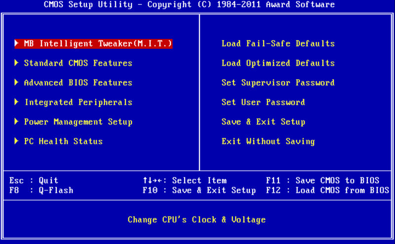
In the first case, you will see on a blue background a list of sections arranged in two columns. This option is typical for BIOS versions developed by Phoenix Technologies (AwardBIOS, Award Modular BIOS, Award WorkstationBIOS). Their traditionally in their motherboards ah are used by manufacturers such as MSI, Gigabyte, Foxconn, ECS and others.
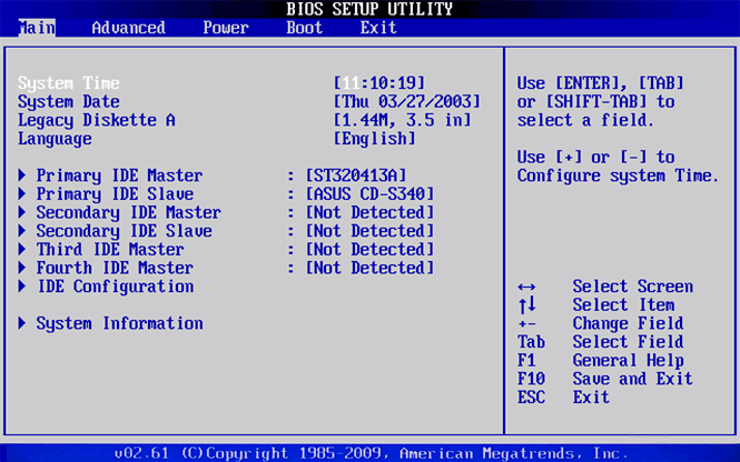
In the second case, you will see a window with gray background, in which the menu with the main sections will be located at the top of the screen, in the form of a blue horizontal bar. Such an interface is usually inherent in the BIOS of American Megatrends (AMIBIOS, Aptio AMIBIOS) used in motherboards ASUS boards, Intel, ASRock and some others.
Despite such differences in the interface of these two options, all BIOS Setup sections have a similar presentation. To verify this, let's look at the structure of the program windows in both cases.
At the top of the screen, you will always find the name of the current section (in the case of horizontal menu name is highlighted) or subsection.
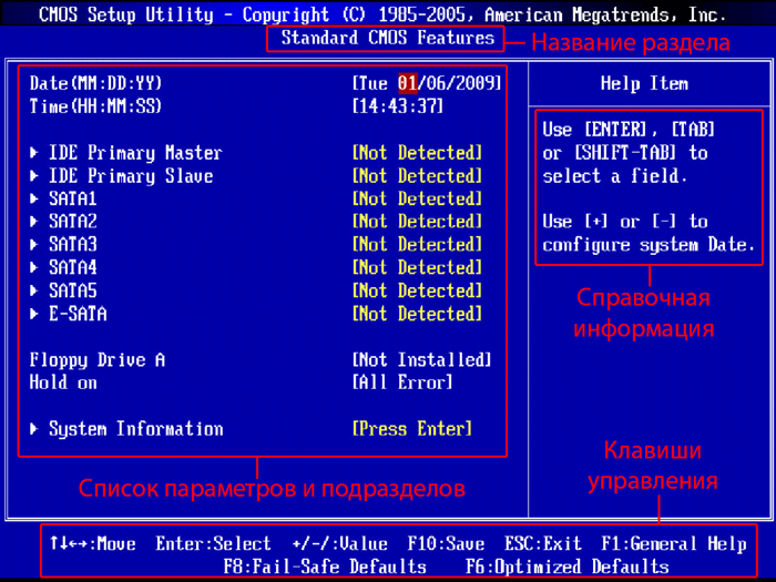
The main part of the screen is occupied by the area in which the list of subsections (indicated by triangular arrows) and parameters of the selected section is located. To the right of the parameter names are their values. It should be borne in mind that if a parameter is highlighted in a pale color (blue or light gray), then it either has a read-only status and is for informational purposes only, or to edit it, you need to change another parameter associated with it.
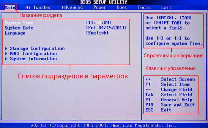
The right side of the screen is usually occupied by a column, which displays brief help information on the selected parameter or subsection, as well as tips on possible actions and the use of control keys (American Megatrends). In BIOS setup with a blue background, the function key prompt is usually located at the bottom of the screen.
As you can see, despite the different colors and small differences in the arrangement of work items on the screen, in essence both interfaces are very similar, and present information to users in almost the same way. That is why the methods of working with BIOS parameters are practically the same in both cases.
Use the arrow keys to navigate through the menus and select the required parameters, subsections or sections, and the “Enter” key to open them. The "ESC" key is responsible for returning to the previous screen and exiting the current settings. Also, using this key, you can exit BIOS Setup without making changes to the settings by pressing it in the main menu. In addition, the functions of the "F1" keys, which call up help, and "F10", which initializes the exit from BIOS Setup, from anywhere in the program, with saving the changes, are unchanged. The "PageUP" / "PageDown" or "+" / "-" keys are traditionally used to iterate through the available values of the parameters being changed.
In addition to the above keys, other function keys (“F2” - “F9”, “F11”, “F12”) can be used to work with BIOS settings, but their function may differ depending on the motherboard model and manufacturer. However, in order to understand what each of them is responsible for, it is not difficult. It is enough to refer to the tips that appear on the screen or look through the manual for the motherboard.
Main sectionsBIOSSetupcolumnar main menu (blue background)
Each motherboard model in many cases has its own unique set customizable parameters, but at the same time the names and thematic focus of the main BIOS partitions Setup usually remain unchanged.
Standard CMOS Futures
This section contains the basic (standard) computer settings, which include: setting the system date and time ( Date, Time), parameters of disk drives ( IDE Channel), as well as various information about the system (information about installed processor, the amount of RAM and others).
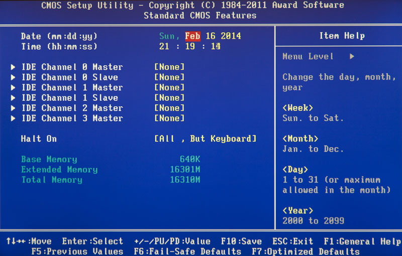
By the way, setting the date and time for most users is one of the most important reasons for visiting BIOS Setup.
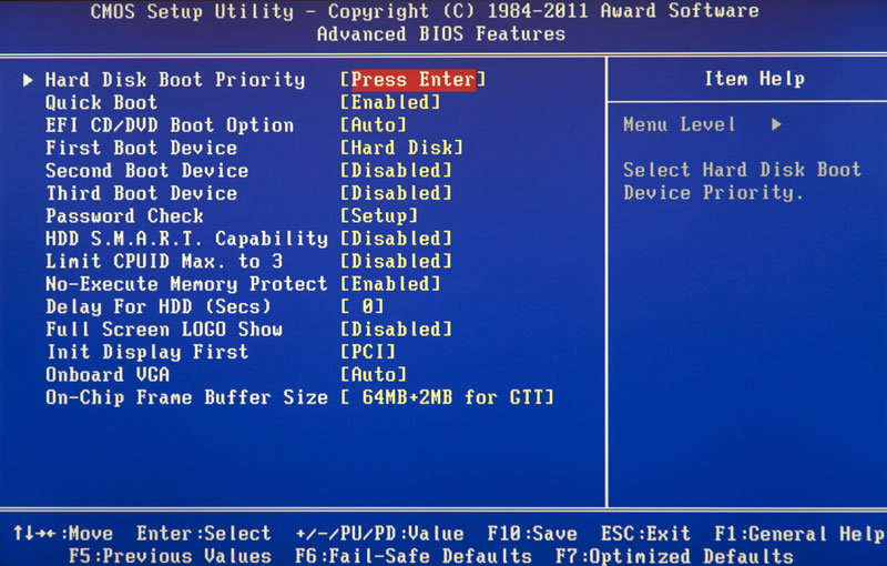
Advanced BIOS Features
This section contains advanced BIOS settings. The most common ones include:
- Cache management central processing unit
- Parameters related to the nuances of computer boot. For example, here you can enable / disable NumLock mode, mode accelerated loading (Quick Boot ), as well as showing the logo of the board manufacturer during the self-test procedure ( Full Screen LOGO Show).
- Selecting the sequence for polling boot devices ( First / Second / Third Boot Device). Another most requested feature in BIOS Setup, along with setting the date and time.
- Enabling / disabling self-monitoring technology hard disk S.M.A.R.T.
It should be noted that depending on the model of the board and BIOS modifications the set of settings in this section may vary.
Advanced Chipset Features
This section describes the settings of the chipset installed in the motherboard, as a result of which the set of parameters here directly depends on its type and modification. In most cases, here are the options that are responsible for the operation of the RAM (frequency and timings adjustment), the data exchange bus between the processor and RAM, the AGP / PCI-E graphics bus and the video adapter.
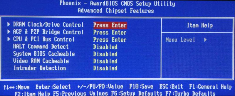
It should be noted that in some situations it is by changing the parameters of this section that you can increase the speed of your computer or, as they say, overclock. True, in recent years, the options responsible for increasing the speed of a PC are most often carried out by manufacturers in a separate specialized section of the BIOS.
Integrated Peripherals
This section contains the parameters responsible for the operation of integrated into the motherboard, peripheral devices as well as: controllers hard drives, USB ports, sound and network adapters, and others.
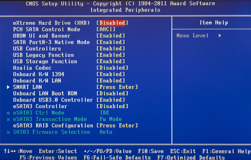
For example, here you can enable / disable the built-in sound card, support USB input devices or select a RAID mode to create array of hard disks.
Here are the options that are responsible for the power supply and power saving modes of the computer. Almost all modern computers allow power management directly from the operating system, but this requires BIOS support for the specialized ACPI standards, the mode and functions of which are regulated in this section.
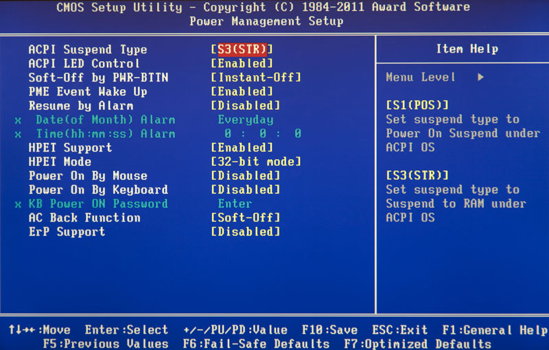
Also here you can specify what actions should take place when you press the power button, set up the conditions for turning on the PC and its transition to reduced power consumption or exit from hibernation.
PnP / PCI Configurations
This section contains control parameters for Plug and Play technology, which is responsible for the distribution of resources between PC devices and their quick configuration, as well as settings for the PCI bus. As a rule, these functions are successfully performed by the system and do not require manual intervention. Therefore, in modern computers, this section may be absent altogether.
PC Health Status ( H / W Monitor)
Modern motherboards are always equipped with sensors that monitor the operating temperatures and voltages of the main devices, as well as the rotational speed of the cooling fans. All their indicators are just displayed in this section.
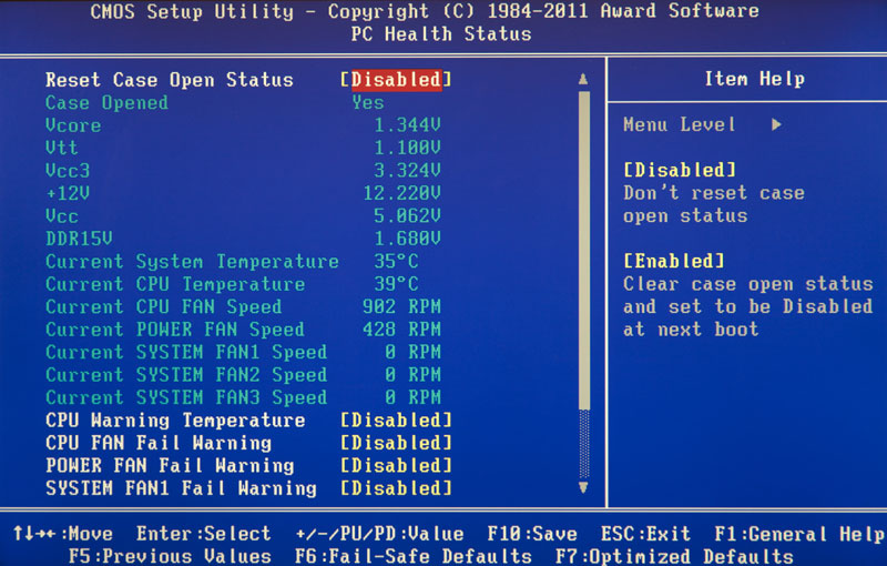
In addition to this in the PC Health Status you can control the operating modes of the fans and set up alert options in case of overheating, stopping the cooler, or opening the case cover.
Frequency / Voltage Control
This section contains the parameters responsible for setting operating frequencies and voltage values for the processor, RAM, video card and other devices. By default, all frequencies and voltages have the recommended values and are automatically adjusted, which guarantees reliable performance systems.
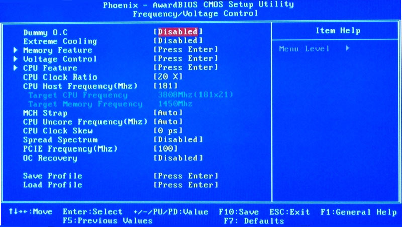
However, the value of some of the parameters in this section can be changed manually. This makes it possible to overclock the processor, memory and other components, forcing them to work at higher frequencies. You just need to remember that, on the one hand, overclocking allows you to increase the overall performance of the system, and on the other hand, it can cause malfunctions in the PC and cause the overclocked hardware to fail (for example, when setting overvoltage values). So you have to be very careful here.
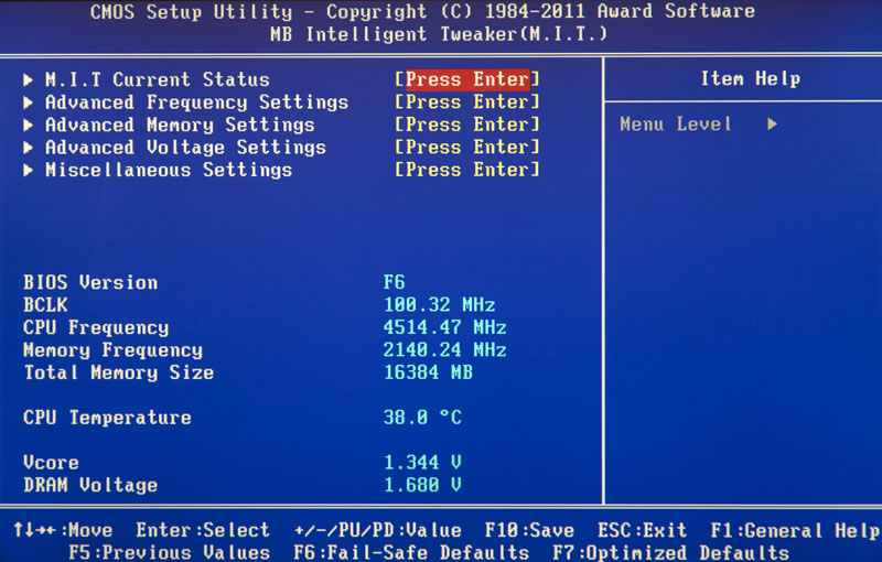
It is worth noting that many major motherboard manufacturers place options for setting frequencies and voltages in a special section with original name, For example MB Intelligent Tweaker (M.I.T.) or Cell Menu .
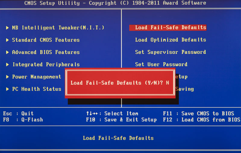
Load Fail- Safe Defaults
This is not a section, but a command that resets all BIOS settings to their defaults, which guarantees stable work the entire system. After selecting this item, a window will open in front of you, in which you will need to confirm the reset by pressing the "Y" key.
A command that sets the values of the BIOS settings in such a way as to ensure optimal performance of the computer while maintaining the stability of all its components. In this case, the parameters that are subjected to automatic change, depend on the motherboard model and may vary.
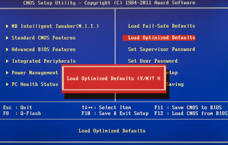
However, please note that such optimization of settings in some cases may lead to unstable work systems due to incompatibility installed equipment... Then you should return to the default settings using the command Load Fail-Safe Defaults and try to configure desired parameters manually.
Set Supervisor Password
A command that allows you to set, remove or change the administrative password that is used to full access to all BIOS settings, as well as when the PC boots.
Set User Password
A command that sets a user password that allows access to view the values of BIOS parameters. That is, most of the settings will be closed for editing. Same way given password can be used when booting the computer.
Main sectionsBIOSSetupwith a horizontal main menu (gray background)
As we already noted, the BIOS setup interface exists in two main variants, which differ not only external design and the location of the main menu, but also the arrangement of parameters by sections. So now let's take a look at the second kind of interface that is used by such mainboard market leaders as ASUS or AsRock.
Main
Based on the name, according to the developers, this section contains the main BIOS settings, which include time and date, parameters of installed disk drives and general system information(BIOS version, processor model, volume installed memory). In this way, Main is almost a complete analogue of the section already familiar to us .
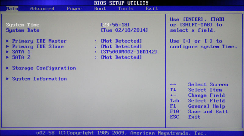
As you probably already guessed, the most requested option in this section is setting the system date and time.
Advanced
As a rule, this section has the largest number of options for configuring components and PCs and includes several significant subsections at once. Here are the parameters responsible for the operation of the central processor ( CPU Configuration), RAM, video adapter, chipset ( Chipset), PCI bus and Plug and Play ( PnP / PCI Configuration, PCI PnP), built-in peripherals ( Onboard Device Configuration), USB ports ( USB Configuration) and other equipment.
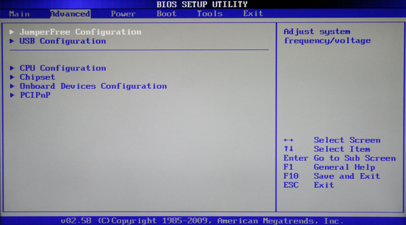
Also in this section you can find overclocking options that allow you to manually set the frequencies and voltages of the processor, memory, as well as the PCI-E bus. In some cases, users can additionally adjust the RAM delays (timings / latency). In many models of motherboards, the parameters responsible for overclocking are placed in a separate subsection (for example, JumperFreeConfiguration) or even an independent section of the main menu ( AiTweaker, Overclocking or ExtremeTweaker).
Due to the large enough set of components and the variety of parameters, section Advanced practically does not have a unified structure. Depending on the motherboard model and BIOS developer, the number of subsections / settings and their names can vary greatly. After all, if we compare it with the BIOS Setup version, which has blue background, it turns out that in the section Advanced collected the contents of five sections at once: Advanced BIOS Features, Advanced Chipset Features, Integrated Peripherals, Frequency / Voltage Control and PnP / PCI Configurations.
Power
This section is identical in content and essence to the sections and PC Health Status (H / W Monitor).
![]()
Here are the parameters responsible for the power supply and energy saving of the PC, monitoring the operating temperatures and voltages of its main components, as well as controlling the speed of rotation of the fans.
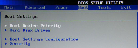
Boot
Already from the name it is clear that this section is responsible for configuring the boot parameters of the computer. It is here that the settings for determining the sequence of polling boot devices and enabling / disabling the "Num Lock" key, demanded by many users, are located (subsection Boot Settings Configuration).
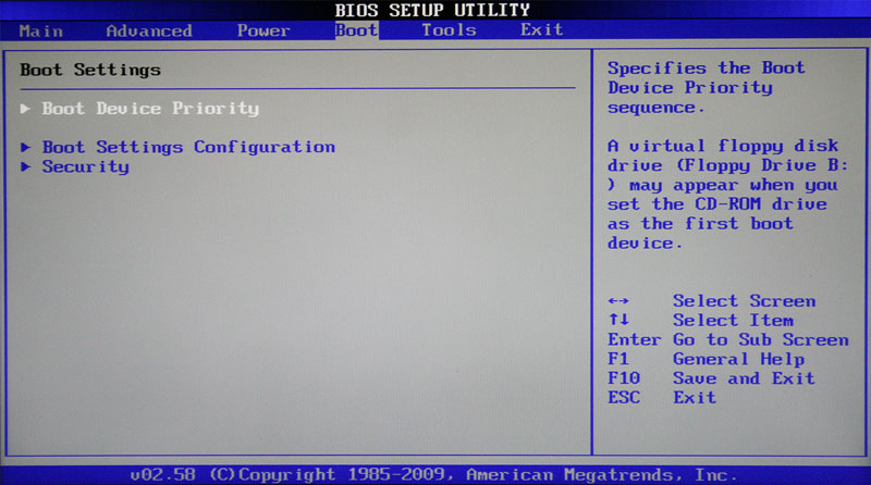
In many cases, the section Boot includes subsection Security containing commands to install, remove or change the administrative and user passwords... In some BIOS versions Setup password management parameters can be placed in a separate section of the same name.
Tools
Most motherboards from popular by ASUS, contains an additional section that contains auxiliary tools for BIOS updates (EZ Flash 2), disable / enable mini-OS on Linux kernel (Express gate), creating profiles individual settings BIOS ( O.C. Profile), as well as checking the connection network cable during PC boot ( AI NET 2).
Exit
This section is responsible for exiting the BIOS settings menu and combines commands such as:
- Exit & Save Changes- provides an exit from the program with saving all the changes you made.
- Exit & Discard changes - exits the program without saving all the changes made.
- Load Setup Defaults- Returns BIOS settings to their default values (reset to factory settings).
- Discard changes- canceling the changes made without exiting the program.
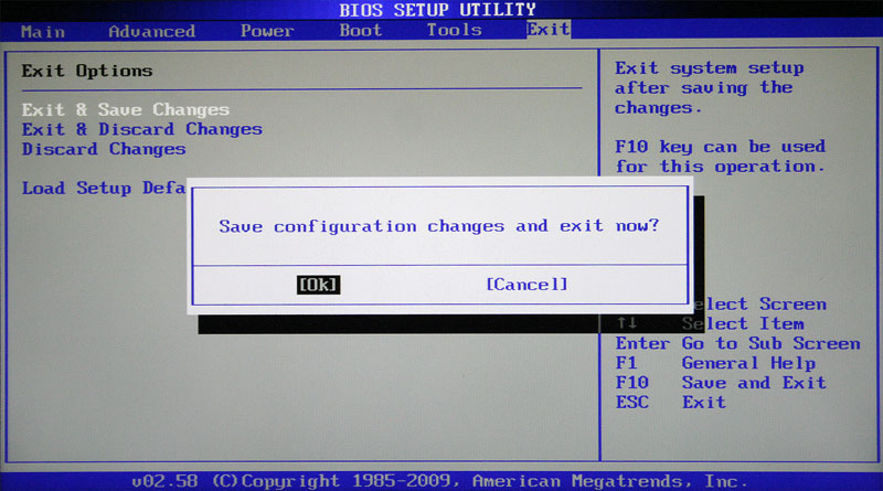
After selecting any of the above commands, a window will appear in which you must confirm its execution by pressing the "Y" key, and then "Enter"
Setting the time and date
When you turn on a new computer for the first time, it is better to immediately attend to the installation in BIOS correct system time and date values, thereby setting the baseline for both the operating system and software capable of functioning without an installed OS.
To enter the BIOS settings menu, immediately after the computer starts booting, press the desired key (usually "Del" or "F2"). After the main BIOS Setup menu appears in front of you, to achieve the set task, we perform a few simple manipulations.
BIOSSetup with blue background
Use the arrow keys to move the cursor to the section and press "Enter" ("Enter"). Often this section is the first and you don't need to move anything anywhere, but there are exceptions.
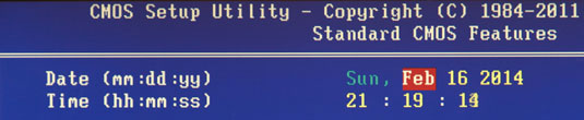
In the window that opens with options, from above we find the two parameters we need - Date and Time. Use the arrows to move between parameter values. To set the values, you can use both the "+" / "PgUp" or "-" / "PgDn" keys, as well as direct input of numbers from the keyboard. For fixing set values the "Enter" key is intended.
The general algorithm of actions here is quite simple: place the cursor on the required field (highlighted in red), enter or select its value and press "Enter". Next, go to the next field and repeat everything until all the parameters are set.
After all the values have been entered, to save the changes, press the "F10" key. In the red window that opens, enter the letter "Y" by pressing the key of the same name on the keyboard. After a reboot, the new time and date values will take effect.
BIOSSetup with gray background
Using the keys "←" and "→" select the section Main, although in most cases this will not have to be done, since it is almost always located first and opens by default immediately after entering BIOS Setup.
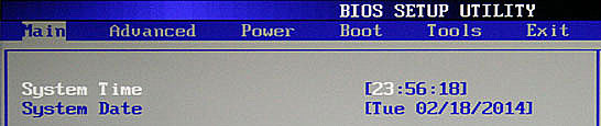
We find in this section System parameters Date ( System date) and System Time ( System time) and move the cursor there using the "↓" and "" keys. Further, to enter values, use either the number keys directly, or the "+" and "-" keys. To move between fields within one parameter, the "Tab" key is used here. After entering the required value, press "Enter".
Changing the boot device
When installing an operating system or conducting preventive work with an already installed OS, it is often necessary to ensure that the computer boots not from the hard disk, but from optical media, USB stick or some other storage device. Therefore, one of the most demanded tasks for which ordinary users have to "climb" into the BIOS settings is the need to change the boot device.
BIOSSetup with blue background
After opening the BIOS Setup program, move the arrows to the section and press "Enter".
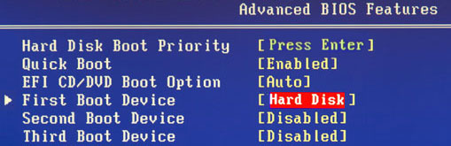
Use the "↓" key to go to the parameter (First boot device) and press Enter again.
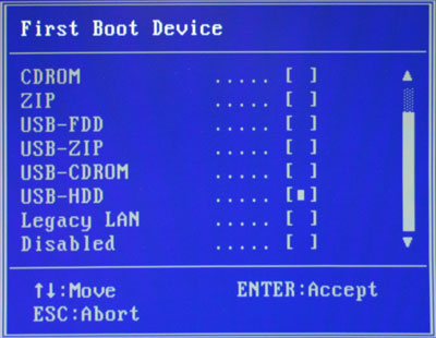
Next, you will see a window with a list of devices that you can select as bootable. If you plan to start your PC with optical disc, then use the arrows to select the CDROM value and then, as usual, "Enter". If you need to boot from a flash drive or external portable drive, then select the USB-HDD option. In the same way, you can select the second and third boot devices ( SecondBootDevice and ThirdBootDevice).
It should be borne in mind that if several hard drives are installed in the computer at once or solid state drives that contain the system and are bootable, then to indicate the sequence of their polling, it is intended special item HardDiskBootPriority.
In order for all the settings you made to take effect, do not forget to press the "F10" key, then "Y" and finally "Enter".
BIOSSetup with gray background
After opening the BIOS settings window, use the "→" key to select the item Boot and press "Enter". Then you can expect two options, depending on the BIOS version.
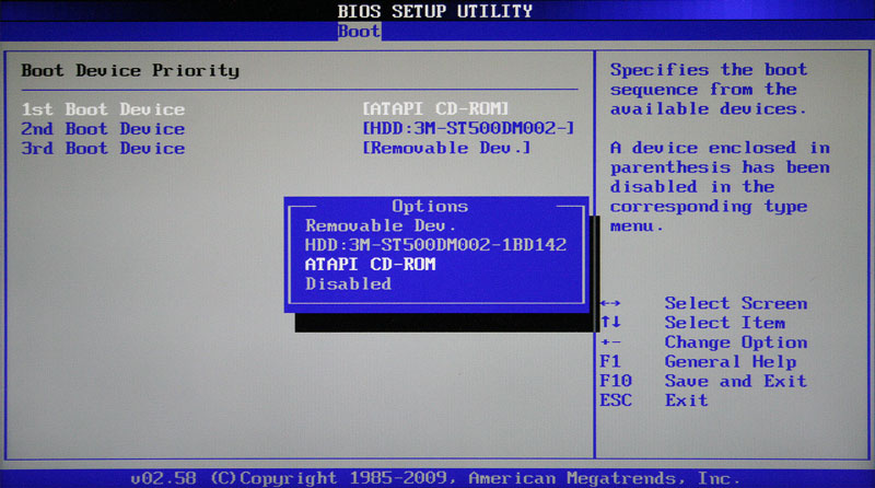
In the first case, you will immediately see a list of the destination of the boot devices. They are designated as 1st, 2nd and 3rd Boot Devices (respectively, the first, second and third boot devices). Moving through the list is done with the "↓" keys, selection of values (HDD, CDROM, USB, Removable) - with the "Enter" or "+/-" keys.
In the second case, the section Boot will contain several subsections, among which in this situation we are interested in the item BootDevicePriority... Move the cursor to it and press "Enter". Immediately after that, a window with a list of boot devices will open in front of you, the selection of which is carried out in exactly the same way as described above.
The owner of several drives should pay attention to the subsection HardDiskDrives... It is in it that the choice of the priority boot disk among the hard drives installed in the computer. If you have several optical drives, then in this case the choice of a priority device among them can be organized in the subsection CDROMDrives.
After completing the settings, it remains to press the "F10" key, and then "Enter" to save the changes.
Conclusion
Despite the fact that the BIOS is still the most common system used for initial setup hardware and PC boot, her time is inexorably coming to an end. Today, most motherboards are equipped with a new promising software boot interface - UEFI, which has a modern graphical shell and has much more functionality.
However, write off the "old lady" BIOS still early. After all, the mass adoption of UEFI began just a few years ago, while the BIOS is the main one. boot system for several decades. Therefore still for a long time, a huge number of computers with BIOS will be used by many users.