K. Kharchenko
Reception of television broadcasts at radio frequencies 470 ... 622 MHz (21-39 channels) of the decimeter wave range (DCW) requires an appropriate approach to the calculation and design of antenna devices.
Some radio amateurs are trying to solve this problem by simply recalculating, based on the principles of electrodynamic similarity of antennas, the parameters of existing designs television antennas meter range (1-12 channels). At the same time, they inevitably face the difficulties of the recalculation itself and often do not get the desired results.
What are the basic principles of approach to solving this problem?
In free space, the radio waves emitted by the antenna have a spherical divergence, as a result of which the electric field strength E decreases inversely with the distance r from the antenna.

V real conditions propagating radio waves undergo greater attenuation than exists in free space. To take into account this attenuation, the attenuation factor F(r) = E/Eb is introduced, which characterizes the ratio of the field strength for real conditions to the field strength free space for equal distances, the same antennas and the powers supplied to them, etc. Using the attenuation factor, the field strength generated by the transmitting antenna in real conditions at a distance r can be expressed as
The receiving antenna converts the energy of the electromagnetic wave into an electrical signal. Quantitatively, this ability of the antenna is characterized by its effective area Seff. It corresponds to the area of the wave front from which all the energy contained in it is absorbed. This area is related to the CPV by the relation:

The foregoing allows us to write a radio transmission equation that relates the parameters of communication equipment (transmitter and receiver) and antennas and determines the signal level on the path: at transmitter power P1, signal power P2 at the receiver input will be equal to

The factor in this expression, enclosed in brackets, determines the basic propagation loss of the radio waves (basic transmission loss). It is assumed that the antenna is matched with the feeder, and the feeder with the television receiver and, in addition, the antenna is matched in polarization with the signal field.
Let us consider expression (11) in more detail.

This specific example shows that with an increase in the frequency (reduction in the wavelength) of television transmissions, the power of the signal entering the TV input, all other things being equal, decreases rapidly, i.e., the reception conditions deteriorate. On the transmission side, they try to compensate for these troubles by increasing the product P1U1. But in real conditions, the factor F(r) and the efficiency of the receiving feeder decrease with increasing frequency, so the need to increase the gain of the receiving antenna Y2 becomes inevitable. This conclusion entails another one, which is that, as a rule, for confident reception of programs 21-39 TV channels it is necessary to use new, more directional antennas compared to antennas used in the 1-5 channel wavelength range.
In an effort to get stable TV reception, radio amateurs are forced to complicate antennas, for example, to build antenna arrays, i.e., they combine several antennas of the same type that have proven themselves in practice (each of which has its own pair of power points) with common system power supply and only one (common for all) pair of power points. At the same time, they often underestimate the importance of the coordination stage in the construction of antenna arrays associated with relatively complex measurements. Let us illustrate this with a specific example.

A similar effect is obtained when parallel connection three elements (Fig. 1, c). Continuing such reasoning, we can obtain the dependence illustrated in Fig. 2.

Here effective area antenna is directly proportional to the number n of radiators in the array, as well as the power absorbed by the antenna P sums. The power Р pr supplied to the receiver, with an increase in the number n, asymptotically approaches 4Рo. This example shows the futility of attempts to increase the gain of the antenna array without taking into account the coordination of its elements with the feeder. Difficulties associated with matching are overcome either by using special matching devices or by choosing special types of antennas. For example, in the decimeter and especially in the centimeter wavelength ranges, as a rule, so-called aperture antennas are used, that is, horn or parabolic. The peculiarity of such antennas lies in the fact that they have a simple, "small" feed, and a "large", relatively complex reflector. A large reflector determines the directional properties of the antenna, determines its directivity factor.
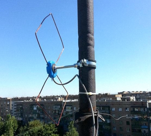
It is not possible to make aperture-type antennas for the DTSV range in amateur conditions, since they are bulky and complex. But some semblance of an aperture antenna can be constructed by assuming a feed in the form of a well-known zigzag antenna(h-antennas). The fabric of such an antenna consists of eight closed identical conductors, which form two diamond-shaped cells (Fig. 3).

For the formation of the antenna radiation pattern, in particular, it is necessary that the radiators are in phase and spaced relative to each other. The Z-antenna has one pair of feed points (a-b), to which the feeder is directly connected. Due to this design of the antenna, its conductors are excited as follows ( special case directions of currents on the antenna conductors in fig. 3 is shown by arrows), which forms a kind of in-phase array of four vibrators. At points P-P conductors the antenna webs are closed to each other and there is always a current antinode. The antenna has linear polarization. The orientation of the electric field vector E in fig. 3 is shown by arrows.
The radiation patterns of the s-antenna satisfy the frequency range with overlap fmax/fmin =2-2.5. Its directivity depends little on the change in the angle a (alpha), since with its increase, the decrease in the directivity of the antenna in the H plane is compensated by an increase in the directivity in the E plane, and vice versa. The directivity characteristic of the s-antenna is symmetrical with respect to the plane in which the conductors of its web are located.
Due to the fact that at the points P-P there is no break in the conductors of the antenna web, there are points of zero potential (voltage zeros and current maxima) here, regardless of the wavelength. This circumstance makes it possible to do without a special balancing device when powered by a coaxial cable.
The cable is laid through the point of zero potential P and the two conductors of the antenna web are led to its power points (Fig. 4). Here, the cable braid is connected to one of the antenna feed points, and the center conductor is connected to the other. In principle, the cable braid at point P also needs to be short-circuited to the antenna web, however, as practice has shown, this is not necessary. It is enough to move the cable to the wires of the antenna web at point P, without breaking its PVC sheath.
The zigzag antenna is broadband and convenient because its design is relatively simple. This property allows it to allow significant deviations (inevitable during manufacture) in one direction or another from the calculated dimensions of its elements with virtually no violation of electrical parameters.
Curve 1 shown in Fig. 5, characterizes the dependence of KBV on

Using the graphs in Fig. 5, it is possible to build a s-antenna having the highest possible directivity factor for of this type antenna sheets. Its input impedance in the frequency range largely depends on the transverse dimensions of the conductors from which the web is made. The thicker (wider) the conductors, the better the matching of the antenna with the feeder. In general, conductors of a wide variety of profiles are suitable for the web of an s-antenna - tubes, plates, corners, etc.
The operating range of the s-antenna can be expanded towards more low frequencies without increasing the size L by forming an additional distributed capacitance of the conductors of its web, and reduce the overall dimensions, expressed in the lengths of the maximum wavelength of the operating range. This is achieved by bridging part of the conductors of the s-antenna, for example, with additional conductors (Fig. 6),

Which create additional distributed capacity.
The radiation patterns of such an antenna in the E plane are similar to those of a dipole. In the H plane, the radiation patterns undergo significant changes with increasing frequency. So, at the beginning of the operating frequency range, they are only slightly compressed at angles close to 90°, and at the end of the operating range, the field is practically absent in the sector of angles of ±40...140°.
To increase the directivity of the antenna, consisting of a zigzag web, apply flat screen- a reflector, which reflects part of the high-frequency energy incident on the screen towards the antenna web. In the plane of the web, the phase of the high-frequency field reflected by the reflector should be close to the phase of the field created by the web itself. In this case, the required fields are combined and the reflector screen approximately doubles the initial gain of the antenna. The phase of the reflected field depends on the shape and dimensions of the screen, as well as on the distance S between it and the antenna web.
As a rule, the dimensions of the screen are significant and the phase of the reflected field depends mainly on the distance S. In practice, the reflector is rarely made in the form of a single metal sheet. More often it is a series of conductors located in the same plane parallel to the field vector E.
The length of the conductors depends on maximum length wave (Lambda max) of the operating range and dimensions of the active web of the antenna, which should not protrude beyond the screen. In the E plane, the reflector must necessarily be slightly more than half the maximum wavelength. The thicker the conductors from which the reflector is made, and the closer they are located to each other, the smaller part of the energy falling on it seeps into the rear half-space.
For design reasons, the screen should not be made very dense. It is enough that the distances between conductors with a diameter of 3 ... 5 mm do not exceed 0.05 ... 0.1 - the minimum wave of the operating range. The conductors that form the screen can be interconnected anywhere and even welded or soldered to the metal frame. If they are located in the plane of the reflector itself or behind it, then their influence on the operation of the reflector can be neglected.
In order to avoid additional interference, do not allow the conductors (antenna or reflector sheets) to rub or touch each other from the wind.
One of the possible options for an antenna with a reflector is shown in Fig. 7.
Its active canvas consists of flat conductors - strips, and the reflector - of tubes. But it can be completely metal. There must be reliable electrical contact at the junctions of the antenna elements.
The value of KBV in a path with a wave impedance of 75 Ohm is largely affected by both the width of the strip dpl (or the radius of the wire) of the active antenna web and the distance S at which it is removed from the screen.
With increasing distance S, the directivity of the antenna decreases and narrows the frequency range within which the directional properties of the s-antenna do not undergo noticeable changes. Thus, from the point of view of improving the directivity of the antenna, it is desirable to reduce the distance S, and from the point of view of matching, it is desirable to increase it.
Racks are used to attach the antenna web to a flat reflector. At points P-P (Fig. 6 and 7), the racks can be both metal and dielectric, and at points Y-U, they must be dielectric.
In a number of practical cases of receiving signals on 21-39 television channels, the available gain factor (KU) of a s-antenna with a flat screen may not be sufficient. To increase the KU, as already mentioned, it is possible to build an antenna array, for example, from two or four s-antennas with a flat screen. There is, however, another way to increase the gain - the complication of the shape of the reflector of the s-antenna.
We give an example of what a reflector of a s-antenna should be in order for its CG to correspond to the CG value of an in-phase antenna array built from four s-antennas. This way is the simplest and most accessible in amateur practice than building an antenna array.
In the drawings of the antenna, the dimensions of all its elements are indicated in relation to the reception of television programs on 21-39 channels.
The active fabric of the antenna shown in Fig. 6 is made of flat metal plates with a thickness of 1...2 mm, superimposed on each other "overlapped" and fastened with screws and nuts. There must be reliable electrical contact at the points of contact between the plates. Structurally, the active web of the antenna has axial symmetry, which allows it to be firmly fixed on a flat screen. For this, support racks are used, placing them at the tops of the P-P and Y-Y square formed by the plates of the antenna web. P-P points have a "zero" potential with respect to the "ground", so the racks in these cars can be made of any material, including metal. U-U points have some potential with respect to the "ground", so the racks at these points should only be made of a dielectric (for example, plexiglass). The cable (feeder) to power points a-b is laid along a metal support to one (lower) point P and further along the sides of the antenna web (see Fig. 6). Particular attention should be paid to the orientation of the vector E, which characterizes the polarization properties of the antenna. The direction of the vector E coincides with the direction connecting the points a-b of the antenna feed. Gap between " points a-b should be about 15 mm without notches and other traces of careless processing of the plates.
The basis of a flat reflector screen is a metal cross, on which, like on a frame, an active antenna sheet and screen conductors are placed. For the crosspiece, the antenna assembly is securely attached to the mast in such a way that it is raised above local interfering objects (Fig. 8).

In the manufacture of a "truncated horn" type reflector, all sides of a flat reflector are lengthened with flaps and bent so as to form a figure like a "dilapidated" box, in which the bottom is a flat screen, and the walls are flaps. On fig. 9

Such a three-dimensional reflector is shown in three projections with all dimensions. It can be made from metal tubes, plates, rolled products of various profiles. At the points of intersection, the metal rods must be welded or soldered. On the same fig. 9 also shows the location of the active antenna web with points P-P, U-U. The canvas is removed from the flat reflector - the bottom of the truncated horn - by 128 mm. The arrow symbolizes the orientation of the vector E. Almost all projections of the reflector rods on the frontal plane are parallel to the vector E. The only exceptions are some of the power rods that form the reflector frame. If the reflector is made of tubes, the diameter of the tubes of the power rods can be 12 ... 14 mm, and the rest - 4 ... 5 mm.
LPC of an antenna with a reflector of the "truncated horn" type at specified dimensions commensurate with the directivity factor of a volumetric rhombus (1) and varies over the frequency range within 40...65. This means that at the upper frequencies of the operating range of the antenna, half the opening angle of its radiation pattern is about 17°.
The shape of the antenna pattern shown in fig. 9 is approximately the same for both planes of polarization. When installing the antenna on the ground, it is oriented to the television center. The design of the antenna is axisymmetric with respect to the direction to the television center, which can become a source of polarization error when it is mounted on a mast. Here it is necessary to take into account what polarization the signals coming from the television center have. With their horizontal polarization, the points power a-b antennas should be located in the horizontal plane, and in case of vertical polarization - in the vertical plane.
Literature
Kharchenko K., Kanaev K. Volumetric rhombic antenna. Radio, 1979, No. 11, p. 35-36.
[email protected]
Digital TV is sweeping the country, many people are buying TVs that already support this format. And who has the equipment of the previous generation, you can buy digital set-top box() and connect it to your old TV that doesn't support . In general, the worthwhile format allows you to watch TV in digital format. BUT, many sellers, along with set-top boxes and TVs, "push" the so-called digital antennas, sometimes the price of the antenna reaches 3,000 rubles. Although you guys can do it yourself, make an antenna for digital television and very cheap...
ADVICE! Guys, by the way, you can watch TV without an antenna at all via the Internet, but for this you need another prefix - read a really cool topic.
We continue the article ...
For acceptance digital signal the so-called decimeter antenna. You can literally make it from antenna cable. However, it must be calculated correctly. If you don't want to read the full article, you can find desired item in the table of contents
What you need to make an antenna
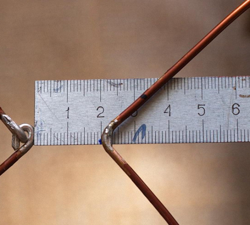
1) We need a piece of antenna cable, about 30 cm long.

2) Antenna connectors, the so-called F-connector and male-female connector.

F - connector and "father-mother"
3) Tools: a knife, wire cutters, a calculator and a tape measure (well, or a ruler).

Payment

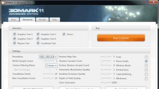
On the main page, we are looking for a tab - “CETV coverage map” and go to it.

CETV coverage map tab
Before us opened a map of coverage of digital television. We are looking for the nearest station for our city (I have Ulyanovsk, you fill in your city).


As you can see in my city, these are channel 56 - 754 MHz and channel 59 - 778 MHz.
Now we calculate the length of the antenna. I will not go into complex technical formulas and terms, we do not really need them. But to calculate the antenna, you need to divide 7500 by our frequencies.
THAT is: 7500/754=9.94 cm, this is for channel 56.

7500/778=9.64 cm, this is for channel 59.

Our antenna should be about 10 cm, and exactly - ((9.94 + 9.64) / 2 = 9.79 cm)
For your city, you also need to display the average length for your stations, if you have more than one in the city. In the video under the article, I calculated the antenna for Ulyanovsk, and for Kazan.
Manufacturing
1) We take a piece of antenna wire and first we attach an F-connector at the end. We simply strip the cable and screw on the connector so that the center wire is in the middle, and the screen (wires and foil were in the mount), detailed (useful).


2) Set aside a couple of centimeters from our connector (this will be a kind of indent), then measure 10 cm and cut off the unnecessary cable.

3) Now from these 10 cm, we need to remove the plastic insulator and remove the "screen" (foil and small wires). You don’t need to touch it further, leave the cable in the insulator.
4) All our antenna is ready. You can try to connect.

Connection
you need to catch good point reception in the apartment, and it is not always enough just to insert it into a TV or set-top box. I have such a place near the window, so I inserted an extension cord into the console and already inserted the antenna into the extension cord. So far, all this has not been improvised removed from me, for an example of work (therefore, the cable weighs), and the antenna itself is inserted into it.


Well, as you can see, all channels are working fine, and "first", and "Russia", and NTV, etc.

"First"


Thus, if you have 80 - 100 rubles, you can make an antenna for digital television (DVB-T2 standard) with your own hands, easily and simply.
Now video version
For those who do not show - - MANDATORY! There is a solution to the problem!
That's all, I think my article is very useful and relevant. Read our building site.
The main indicator of the quality of each antenna is its interaction with broadcast signal. This principle work underlies both purchased and home-made antennas. We suggest that you familiarize yourself with the recommendations on how to make an antenna for digital TV with your own hands.
Features of modern television
If we compare the modern television broadcast with the broadcast that was a few years ago, we can find certain differences. First of all, the UHF range is used for broadcasting. Thus, it is possible to significantly save money and signal reception by the antenna. In addition, in this case, the need for periodic maintenance of the antennas is also eliminated.
Also, there are many more television sensors than before, so most TV channels are available in almost all places in the country. To provide television broadcasting in habitable areas, low-power sensors are used.
In large cities, radio waves propagate differently. Because of a large number multi-storey buildings, the signal through them is weak. In addition, there is great amount television channels, for which one standard television antenna is not enough.
With the development of digital broadcasting, receiving channels has become even easier. These types of antennas are resistant to interference, phase or cable distortion, image clarity.
DIY simple digital antenna: device requirements
Since the broadcasting conditions have changed, the rules for operating modern antennas have changed:
1. One of the main parameters of a television antenna, in the form of a directivity factor and a protection factor, are not particularly important. To fight different kind interference using various electronic means.
2. The coefficient responsible for the gain of the antennas improves the signal, clears it of extraneous sounds and various kinds of interference.
3. One more thing important quality modern television antenna - range. Saving electrical parameters is carried out automatically, without additional human intervention.
4. The operating range of the television antenna should interact well with the cable that connects to the antenna.

5. In order to avoid the appearance of phase distortions, it is necessary to ensure decent antenna characteristics in the amplitude-frequency ratio.
The characteristics of the last three points are determined by the properties for receiving a television signal using an antenna. An antenna operating at one frequency is capable of receiving several wave channels. However, in order for them to be coordinated with the feeder, it is necessary to have OSS that strongly absorb signals.
Therefore, there are certain options digital antennas available for making at home. We invite you to familiarize yourself with them:
1. All-wave version of the antenna, such devices are frequency independent, they are cheap, very popular among consumers. One hour is enough to make such an antenna. Such an antenna is perfect for city apartments, but in locality, which is somewhat distant from television centers, such an antenna will work worse.
2. Speech therapy band version of the antenna - such an antenna picks up certain signals. It has a simple structure, is well suited for various operating ranges, does not change the parameters of the feeder. Differs in average technical parameters, great for country houses, cottages, apartments.

3. Z-shaped antenna, which is also called a zigzag. For the manufacture of such a design will require a lot of time and physical effort. Differs in wide receiving characteristics. With the help of such an antenna, it is possible to expand the range of reception of television channels.
To achieve an exact match between the antennas, it is necessary to lay the cable through the zero potential value.
Do-it-yourself digital TV antenna: reception characteristic
Vibratone antennas are capable of finding several more digital ones on one analog channel. Such devices receive wave channels. They are rarely used and are relevant for places remote from television towers.
Self-manufacturing satellite dish is a pointless process. Since in this process you will need to purchase a purchased tuner and head, and the mirror alignment must be very accurate, it is almost impossible to achieve it at home. You can only configure such an antenna yourself, but not its manufacture.
In order to make the above antenna options, you need to be very well versed in higher mathematics and electrodynamic processes. Among the main characteristics of the terms used in the manufacturing process of television antennas, we note:
1. KU - antenna power, which is determined in the ratio of the received antenna signal to its main petal.
2. KND - the relationship between the solid circle and the solid angle of the antenna lobes. If there are lobes of different sizes, they change in area.
3. KZD - the ratio between the signal received on the main lobe and total amount antenna power.
Please note that if the antenna is a band antenna, then the power is taken into account in relation to the useful signal.
Note that the first two terms are not necessarily interdependent. There are certain variants of antennas that have a high directivity, but unity or less gain. However, in a zigzag antenna, significant gain is coupled with a low level of directivity.

Do-it-yourself digital TV antenna: manufacturing technology
Each of the antenna elements, through which the current flows, giving a useful signal, must be connected to the other by soldering or welding. Any prefabricated assembly located on the street must be well fixed, since the destruction of the electronic contact on the street occurs faster than indoors.
Particular attention should be paid to zero potential. It is in these places that the nodes of voltage, electric current, with its highest power. For the manufacture of places with zero potential, one-piece bent metal is used.
For the manufacture of the braid or the central core, a coaxial cable is used, made of copper or an inexpensive alloy with anti-corrosion properties. For soldering the cable, a forty-volt soldering machine is used, with low-melting solders and flux paste.
Do-it-yourself outdoor digital antenna is made in such a way that all connections are resistant to moisture, temperature changes and other environmental influences.

For the manufacture of an all-wave antenna, two plates are required triangular shape, two slats, made of wood and enameled wire. At the same time, the size of the wire in diameter is practically not important, and the interval between their ends is about 2-3 cm. The interval between the plates on which the ends of the wire are located is 1 cm. Two metal plates can be replaced by a one-sided square-shaped fiberglass coated with foil. At the same time, copper triangles should be cut out on it.
The antenna width should be the same as the height. Cloths open at a right angle. In order to lay the cable to this antenna, you must follow a certain scheme. The cable braid is not soldered to the point indicating zero potential. She's just attached to her.
CHNA, which stretches inside the window by 150 cm, is able to receive most meter and DCM channels in any direction. The advantage of this antenna is that it has a wide channel reception interval. Therefore, such antennas are popular in large cities where there are various television centers. However, such an antenna has certain disadvantages - the KU of the antenna is single, and the KZD is zero. Therefore, in the presence of large interference, the antenna will be irrelevant.
It is possible to make other types of digital antennas with your own hands with a CNA, for example, a logarithmic spiral of two turns. This option The antenna is compact and easier to manufacture.
Essential digital antennas with hands from beer cans
For the manufacture of digital antenna with your own hands from the cable you will need beer cans. This version of the antenna right approach to its manufacture, it has good performance characteristics. In addition, such an antenna is quite simple to manufacture.
The principle of operation of such an antenna is based on an increase in the diameter of the arms on a conventional linear vibrator. In this case, the working band is expanded, while other properties do not change.
Beer cans in relation to their size are used as arms on a vibrator. At the same time, the expansion of the shoulders is unlimited. This version of a simple vibrator is used as a do-it-yourself indoor digital antenna for receiving television broadcasts by connecting directly with a cable.
If we dwell on the option of assembling an in-phase grating from a beer dipole, located vertically, with a step of half a wave, then it will be possible to improve the gain value of the antenna. Also, an amplifier from the antenna must be installed on this device, with the help of which the device is coordinated and tuned.

To enhance such an antenna, a KZD is added to it, a screen and a grid installed on it at the back, with an interval of half the grating. To install a beer antenna, you will need a dielectric mast, while the screen and mast are connected by a mechanical connection.
At the same time, about three or four rows are arranged on the grate. Two gratings are not capable of achieving much gain.
DIY UHF antenna for digital television
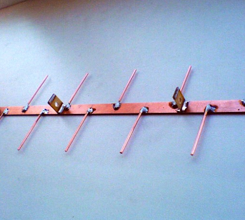
A log-periodic version of the antenna is called an assembled type antenna, which is connected to the halves on a linear dipole, the interval between them changes, in relation to geometric parameters progressions. There are configured and free lines. We propose to dwell on a longer and smoother version of the antenna.
For the manufacture of LPA, it is necessary to have any predetermined range. The higher the progression, the greater the gain of the antenna. This version of the antenna for operational and technical specifications is ideal for making at home.
The main principle of its normal functioning is to conduct correct calculations. With an increase in progressive indicators, the gain increases and the opening angle of the directivity decreases. This antenna is not required. additional screen. Since it does not depend on its general characteristics.

In the process of calculating a digital LP antenna, use the following recommendations:
- the second longest vibrator must have a margin of frequency power;
- then the longest dipole is calculated;
- after that, another specified frequency range is added.
If the shortest dipole leaves lines, then it is cut off, as it is needed on the antenna, only for calculations. The total length of the antenna will be about 40 cm.
The diameter of the lines on the antenna is about 7-16 mm. In this case, the interval between the location of the axes is 40 mm. The cable is not tied to the line by the external method, as this will adversely affect the technical properties of the antenna.
The outdoor antenna is fixed on the mast using the center of gravity. Otherwise, the antenna will constantly shake under the influence of the wind. However, the metal mast is not connected to the line in a straight line, since a dielectric mast must be provided at this place, the length of which is about 150 cm. As a dielectric material, a wooden beam, previously painted or varnished, can be used.
DIY digital antenna video:

The era of digital signals has arrived. All broadcasting TV companies began to work in a new format. Analog TVs live out their lives. They are still in working condition and are available in almost every family.
In order for the old models to successfully finalize their resource, and people can use them when watching digital broadcasting, it is enough to connect the DVB-T set-top box to the TV receiver and pick up TV wave signals with a special antenna.
Any home master is able not to buy an antenna in a store, but to make it with his own hands from improvised means for watching digital TV programs at home or in the country. The two most accessible designs are described in this article.
A bit of theory
The principle of operation of the antenna for digital packet television
Any television signal propagates in space from the emitters of the transmitting TV tower to the TV antenna as an electromagnetic wave of a sinusoidal shape with a high frequency, measured in megahertz.

When an electromagnetic wave passes through the surface of the receiving rays of the antenna, a voltage V is induced in it. Each half-wave of the sinusoid forms a potential difference with its own sign.
Under the action of an induced voltage applied to a closed receiving circuit of the input signal with resistance R, an electric current flows in the latter. It is amplified and processed by the digital TV circuitry and output to the screen and speakers as picture and sound quality.

For analog models of TV receivers, an intermediate link works between the antenna and the TV - DVB-T prefix, which decodes digital information of an electromagnetic wave into a normal form.
Vertical and horizontal polarization of digital TV signal
V television broadcasting state standards It is customary to radiate electromagnetic waves in only two planes:
- horizontal.

In this way, the transmitters direct the radiating signals.
And users simply need to rotate the receiving antenna in the desired plane to maximize the power potential removal.
Requirements for a digital packet television antenna
TV transmitters propagate their signal-waves to short distances, limited by the line-of-sight zone from the upper point of the transmitter of the TV tower. Their range rarely exceeds 60 km.
For such distances, it is sufficient to ensure the power of the emitted TV signal of a small value. But, the intensity of the electromagnetic wave at the end of the coverage area should form a normal voltage level at the receiving end.
A small potential difference, measured in fractions of a volt, is induced on the antenna. It creates currents with small amplitudes. It imposes high technical requirements to the installation and workmanship of all parts of the devices digital reception.
The design of the antenna must be:
- made carefully, with a good degree of accuracy, eliminating the loss of electrical signal power;
- directed strictly along the axis of the electromagnetic wave coming from the transmitting center;
- oriented according to the type of polarization;
- protected from extraneous interference signals of the same frequency coming from any sources: generators, radio transmitters, electric motors and other similar devices.
How to find out the initial data for calculating the antenna
The main parameter affecting the quality of the received digital signal, as can be seen from the explanatory first figure, is the length of the electromagnetic radiation wave. Under it, symmetrical arms of vibrators of various shapes are created, and the overall dimensions of the antenna are determined.
The wavelength λ in centimeters can be easily calculated using a simplified formula: λ=300/F. It is enough just to find the frequency of the received signal F in megahertz.
For this, we will use the Google search and ask it for a list of regional TV communication points for our area.
As an example, a fragment of the data table for the Vitebsk region is shown with a red rectangle highlighting the transmitting center in Ushachi.

The frequency of its wave is 626 megahertz, and the type of polarization is horizontal. These data are sufficient.
We perform the calculation: 300/626 \u003d 0.48 m. This is the length of the electromagnetic wave for the antenna being created.
We divide it in half and get 24 cm - the desired half-wave length.
The tension reaches its maximum value in the middle of this section - 12 cm. It is also called amplitude. Under this size, a whip antenna is made. It is usually expressed by the formula λ/4, where λ is the length of the electromagnetic wave.
The simplest TV antenna for digital television
It needs a cut coaxial cable with a wave impedance of 75 ohms and a plug for connecting an antenna. I managed to find a ready-made two-meter piece in an old stock.

From the free end with an ordinary knife, I cut off the outer shell. I take the length with a small margin: when adjusting, it is always easier to bite off a small segment.

Then I remove the shielding layer from this section of the cable.


The work is done. It remains to insert the plug socket into the connector on the TV signal set-top box and direct the bare wire of the inner core across the incoming electromagnetic wave, taking into account horizontal polarization.

The antenna should be placed directly on the windowsill or fixed on the glass, for example, with a piece of adhesive tape or tied to the blinds. Reflected signals and interference can be shielded with a strip of foil located at a small distance from the central core.
Such a design is done literally in ten minutes and does not require special material costs. It's worth trying it out. But, it is able to work in the zone of reliable signal reception. My building is shielded by a mountain and multi-storey building. The transmitting TV tower is located at a distance of 25 km. Under these conditions, the digital electromagnetic wave is reflected many times and is poorly received. I had to look for another technical solution.
And for you, on the topic of this design, I suggest watching the video of the owner Edokoff “How to make an antenna for digital TV”
Antenna Kharchenko at 626 MHz
To receive analog TV broadcasting signals of various wave frequency ranges, the zigzag design worked well for me before. broadband antenna, which do not require complex manufacturing.
I immediately remembered one of their effective varieties - the Kharchenko antenna. I decided to use its design for digital reception. The vibrators were made from a flat copper bar, but it is quite possible to get by with a round wire. This will make it easier to bend and align the ends.

How to determine the dimensions of a particular antenna
Online calculator
Let's use the all-knowing Google search. We write to command line: "Calculation of the Kharchenko antenna" and press Enter.

Choose any site you like and perform an online calculation. I went to the first one that opened. Here's what he gave me.

I presented all his data with a picture with the designation of the name of the size of the Kharchenko antenna.

Manufacture of antenna design details
I took the information provided as a basis, but did not accurately withstand all dimensions. I know from previous practice that the antenna works well in the broadband wave range. Therefore, the dimensions of the parts are just slightly overestimated. The half-wave of each harmonic of the sinusoid of the electromagnetic TV signal will fit into the shoulder of each vibrator and will be accepted by it.
Based on the selected data, I made blanks for the antenna.

Vibrator Design Features
The connection of the ends of the shank for the "eight" was created in the center at the bending stage. Soldered them with a soldering iron.

It was created for me according to the “Moment” principle, made with my own hands from old transformers, it has been working for two decades. I even soldered a copper wire of 2.5 squares to them in a thirty-degree frost. Works with transistors and microcircuits without burning them.
I plan to describe its design in the near future in a separate article on the site for those who also want to make it with their own hands. Follow the publications, subscribe to notifications.
Connecting the Antenna Cable to the Vibrator
I simply soldered the copper core and braid to the figure-eight metal from different sides in its center.

The cable was tied to a copper bar, bending it with a loop in the shape of a semi-square vibrator. In this way, the resistance of the cable and antenna is matched.
Shielding grid design
In fact, the Kharchenko antenna often works fine without signal shielding, but I decided to show its manufacture. For the base, I took a wooden block. I did not paint and impregnate with varnish: the structure will be used indoors.
I drilled holes in the back side of the bar for attaching the screen wires and inserted them, and then wedged them.

The result was a screen for Kharchenko's antenna. In principle, it can also be made of a different design: cut out of a piece of the frontal armor of a tank or cut out of food foil - it will work in about the same way.

WITH reverse side straps fixed the design of the vibrator with a cable.

The antenna is ready. It remains to install it on the window to work in vertical polarization.

When a television receiver is at a great distance from the transmitting generator, then the power of its signal gradually weakens. It can be enlarged with special electronic devices- amplifiers.
You just need to clearly see the difference between the signals received by the antenna, which can be:
- just weakened;
- contain high-frequency interference that distorts the shape of a digital sinusoid to the shape of some kind of "karyabola".
In both cases, the amplifier will fulfill its role and raise the power. Moreover, the TV will clearly perceive and show a weakened signal, and with an enhanced “karyabola”, playback problems will arise.
To eliminate such wave interference are called upon:
- h/h filters;
- screens.
They must be measured with an oscilloscope, and the ways of using various designs should be analyzed in each specific case individually. The antenna is not to blame.
It has always been difficult to get high-quality antennas - the Soviet industry practically did not produce them, so people themselves made them from improvised means. Today, the situation has not changed much - in stores you can only find lightweight aluminum Chinese crafts that do not show good results and rarely live more than a year. What to do if you like to watch TV as well good reception No? The answer is simple -With free time and a pair of skillful hands, anyone can handle this.
More recently, Russia has analog television, but now almost the entire country has switched to digital broadcasting. Its main difference is that it works in the decimeter range.
Create a homemade antenna for digital range possible at home
This was done for reasons of economy and safety - care for transmitting antenna-feeder stations is actually not required, their maintenance is minimized, and harm from contact with powerful transmitters for masters is minimal. But such stations have one serious drawback - low power. And if in a big city the signal can often be caught even for a segment copper wire reception may be difficult when away from the transmitter. If you live outside the city, in remote areas or villages, you will have to assemble your own antenna and take it outside to catch the desired signal.
Attention:signal problems can occur even in the city center. Decimeter waves are practically not muffled by other sources, but are reflected from thick reinforced concrete walls. In modern high-rise buildings there are many places where they are completely attenuated, not reaching the TV receiver.
It is also worth noting that DVB-T2 ( new standard television) offers a fairly constant, but weak signal. With a noise level one and a half to two units above the norm, the TV reproduces the air quite clearly, but as soon as the noise exceeds 2 dB, the signal disappears completely. Digital television is not sensitive to electromagnetic interference- it is not knocked down by a working refrigerator or microwave. But if there is a mismatch anywhere in the system, then the picture stops or falls apart. qualitysolve this problem, but in some cases, it will have to be taken out onto the street or onto the roof.
Basic requirements for antennas
The television standards in force in the USSR do not fit modern realities - the protective and directional coefficients today have practically no effect on signals. The air in the cities is clogged and contains a lot of dirt, so you should not pay attention to these coefficients. You are guaranteed to receive interference on any antenna, so you do not need to achieve a reduction in DRR AND NPV. It is better to improve the gain of the antenna so that it receives a large range of air and selects the desired stream, rather than focusing on a specific signal. The processor of the set-top box or TV itself will isolate the necessary signals and create a normal picture.
 Classic Polish antenna with amplifier
 So, Experienced engineers recommend building band antennas. They must be correctly timed by taking signals the classic way, and not due to engineering "optimizations" and traps. Perfect option— the device fully complies with theoretical calculations and geometry. Also, the constructed antenna must be consistent with the cable at operating ranges without the use of matching devices. In this case, it is best to create a frequency response smooth and even, since phase distortions appear when the amplitude-frequency characteristic fails or jumps.
Attention: analog antennas with ferrite USS, which provide full-fledged reception of the old signal, practically do not work with DVB. It is necessary to build a “digital” antenna.
In the article we will analyze modern types antennas working with new digital broadcasting.
Antenna types
What do-it-yourself digital TV antennas can be collected at home? There are three most common options:
- All-wave, or as radio amateurs call it, is frequency independent. It assembles very quickly, does not require high knowledge or specialized tools. Well suited for the private sector, villages, summer cottages - where the air is not littered with garbage, but not far from the transmitter.
- log-periodic range. It has a simple design, well receives a signal at a close and medium distance from the transmitter. It can be used as a remote if the transmitter is located far away, or as a home wall antenna.
- Z-antenna and its variations. Many radio amateurs are familiar with meter-long "zashkas" - they are quite large and require a lot of effort to assemble. But in the decimeter range, they are quite compact and do their job well.
The nuances of construction
If you want to build a quality antenna, you must master the art of soldering. You can not twist the contacts and guides - during operation they are oxidized, the signal is lost, the picture quality deteriorates. Therefore, all connections are soldered.
 Such connections are not allowed - be sure to solder them
 You also need to deal with zero-potential points where currents occur even when there is no voltage. Experts recommend making them from a single piece of metal, without using welding at all. Even high-quality welded pieces can make noise at the boundary values, while a solid strip will “pull out” the signal.
Also when creating homemade antenna for digital TV you need to deal with soldering cables. Today, copper is practically not used for braiding, since it is expensive and quickly oxidizes. Modern braid is made of steel, which is not afraid of corrosion, but it is very poorly soldered. It must not be overheated or squeezed. Use 36-40 watt soldering irons, flux and light solder to connect. Dip the winding well in the flux and apply solder - it is perfectly taken with this method of application.
All Wave Antenna
The all-wave antenna has quite simple design. It consists of triangles, copper wire and wooden slats. You can study the design in more detail in the picture - it does not represent something supernatural.
The thickness of the wire can be any, the distance between adjacent wires is 25-30 mm, the distance between the plates is no more than 10 mm. The design can be improved by abandoning the plates and using textolite. It needs to be given the appropriate shape or just remove the copper foil in the shape of a triangle.
The remaining proportions are standard - the height of the device must match the width, the plates diverge at a right angle. Zero potential is on the extreme line home tv antenna , just at the intersection of the cable with the vertical guide. To avoid quality losses, the cable must be pulled to it with a tie - this is enough for coordination. Such an antenna, hung out on the street or directed at a window, receives virtually the entire frequency range, but has a small dip, so you need to set the correct angle when fixing the antenna.
By the way, this design can be upgraded with ordinary aluminum cans from beer and cola. The principle of its operation is as follows: with an increase in the span of the shoulders, the working band expands, although the rest of the indicators remain within the original limits. The Nadenenko dipole, often used in military developments, works on the same principle. The aluminum cans fit perfectly in shape and size, creating vibrator arms in the decimeter range.
 Double Can Antenna for TV
 You can create a simple canned antenna by simply soldering two cans to a cable. This do-it-yourself indoor TV antenna suitable for viewing channels at a small to medium distance from transmitters. Nothing needs to be coordinated in this scheme, especially if the cable length is less than 2 meters.
You can complicate the design by assembling a full-fledged lattice from eight cans and using an amplifier from an ordinary Polish antenna. This design is great for hanging outdoors in areas remote from the transmitter. To enhance the signal, a metal mesh can be placed behind the structure.
Z antenna
There are complex Z-antenna designs with multiple loops, but in most cases they are not needed. You can easily assemble a structure from ordinary copper wire 3 mm thick. If you don't have one, then just buy a single-core copper wire 3 mm long 120 mm - this is quite enough for you to work. This design consists of two segments. We bend the wire according to the following scheme:
- The starting section is 14 centimeters long. Its edge is bent into a loop to connect with the last one (loop 1 cm, total length of the first piece - 13 cm).
- The second piece is bent at 90 degrees (it is better to bend with pliers to keep the angles). Its length is 14 cm.
- The third piece is bent at 90 degrees parallel to the first, length 14 cm.
- The fourth and fifth pieces are 13 cm each, the bend does not reach the loop by 2 cm.
- The sixth and seventh pieces are 14 cm each, bent at 90 degrees.
- Eighth - returns to the loop, length 14.1 cm goes to a new loop.
Next, you need to clean the two loops well and solder them. The opposite corner is also cleared. The cable contacts are soldered to them - to one central, to the second - a braid. There is no difference to which contact to solder.. It is advisable to insulate the soldered places, for this you can use sealants or hot melt adhesive. The ends of the cable are soldered to the plug and also insulated with cambric.
 You can assemble such an antenna in half an hour
 To avoid displacement of the segments, the edges can be reinforced. To do this, take an ordinary plastic cap from a five-liter bottle, cut 4 slots in it so that the wire sinks to the base. Cut the fifth hole for the cable. Then put the antenna into the cover (having previously checked the quality and reliability of the soldering), and fill it with hot glue. The resulting design will be almost eternal - it is able to take steady signal up to 10 km from the source.
So you already know what can be used instead of a TV antenna. In fact, the designs are much larger than those that we have described, but even these will be enough for you. If you live far from the source of the signal, then you will need amplifying antennas - you can get by with the classic “polka” with gain. Well, if everything is bad with the ether, then use satellites.