Almost every novice radio amateur, and not only, had a desire collect color music prefix or a running fire to diversify listening to music in the evening or on holidays. In this article, we will focus on a simple color music set-top box, assembled on LEDs, which even a novice radio amateur can collect.
1. The principle of operation of color music consoles.
The work of color music consoles ( CMP, CMU or SDU) is based on frequency division of the spectrum of an audio signal with its subsequent transmission through separate channels low, middle and high frequencies, where each of the channels controls its own light source, the brightness of which is determined by the oscillations of the sound signal. The end result of the work of the set-top box is to obtain a color scheme corresponding to the music being played.
To obtain the full gamut of colors and the maximum number of color shades, at least three colors are used in color music consoles:

The division of the frequency spectrum of the audio signal occurs using LC- and RC filters, where each filter is tuned to its own relatively narrow frequency band and only passes through itself the vibrations of this section of the audio range:
1
. Low pass filter(LPF) transmits oscillations with a frequency of up to 300 Hz and the color of its light source is selected in red;
2
. Mid Pass Filter(FSF) transmits 250 - 2500 Hz and the color of its light source is selected green or yellow;
3
. High pass filter(HPF) transmits from 2500 Hz and above, and the color of its light source is selected blue.

There are no fundamental rules for choosing the bandwidth or the color of the glow of the lamps, so every radio amateur can use colors based on the characteristics of his perception of color, and also change the number of channels and bandwidth at his own discretion.
2. Schematic diagram of a color music set-top box.
The figure below shows a diagram of a simple four-channel color music set-top box, assembled on LEDs. The set-top box consists of an input signal amplifier, four channels and a power supply unit that supplies power to the set-top box from the AC mains.

An audio signal is applied to the contacts PC, OK and General connector X1, and through resistors R1 and R2 falls on a variable resistor R3, which is the input level control. From the middle terminal of the variable resistor R3 beep through the capacitor C1 and resistor R4 enters the input of a pre-amplifier assembled on transistors VT1 and VT2... The use of an amplifier made it possible to use the set-top box with almost any audio signal source.
From the output of the amplifier, the audio signal is fed to the upper terminals of the trimming resistors R7,R10, R14, R18, which are the load of the amplifier and perform the function of adjusting (tuning) the input signal separately for each channel, and also set the desired brightness of the channel LEDs. From the middle terminals of the trimming resistors, the audio signal is fed to the inputs of four channels, each of which operates in its own band of the audio range. Schematically, all channels are made the same and differ only in RC filters.
Per channel higher R7.
Channel bandpass filter formed by a capacitor C2 and only passes the high-frequency spectrum of the audio signal. Low and middle frequencies do not pass through the filter, since the resistance of the capacitor for these frequencies is high.

Passing the capacitor, the high frequency signal is detected by the diode VD1 and fed to the base of the transistor VT3... The negative voltage appearing at the base of the transistor opens it, and a group of blue LEDs HL1 — HL6 included in its collector circuit are ignited. And the greater the amplitude of the input signal, the more the transistor opens, the brighter the LEDs light up. To limit the maximum current through the LEDs, resistors are connected in series with them R8 and R9... If these resistors are missing, the LEDs may be damaged.
Per channel middle frequency signal is supplied from the middle terminal of the resistor R10.
The channel bandpass filter is formed by the contour С3R11С4, which for low and high frequencies has significant resistance, therefore, on the base of the transistor VT4 only mid-frequency vibrations are received. LEDs are included in the collector circuit of the transistor HL7 – HL12 Green colour.
Per channel low frequency signal is fed from the middle terminal of the resistor R18.
The channel filter is formed by a contour С6R19С7, which attenuates the signals of medium and high frequencies and therefore to the base of the transistor VT6 only low frequency vibrations are received. The channel is loaded by LEDs HL19 – HL24 Red.
For a variety of colors, a channel has been added to the color music prefix yellow colors. The channel filter is formed by a contour R15C5 and operates in the frequency range closer to low frequencies. The input signal to the filter comes from a resistor R14.
The color music console is powered by constant voltage 9B... The set-top box power supply consists of a transformer T1, diode bridge made on diodes VD5 – VD8, microcircuit voltage stabilizer DA1 type KREN5, resistor R22 and two oxide capacitors C8 and C9.
AC voltage rectified by a diode bridge is smoothed by an oxide capacitor C8 and goes to the voltage stabilizer KREN5. From the conclusion 3 of the microcircuit, a stabilized voltage of 9V is supplied to the set-top box circuit.
To obtain an output voltage of 9V between the negative bus of the power supply and the terminal 2 microcircuit included resistor R22... By changing the value of the resistance of this resistor, they achieve the desired output voltage at the output 3 microcircuits.
3. Details.
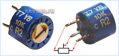
Any fixed resistors with a power of 0.25 - 0.125 W can be used in the set-top box. The figure below shows the values of resistors in which colored stripes are used to indicate the value of resistance:

Variable resistor R3 and trimming resistors R7, R10, R14, R18 of any type, if only they fit the size of the printed circuit board. In the author's version of the design, a domestic variable resistor of the SP3-4VM type was used, and trimming resistors were imported.
Fixed capacitors can be of any type, and are designed for an operating voltage of at least 16 V. If you have difficulty acquiring a 0.3 μF capacitor C7, it can be made up of two 0.22 μF and 0.1 μF capacitors connected in parallel.
Oxide capacitors C1 and C6 must have an operating voltage of at least 10 V, capacitor C9 at least 16 V, and capacitor C8 at least 25 V.

Oxide capacitors C1, C6, C8 and C9 have polarity, therefore, when mounting on a breadboard or printed circuit board, this must be taken into account: for Soviet-made capacitors on the case they indicate a positive terminal, for modern domestic and imported capacitors they indicate a negative terminal.

Diodes VD1 - VD4 any of the D9 series. A colored strip is applied to the diode body from the anode side, defining the letter of the diode.

As a rectifier, assembled on VD5 - VD8 diodes, a ready-made miniature diode bridge is used, designed for a voltage of 50V and a current of at least 200 mA.

If you use rectifier diodes instead of a ready-made bridge, you will have to slightly correct the printed circuit board, or even move the diode bridge outside the main board of the set-top box and assemble it on a separate small board.
For self-assembly of the bridge, the diodes are taken with the same parameters as the factory bridge. Any rectifier diodes from the KD105, KD106, KD208, KD209, KD221, D229, KD204, KD205, 1N4001 - 1N4007 series are also suitable. If you use diodes from the KD209 or 1N4001 - 1N4007 series, the bridge can be assembled directly from the printed wiring side directly on the contact pads of the board.
LEDs are conventional with yellow, red, blue and green glow colors. Each channel uses 6 pieces:

Transistors VT1 and VT2 from the KT361 series with any letter index.

Transistors VT3, VT4, VT5, VT6 from the KT502 series with any letter index.

Voltage stabilizer type KREN5A with any letter index (imported analogue 7805). If you use nine-volt KREN8A or KREN8G (imported analogue 7809), then the resistor R22 is not installed. Instead of a resistor, a jumper is installed on the board, which connects the middle terminal of the microcircuit with the negative bus, or this resistor is not provided at all in the manufacture of the board.

To connect the set-top box with a sound signal source, a jack-type connector for three contacts is used. The cable is taken from a computer mouse.

Power transformer - ready-made or home-made with a power of at least 5 W with a voltage on the secondary winding of 12 - 15 V at a load current of 200 mA.
In addition to the article, watch the first part of the video, which shows the initial stage of assembling a color music set-top box.
This concludes the first part.
If you are tempted to make color music on LEDs, then select parts and be sure to check the health of diodes and transistors, for example,. And then we will make the final assembly and adjustment of the color music console.
Good luck!
Literature:
1. I. Andrianov "Prefixes for radio receivers".
2. Radio 1990 №8, B. Sergeev "Simple color music prefixes".
3. Operation manual for the radio designer "Start".
Such LED color music is suitable for those who listen to music on a computer. It can be placed inside the case and it will be illuminated to the beat of the music.
The color music scheme is very simple and does not present any difficulties.
 Required components:
1.4 LEDs (any color) 3mm
2.P2 plug
3.2 position switch
4. Bipolar transistor TIP31
5. The box (if needed) can be placed directly in the computer case
6. Soldering iron
7. Cable
 We connect 4 LEDs to +12 V of the computer, the anode is connected to a 2-position switch, which in turn is connected to the TIP31 bipolar transistor. We connect the two unused ends of the transistor directly to the terminals of the plug for headphones or speakers P2.
We install all assembled components in a box (box), or directly into a computer case - it's up to everyone at their discretion. We made holes for the LEDs, switch and plug.

Installation of LED color music in a box
Let's connect LEDs, transistor and switch
1 of 2

Connecting LEDs

General assembled view with transistors
Further - the most interesting. It is necessary to solder the LEDs together, the transistor and the switch. From the photographs it is clear without words. The only thing we had to do was to select the length of the conductors so that they fit into the box.
The common minus from the LEDs is connected to the middle contact of the switch. From the switch, one of the positions is connected to the middle pin of the transistor, connect the second position according to the color music scheme that we presented above.
Wiring to plug P2
The final stage
1 of 2

Installation of a diode color music circuit

Soldered plug
If we disassemble the plug from the headphones, then inside we can see three connectors - left and right channels, ground. We connect one of the channels to the left pin of the Tip31 transistor. If P2 is connected through the left channel and it does not "beat" the computer output, then our circuit will not work. Therefore, immediately define correctly or experiment. Ground (usually the long connector) should be connected to the right pin of the transistor.
One of the switch pins should be connected to ground from the transistor. With this connection, the LEDs will start blinking if there is any signal at the output. If there is no signal from the P2 connector, if the signal is from the other side, then they will glow constantly.
We mount everything in a box, connect it and check its functionality.
We all want a holiday from time to time. Sometimes you want to feel sad or to experience other emotions. The easiest and most effective way to achieve the desired result is to listen to music. But music alone is often not enough - you need visualization of the sound stream, special effects. In other words, we need color music (or light music as it is sometimes called). But where can you get it if such equipment in specialized stores is not cheap? Do it yourself, of course. All that is needed for this is a computer (or a separate power supply), several meters of LED RGB strip with a power consumption of 12V, a USB prototype board (AVR-USB-MEGA16 is perhaps the cheapest and simplest option), as well as a circuit diagram what and where to connect.
A little about the tape
Before moving on to the work itself, it is necessary to determine what exactly this 12V RGB LED strip is. And it is a simple, but at the same time very ingenious invention.
LEDs have been known for decades, but thanks to innovative developments, they have become a truly universal solution to many problems in the field of electronics. They are now used everywhere - as indicators in household appliances, independently in the form of an energy-saving lamp, in the space industry, as well as in the field of special effects. The latter includes color music. When three types of LEDs - Red, Green and Blue - are combined on one strip, the result is an RGB LED strip. Modern RGB diodes have a miniature controller. This allows them to emit all three colors.
A special feature of this tape is that all diodes are grouped and connected in a common chain. controlled by a common controller (it may also be a computer if connected via USB, or a special power supply unit with a control panel for stand-alone modifications). All this allows you to create an almost endless tape with a minimum of wires. Its thickness can literally reach a few millimeters (if you do not take into account the options with rubber or silicone protection from physical damage, moisture and temperature). Prior to the invention of this type of microcontroller, the simplest model had at least three wires. And the higher the functionality of such garlands, the more wires there were. In Western culture, the phrase "unravel the garland" has long become a household name for all long, tedious and extremely confusing cases. And now it has ceased to be a problem (also because the LED strip is prudently wound on a special small drum).
What we need?

DIY color music from GE60RGB2811C tape
Ideally, for organizing color music with our own hands, a ready-made LED strip powered by the USB port of a computer is suitable for us. All we need is to download the required application for the same computer, set up file associations with the desired audio player, and enjoy the result. But this is if we are very lucky, and if we have the money to buy it all. Otherwise, everything looks a little more complicated.
In the sale of electronic components stores there are LED strips of various lengths and powers, but we only need 12v. It is the best option for connecting to a computer via USB. So, for example, you can find the model GE60RGB2811C, which is a series of 300 RGB LEDs connected. One of the advantages of any such tape is that it can be cut as convenient as anyone - any length. All that is needed after that is to connect the contacts so that the electrical circuit is not open, and the circuit is integral (this must be done).

Color music setting scheme
We may also need a prototype board for USB connection. The most popular, cheap, but functional option for connection is the AVR-USB-MEGA16 model for USB 1.1. This USB version is considered to be somewhat outdated. transmits a signal to the LEDs at a speed of 8 milliseconds, which is too slow for modern technology, but since the human eye perceives this speed as a "blink of an eye", then it is quite suitable for us.

If we omit most of the most complex technical subtleties and nuances, then all that a diagram of such a connection requires from us is to take a tape of the required length, free and clean the contacts on one side, connect and solder them to the output on the breadboard (the symbols are indicated on the board itself, what connector and what is it for) and, in fact, that's it. For the full length of the 12v tape, there may not be enough power, so you can power them from an old computer power supply (this will require a parallel connection), or simply cut the tape. The sound with just this option will come from the computer speakers. For the electronics savvy, we recommend connecting a microphone amplifier and a small "buzzer speaker" directly to the AVR-USB-MEGA16.

Diagram of fastening tape contacts to a USB cable from a smartphone
If it was not possible to get this board, then in the most extreme case, the connection can be made via a 12V LED strip to a USB cable from a smartphone or tablet computer (the scheme for setting up color music with your own hands allows this). It is only important to make sure that the cord will give the required 5 watts of power. At the end of all these manipulations, we install the SLP program (or write all the steps in a txt file, if knowledge in programming allows and the scheme and algorithm of all actions are clear), select the desired mode (by the number of diodes), and enjoy the work done by our own hands.
Output
Color music is not an essential item, but it makes our life much more interesting, and not only because we can now look at the flashing colored lights that light up and go out to the beat of our favorite melody. No, we're talking about something else. Having made something similar with their own hands, and not buying in a store, everyone will feel a surge of strength from the satisfaction inherent in every master and creator, and the realization that he is also worth something. But as a matter of fact, the color music is installed, it blinks and pleases the eye with minimal costs and maximum pleasure - what else is needed? ..
 Lighting in the kitchen of a small apartment
 We select lamps for mirrors, possible options
 Airplane chandelier for children's room
Most people listen to music with great pleasure using various equipment. Often there is a desire to enhance its positive impact. One of these methods is color music on diodes, made in the form of special attachments. With the help of diodes, sound effects take on a completely different color, having a positive impact on the emotional state of the listeners. Such electronic equipment is usually purchased ready-made, but if there is a circuit, certain knowledge and skills, it may well be made by hand.
The principle of operation of color music on LEDs
The basis of the work of each scheme of a color-musical installation is a physical principle associated with the frequency transformation of music. Then it is transmitted through separate channels and controls the connected lighting devices. This chain links basic musical characteristics to color elements that match and work in mutual connection. This principle serves as the basis for all electronic circuits from the field of color music, including those created independently.
Most often, the color scheme includes at least three different colors, for example, red, green and blue. There are many combinations that can be created by mixing them, so if the circuit is assembled well, it will definitely give the desired effect. To achieve this, the signal is split and operated at low, mid and high frequencies. Separation is carried out using special filters LC and RC, installed in a common chain of the LED color music system.
There are certain parameters used when tuning filters that operate in their own narrow frequency band and transmit oscillations only in this segment of the sound range:
- LPF - low-pass filters. The frequency of vibrations passing through them reaches 300 Hz, and the light source should be red.
- FSF - mid-frequency filters. They are capable of transmitting vibrations with a frequency of 250 to 2500 Hz, the color of the light source is yellow or green.
- HPF - high-pass filters that transmit more than 2500 Hz and work in conjunction with a blue light source.
The divided frequencies of the circuit overlap each other slightly, which makes it possible to obtain a variety of color shades in the process. The primary colors listed above are not of fundamental importance, it is quite possible to replace them with others - the most suitable for a particular situation. In some cases, the end result significantly exceeds expectations, thanks to the use of non-standard colors.
Simple and complex schemes
Acquaintance with color music opens the simplest scheme. As a rule, such devices use the minimum number of elements - only one LED, and one resistor and one transistor each. Power is supplied through a constant current source of 6-12V.

In the assembled form, the LED color music is an amplifier stage, complemented by a common emitter. The main effect is provided by a signal with varying amplitude and frequency arriving at the base. When the frequency exceeds the set threshold value, the transistor opens. At this point, the LED receives power and immediately lights up.
Such a simple color music can be assembled with an application that requires an appropriate transistor. A significant drawback of this assembly is the direct relationship between the sound level and the blinking frequency of the LED lamps. That is, the system will work most efficiently with the support of only one, the most appropriate sound level. At a lower volume, the blinking will occur less frequently, and at a high sound level, the light will become constant.
This disadvantage is easily removed by a three-channel audio converter, which is used in more complex circuits. In this case, a 9 volt power supply will be required, which ensures the normal glow of the lamps in the corresponding channels.

To assemble a circuit of three amplification stages, you need to stock up on KT315 transistors or their analogs KT3102. LEDs of different colors serve as a load. The amplifying function is performed by a step-down transformer, the LED flashes are controlled by resistors, and the above filters pass different frequencies through them.
This LED color scheme can be further improved. First of all, this concerns the brightness of the glow, added by the inclusion of small 12 volt incandescent bulbs in the chain. In this case, the circuit is supplemented with control thyristors, and the entire device is powered through a transformer.
Using LED strips
Color music circuit with RGB LED strip operates on 12 volts. It combines the main parameters of the usual options in the best way. This device can work in different modes - as a lighting device or color music accompaniment.

The inclusion of the color music mode is carried out using a microphone, in a non-contact way. In case of switching to lighting mode, all available LEDs are simultaneously activated at full power. The transition from one state to another is performed by a special switch, for which a separate board is provided.
The procedure for this scheme is as follows:
- The main signal comes through a microphone, which converts the sound vibrations of the phonogram. Since the strength of the received signal entering the color-musical scheme is insignificant, it must be amplified. For this purpose, a transistor or a special amplifier is used.
- Next, an automatic regulator is launched, which keeps the sound vibrations within the established limits. At the same time, the sound is being prepared for further processing.
- With the help of built-in filters, the signal is divided into three components, for each of which there is a separate frequency range.
- At the end of all actions, the current signal is amplified after its preliminary preparation using transistors operating in the key mode.
Main parts and components
Before making equipment for color music with your own hands, you must prepare all the parts and components in advance. In the circuit, you should use only fixed resistors with a power range of 0.125-0.25 ohms. The housings of the circuit elements are marked with special stripes indicating the resistance value. Additionally, trimming resistors R7, R10, R14, R18 are used. They can be of different types, but the only requirement for them is the ability to mount on the board used for assembly.


Capacitors are designed for operating voltages of 16V and above. Any type of these devices can also be used in color music. If it is impossible to find a capacitor with the required parameters, it is allowed to connect two others in parallel, with smaller capacities, which add up to the required indicators.
The made color-musical circuit cannot do without a diode bridge. It is usually rated for operating currents up to 200 mA and 50 volts. In the absence of a ready-made device, you can use several separately taken rectifier diodes and mount them for convenience on a separate small board.

The primary colors of the LEDs are red, green and blue. Their total number is determined on the basis of one channel - 6 pieces. Standard transistors with any designation index will be needed. The voltage regulator with the article number 7805 is designed for 5V, and the device for 9V has the designation 7809. With experience, color music is assembled on the Arduino board and LEDs.
The connection of the music center with color music is carried out by various types of connectors with three contacts. The last part of the assembly is the transformer, which must have the most suitable voltage parameters.
Color music equipment in the car
Color music equipment is used not only at home. Many car owners install them in conjunction with radio tape recorders. If necessary, this system works as a lighting inside the cabin. For a device of this type of lighting, LEDs are also used, placed on the ceiling in the "Starry sky" configuration. This option is often used not only in cars, but also in the construction of suspended ceilings in apartments and private houses.

This layout, when solving the problem of how to make color music from LEDs, can be used in different versions. First of all, it is a uniform distribution of LEDs in a certain configuration or in any form. The bulbs used in the circuit can have different luminescence powers. That is, the stars simulated by LEDs are bright and dim. The effectiveness of the backlighting largely depends on the background of the ceiling covering the interior of a car or apartment.
If you install a LED color music system with your own hands, you will have to drag the ceiling during the installation process. In this regard, it is necessary to carefully select the necessary parts and then carefully assemble them into a single whole. In case of any violations, you will have to disassemble the interior cover and correct errors. Therefore, at the end of the assembly, it is imperative to check the operability of the installed equipment.
After the color music is assembled, the LEDs are inserted into the holes in the ceiling and fixed on the back with glue. It is also necessary to think in advance about the reliable fastening of the voltage stabilizer and the switch.
It is difficult to find such a person who would not like to listen to music. To satisfy this desire, high-quality music centers, speakers and other devices are purchased. For even more pleasure, many are thinking about creating special color effects that can decorate any sound and create a romantic atmosphere on a date or a fun mood in the process of organizing a holiday party. Color music, as well as music centers, can be purchased, or you can do it yourself. The best option is to make a do-it-yourself color music on LEDs according to one of the proposed schemes.
Benefits of LED products
The modern electronics market presents a wide variety of LED strips that have a wide variety of color effects. With their help, you can create high-quality point lighting, it is possible to make light music with blinking or blurry effects.
Unlike conventional light bulbs, LEDs are characterized by a large number of positive characteristics. Among the main advantages of LED strips are:
- wide and varied colors;
- transfer of saturated colors;
- different design options - rulers, modules, discrete elements, RGB tapes;
- high response speed;
- the minimum amount of energy consumed.
The ribbons can be used at home, in clubs and cafes, and showcases can be effectively illuminated. This article will describe in more detail the version of LED color music for ordinary home use.
Simple circuit with one luminaire
To begin with, it is worth studying a simple color music scheme. It is a device that runs on a single LED, transistor and resistor. Power for such color music can be supplied from a constant current source with a voltage of 6-12 volts. The device operates on the principle of a common emitter amplifier stage. The impact in the form of a signal and amplitude varying in frequency comes to the main base. As soon as the oscillation frequency exceeds a certain threshold value, the transistor opens and the LED immediately flashes.

This scheme of simple color music on LEDs has one drawback - the rate of blinking of the LED depends entirely on the level of the sound signal produced. In other words, the light effect will be activated only at a certain level of the volume produced by the musical center. With a decrease in the intensity of the sound, the glow will be constant with occasional winks.
Single color ribbon scheme
This transistor-based color music is assembled using an LED strip in the load. To organize such color music, you will need to increase the power supply to 12 V, find and install a transistor with a maximum collector current that exceeds the load current, and you will also need to recalculate the total value of the resistor. Such color music is quite simple, made on one single-color LED strip and is ideal for novice radio amateurs. You can assemble it without any problems at home.
Simple three-channel circuit
To get color music, devoid of all the disadvantages listed above, it is worth using a special three-channel sound transducer. This circuit is powered by an LED strip with a constant voltage of 9 V and is able to effectively illuminate one or two LEDs in each channel. Among the main structural elements that characterize such a color-musical scheme, one can note:
- three independent amplifying stages, which are assembled on transistors of the KT315 (KT3102) category;
- LEDs of different colors are included in the load of transistors;
- for the pre-amplification element, a small mains transformer of a step-down character can be used.

The input signal is fed to the secondary winding of the transformer, which, in turn, performs two main functions - it decouples two devices at a galvanic level, and also amplifies the sound from the main line output. After that, the signal goes to three parallel-located and connected filters, assembled on the basis of RC-circuits. They operate on an individual frequency band, which directly depends on the value of the capacitor and resistor.
Color music with RGB tape
This set-top box circuit operates from 12 volts and is ideal for installation on a car. Such color music optimally combines the main functions of the previously considered schemes and is able to work both in the lamp mode and in color music. The second mode is achieved due to the special contactless control of RGB tape by means of a microphone. As for the luminaire mode, it is based on the simultaneous activation of the green, red and blue LEDs at full power. The choice of the mode can be carried out by means of a special switch, which is located on a special board.
To understand how this set-top box works, it is worth studying its sequence of actions. The main signal source here is a microphone, which converts sound vibrations emanating from a phonogram. The received signal is insignificant, therefore it requires amplification. This can be achieved by using a transistor or a special operational amplifier. After that, the automatic AGC level controller is started. It effectively keeps the vibrations of the sound within reasonable limits and prepares it for further processing. Built-in filters divide the signal into three parts, each of which operates in one specific frequency range. Finally, you just need to amplify the previously prepared current signal. For this purpose, special transistors are used that operate in a key mode.

Purchase of a ready-made CMU
If you do not want to make a color music for use at home, you can purchase a CMU, that is, a color music installation. This is a ready-made functional solution, which includes a controller. It will process the sound, transforming it into a light and music visual presentation. In the process of light reproduction, its intensity and color scheme will change, thereby creating the effect of a real disco. Also, the CMU device includes a panel with built-in diodes.
These devices can be based on spectral frequency decomposition, where each of them will correspond to a certain color scheme or predefined adjustments with a variety of effects and their alternation. You can configure them using the supplied remote control.
Important! Modern CMUs are very easy to install and configure. It is the perfect solution for organizing a home party or disco.
Conclusion
There are a lot of schemes for self-implementation of color music installations. You can choose a fairly simple option, where the color of the RGB tape will simply change, to quite complex ones, which in the process of work will create a large number of various effects, overflows and fading. In direct dependence on the skills, you can choose and execute the appropriate option. It is enough to work a little and create something truly unique, it will be lighting equipment, delighting with overflows of various color shades. Also, do not forget that there is always an opportunity to buy a ready-made color music solution and fill your home with color shades and joy.