So, imagine this situation: in the evening you decided to watch your favorite TV program, and suddenly the TV stopped showing. Or another case: you have arrived at the dacha, have already prepared for the rest and again the same situation - not a single channel is working. What to do in this case? The answer is simple - you need to make an antenna for the TV with your own hands, because most likely the cause of the breakdown is in this particular device. Next, we will consider the simplest options for creating, which will require a minimum of available tools and time.
Idea # 1 - Beer cans are in use!
This version of a homemade television antenna is the simplest and fastest to manufacture. The maximum number of channels that will be at your disposal is 7, but this figure may vary slightly depending on the region.
To make an antenna for a TV from beer cans, you will need the following materials:
- 2 small screws, also called "bugs";
- 2 prepared beer cans (empty, washed and dried);
- from 3 to 5 meters of television cable (can be taken from a failed device);
- soldering iron and tin (for better fixing of contacts), the presence is optional;
- screwdriver;
- wooden tremp;
- electrical tape or tape.
It will not be a problem to find all the materials in the house, therefore, having prepared them, we immediately get down to business.
In order to make a homemade antenna from cans, you need to follow these steps:
- We are preparing the cable. First, at a distance of 10 cm from the edge, you need to make an incision and remove part of the top layer of insulation. Having opened access to the screen, we fold it into one turn. After that, we cut off the middle insulating layer, exposing the thin copper core of the cable. As for the other end of the conductor, there should be a regular plug.
- We prepare banks. There will also be no difficulties with capacities that act as a signal receiver. First, you need to find the optimal size of the beer cans. It is better to use liter, but if there are none, containers with a volume of 0.5 and 0.75 liters will do a good job.
- We summarize contacts. At this stage, the twisted cable shield is attached to one jar, and the copper core itself to the other. Fixation is carried out with bedbugs using a screwdriver. In order to make the picture quality on the TV screen higher (signal transmission quality), it is recommended to fix the wire not only with bugs, but also with a soldering iron (grab a little). The result should look like this:

- Putting together a homemade TV antenna. The signal receiver is ready, now we are making a supporting structure, which we have a trempel. Using electrical tape, we fix the containers to the trempel (as shown in the photo). We draw your attention to the fact that banks must be strictly on one straight line, otherwise the homemade product will not work as we would like.

- We set up the antenna for the TV. Now you need to experiment with the optimal distance between the banks, as well as the place for hanging the device, so that the homemade product catches many channels. We turn on the TV and determine exactly how the receivers should be located and where is the most suitable place to work. This is where the creation technology ends.

As you can see, the whole process is pretty simple and not complicated. The optimal distance is 75 mm between the ends of the cans, and the best installation location is near the window. In individual cases, the distance between the banks can be made more or less.
Idea # 2 - Using wire
Another equally good option that is advisable to use in the village is a homemade copper wire antenna with an amplifier.
All you need for manufacturing is:
- amplifier (fit from an old device);
- two pieces of wire 180 cm each;
- a piece of metal (or wooden) plate 15 * 15 cm;
- an electric drill with a set of drills (or a welding machine);
- small bolts;
- hammer;
- iron pipe;
- TV cable of suitable length.
So, in order to make a copper wire antenna for a TV yourself, you need to follow these steps:

Pay attention - in the photo examples, both the amplifier, and the reflector, and the wire are covered with paint. Painting protects the structure from corrosion and other adverse factors, significantly extending the life of a homemade TV antenna.
Idea # 3 - Home HDTV Device
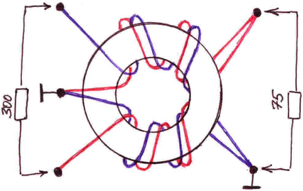
If the first 2 options worked at a frequency of no more than 270 MHz, then the next manufacturing method will allow you to enjoy a better picture, because the signal range can reach up to 490 MHz. The only detail that is unlikely to be found among the household trivia is the 300 to 75 ohm matching transformer. You will need to buy it in advance if you decide to make an antenna for your TV yourself as an experiment and improve your skills. Although there are instructions for making a homemade transformer, you can find and use it.

From the materials you will need:
- Scotch
- Cardboard
- Stationery knife
- Foil
- Stapler
- Scissors
- Marker
- Roulette
Having prepared this whole school set, let's get down to business!
First you need to sketch (or print on a computer) this diagram:


Now, according to the scheme, we cut out all the parts, including the necessary pieces of foil:


After that, you need to make a reflector measuring 35 * 32.5 cm (height and width). We glue one of the sides with foil.


In the middle we cut out two identical rectangles, which are necessary in order to completely assemble the homemade antenna signal trap for the TV. The rectangle should be 3.5 cm long, its purpose is to maintain the distance between the reflector and the auxiliary parts.


We glue the parts on a rectangle, and when the cardboard homemade product hardens, we drill holes for the TV cable.


We connect the transformer and insert the cable into the plug. More powerful TV antenna is ready to use! It should also be noted that this homemade option is suitable only for indoor use, because the paper quickly deteriorates on the street.
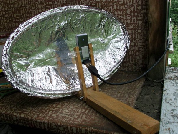
Another option for a powerful home-made device:
Idea number 4 - Apartment option
There is another way to make a powerful antenna for a TV from improvised means, which is suitable for both street and apartment use.
To manufacture the device, you will need the following materials and tools:
- 4-meter copper wire with a cross section of 4 mm square;
- board of any thickness, 55 cm long and 7 cm wide;
- wood screws;
- ruler or tape measure;
- simple pencil;
- screwdriver;
- soldering iron;
- plug.
So, first, according to the drawing, we drill holes in the board: 
Then we transfer the drawing data to the board and drill into the corresponding attachment points. 
Next, the copper wire must be cut into 8 pieces of 37.5 cm each. 
The insulation must be removed in the middle of each of the 37.5 cm lines (as shown in the picture). 
We cut off 2 more copper wire pieces 22 cm long and conditionally divide them into 3 equal parts, while at the points of inflection, again, we remove the insulation. 
We bend the prepared wire in bare places. We draw your attention to the fact that for those segments that are bent in half, the distance between the ends must be made 7.5 cm (the optimal value for receiving the signal of a homemade television antenna). 
Next, we attach the plug to the finished homemade product, and we already connect the TV cable to it. 
 This completes the manufacturing process. We choose a suitable place and install the device.
Here we have provided the most simple instructions. We hope that now you know how to make a home TV antenna with your own hands! We draw your attention to the fact that today on the Internet you can find many other options in which inventors do without cans and wires. Of the rest of the available tools, copper tubes, aluminum discs and electrodes are often used. The advantage of the options we have listed is that you can quickly make such TV antennas with your own hands, without spending the whole evening on it.
Related materials:
Visual video instructions for creating a simple antenna from cans
Assembling a digital antenna from a TV cable and a cardboard box
HDTV antenna from available tools
Like( 0 ) I do not like( 0 )
Despite the rapid development of the Internet, television remains the main source of information for the majority of the population. But in order for your TV to have a high-quality picture, you need a good antenna. It is not at all necessary to buy a TV antenna in a store, because you can make it yourself and save a lot of money at the same time.
How to make high-quality antennas for various broadcasting ranges and what materials to use at the same time, you can find out by reading our article.
There are many types and shapes of television antennas, below are the main ones:
- Antennas for receiving the "wave channel".
- Antennas receiving the "traveling wave".
- Loop antennas.
- Zigzag antennas.
- Log-periodic antennas.
- Array antennas.


 Array antennas
 Antennas for receiving digital television
The whole world, including our country, switched from analogue to digital broadcasting. Therefore, making an antenna with your own hands or buying it in a store, you need to know which antenna is best suited for receiving DVB-T2 format:

If you live not far from a TV tower, then you can easily make the simplest antenna for receiving a signal in DVB-T2 format with your own hands:
- Measure 15 centimeters of the antenna cable from the connector.
- Remove 13 centimeters of outer insulation and braid from the cut edge, leaving only the copper rod.
- Referring to the TV picture, align the rod in the desired direction.
All antenna is ready! It should be noted that such a primitive antenna is not capable of providing a high-quality and stable signal at a distance from the TV tower and in places with sources of interference.
Diy antennas
Let's look at several options for television antennas that you can make yourself from scrap materials:
Beer can antenna
An antenna from beer cans can be made in literally half an hour, using the funds at your fingertips. Of course, such an antenna will not provide a super-stable signal, but for temporary use in the country or in a rented apartment it will do quite well.  Beer can antenna
To make an antenna you will need:
- Two aluminum cans for beer or other drink.
- Five meters of television cable.
- Plug.
- Two screws.
- A wooden or plastic base on which the cans will be attached (many use a wooden hanger or mop).
- Knife, pliers, screwdriver, electrical tape.
After making sure that you have all of the above items in stock, do the following:
- Strip one end of the cable and attach the plug to it.
- Take the other end of the cable and strip 10 centimeters of insulation from it.
- Unbraid the braid and twist it into a cord.
- Peel off the plastic layer of the cable insulating shaft one centimeter.
- Take the cans and twist the screws in them in the center of the bottom or lid.
- Attach a rod to one can, and a cable sheathing cord to the other, screwing them onto the screws.
- Attach the cans to the base with electrical tape.
- Fasten the cable to the base.
- Insert the plug into the TV.
- As you move around the room, determine the place with the best signal reception and fix the antenna there.
There are other variations of this antenna, with four or even eight banks, but no obvious effect of the number of cans on the signal quality was found.
You can also learn how to make an antenna out of beer cans from the video:
Zigzag antenna Kharchenko
The antenna received its name in 1961, by the name of its inventor K.P. Kharchenko, who proposed using zigzag antennas for receiving television broadcasts. This antenna is very well suited for receiving digital signals.  Antenna Kharchenko
To make a zigzag antenna you will need:
- Copper wire with a diameter of 3-5 mm.
- TV cable 3-5 meters.
- Solder.
- Soldering iron.
- Plug.
- Insulating tape.
- A piece of plastic or plywood for the base.
- Fastening bolts.
First you need to make an antenna frame. To do this, take the wire and cut off a piece of 109 centimeters. Next, we bend the wire so that we get a frame of two parallel rhombuses, each side of the rhombus should be 13.5 centimeters, from the remaining centimeter make loops to fasten the wire. Using a soldering iron and solder, join the ends of the wire and close the frame.
Take the cable and strip the end so that you can solder the cable rod and shield to the frame. Next, solder the rod and cable shield in the center of the frame. Please note that the shield and the rod must not touch.
Place the frame on the base. The distance between the corners of the frame at the junction with the cable should be two centimeters. Make the base about 10 by 10 centimeters.
Strip the other end of the cable and install the plug.
If necessary, attach the antenna base to the rack for further roof installation.
You can see more detailed instructions for making Kharchenko's antenna in the video:
Coaxial antenna
To make the antenna, you will need a standard 75-ohm coaxial cable. To calculate the cable length required for the antenna, you need to find out the digital broadcasting frequency and divide it in megahertz by 7500, and round the resulting amount.  Cable antenna
After obtaining the cable length, do the following:
- Strip the cable on one side and plug into the antenna connector.
- Step two centimeters from the edge of the connector and make a mark from which you will measure the length of the antenna.
- After measuring the desired length, bite off the excess with pliers.
- In the area of the mark, remove the insulation and braiding of the cable, leave only the inner insulation.
- Fold the cleaned part at a 90-degree angle.
- Set up your TV with a new antenna.
You can visually consolidate the information by watching the video:
Satellite antenna
It should be noted right away that a tuner and a special set-top box are needed to receive a satellite signal. Therefore, if you do not have this equipment available, then creating a satellite dish with your own hands will not be possible, since you yourself can only make a parabolic reflector:

All of the above methods can be considered seriously only out of sports interest, since the manufacture of a parabolic reflector by hand is a very time-consuming and expensive process. In addition, it is very difficult to make accurate calculations of the parameters of a satellite dish at home. Therefore, we advise you not to be original and buy a complete set of satellite dishes.
Antenna amplifier
If in the place where you live there is a weak TV signal and an ordinary antenna cannot provide a high-quality picture on your TV, then an antenna amplifier can help in this situation. You can make it yourself if you know a little about electronics and know how to solder. 
Amplifiers should be installed as close to the antenna as possible. It is better to power the antenna amplifier through a coaxial cable through an isolation.  Decoupling power circuit
The decoupling is installed at the bottom of the TV and 12 volts is supplied to it from the adapter. Two-stage amplifiers consume no more than 50 milliamperes, for this reason the power of the power supply should not exceed 10 watts.
All connections of the antenna amplifier on the mast must be made using soldering, since the installation of mechanical connections will lead to their corrosion and rupture, during further operation in an aggressive environment.
There are times when you have to receive and amplify a weak signal in the presence of strong signals from other sources. In this case, both weak and strong signals enter the amplifier input. This leads to blocking the operation of the amplifier or transferring it to a non-linear mode, mixing both signals, which is expressed in the imposition of an image from one channel to the other. Reducing the supply voltage of the amplifier will help to correct the situation.
Note that decimeter amplifiers are highly influenced by signals in the meter range. To weaken the effect of meter signals, a high-pass filter is placed in front of the UHF amplifier, which blocks meter waves and passes signals only in the decimeter range.
Below is a diagram of a meter-range antenna amplifier:
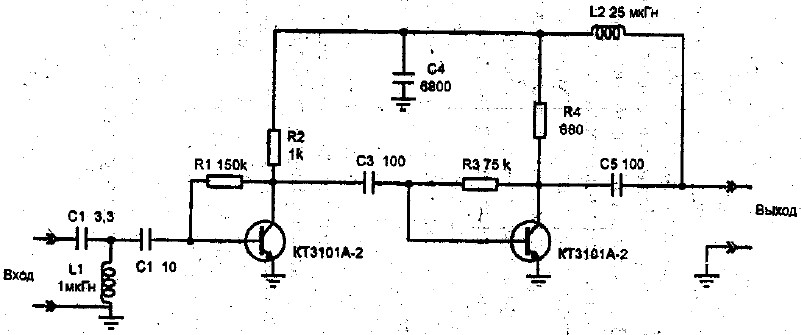
We also suggest that you familiarize yourself with the decimeter amplifier circuit:

You can get acquainted with the principle of operation of the antenna amplifier in the video:
Now, having familiarized yourself with the diagrams and armed with a soldering iron, you can safely start making the antenna amplifier.
We hope that our article on TV antennas was useful to you!
In the days of huge tube TVs, a good antenna for high-quality analog TV reception was in short supply. Those that could be bought in stores were not of high quality. Therefore, people made UHF television antennas with their own hands. Today, many are interested in homemade devices. And even when digital technologies are everywhere, this interest does not fade away.
Digital era
This era also touched on television. Today, T2 broadcasting is developing especially widely. It has its own characteristics. In those places where the signal level slightly exceeds the interference, a sufficiently high-quality reception is obtained. There is simply no further signal. The digital signal does not care about interference, however, in a situation of cable mismatch or various phase distortions, almost anywhere in the transmitting or receiving path, the picture can be squares even with a strong signal level.
Other changes have taken place in modern television. So, all broadcasting is carried out in the UHF range, the transmitters have good coverage. The conditions under which radio waves propagate through cities have changed dramatically.
Antenna parameters
Before you start manufacturing, you need to determine some of the parameters of these structures. They, of course, require in-depth knowledge in various areas of mathematics, as well as the laws of electrodynamics.
So, the gain is the ratio of the power at the input of the reference system to the power at the input of the antenna used. All this will work if each of the antennas creates the values of the intensity and flux density with the same parameters. The value of this coefficient is dimensionless.
Directional gain is the ratio of the field strength generated by the antenna to the field strength in any direction.

It must be remembered that parameters such as KU and KND are not interrelated. There is a UHF antenna for digital TV, which has a very high directivity. However, its gain is small. These constructions are directed into the distance. There are also highly directional designs. Here it comes in combination with a very powerful gain level.
Today you can not look for formulas, but use special programs. They have already taken into account all the necessary parameters. You just have to enter some conditions - and you will receive a complete calculation of the UHF antenna, in order to then assemble it.
Manufacturing nuances
Any structural element in which signal currents flow must be connected using a soldering iron or a welding machine. Such a knot, if it is in the open air, suffers from a breakdown in contact. From this, various antenna parameters and reception levels can become significantly worse.
This is especially true for points with zero potentials. According to experts, it is possible to observe the voltage in them, as well as the antinode of the current. More precisely, this is the maximum current value. Is it present at zero voltages? No wonder.
These areas are best made from solid metal. Creeping currents are unlikely to affect the picture if the connections are welded. However, due to their presence, the signal may be lost.
How and with what to solder?
The UHF antenna with your own hands is not very easy to make. This involves working with a soldering iron. Modern TV cable manufacturers no longer make it copper. Now there is an inexpensive alloy that is resistant to corrosion. These materials are difficult to solder. And if you heat them long enough, there is a risk of burning the cable.

Experts recommend using low-power soldering irons, low-melting solders, and fluxes. Do not spare the paste when soldering. The solder will lay down correctly only if it is under a layer of boiled flux.
Catch T2
In order to enjoy digital TV, it is enough to purchase a special tuner. But it doesn't have a built-in antenna. And those that are offered as special digital ones are too expensive and pointless.
Now we will learn how to catch T2 on a completely homemade construction. A homemade UHF antenna is simple, cheap, high quality. Try it yourself.
The simplest antenna
To assemble this structure, you will not even need to go to the store. To manufacture it, a conventional antenna cable is enough. You need 530 mm of wire for the ring and 175 mm from which the loop will be made.

The TV antenna itself is a ring of cable. The ends need to be stripped and then connected to the loop. And to the latter you need to solder a cable that connects to the T2 tuner. So, on the ring, the screen and the central core are connected to the loop screens. In the latter, the central veins are also connected. And the cable to the tuner is soldered as standard to the screen and the central core.
So the UHF antenna turned out, made by hand. Its design turned out to be very cheap and practical. And it works no worse than expensive store options. It needs to be fixed on plywood or plexiglass. Construction clamps are perfect for this.
"People's" antenna
This design is an aluminum disc. The outer diameter of the element should be 365 mm and the inner diameter 170 mm. The disc should be 1 mm thick. First you need to make a cut in the disc (10 mm wide). In the place where the cut is made, a PCB made of PCB should be installed. It should be 1 mm thick.

The board must have holes for the MZ screws. The board must be glued to the disk. Then you need to solder the cable leads to it. The center core should be soldered to one side of the disc, the shield to the other. In terms of quality, such a TV antenna will receive better with two discs, especially if it is located far from the TV repeater.
Universal antenna
Nothing supernatural will be used to make this structure. We will make it from various materials at hand. However, although it is homemade, it will work perfectly in the entire decimeter range. So, this UHF antenna, quickly made with its own hands, is in no way inferior to store-bought, more expensive designs. To receive T2, it will be enough completely.

So, to assemble this structure, you need empty cans of canned food or beer. You need 2 cans with a diameter of 7.5 cm. The length of each is 9.5 cm. You also need to stock up on strips of textolite or getinax, always with foil.
Our cans need to be connected to the PCB strips using a soldering iron. The plate of this material, which will connect the containers at the top, must be covered with a continuous copper foil. On the bottom plate, the foil should be cut. This is done for convenient cable connection.
It is necessary to assemble the structure in such a way that the total length is not less than 25 cm. This antenna (UHF range) is a broadband balanced dipole. Due to its surface area, it has high amplification factors.
If suddenly you cannot find suitable cans, then you can use containers with a smaller diameter. However, then the foil will have to be cut at the top connecting plate as well.
"Beer" antenna
Do you like to drink beer? Don't throw away the cans. You can make a good antenna out of them. To do this, you need to fix two beer cans on any dielectric material.
First you need to choose the right cable, and then bring it to mind. For this, the cable must be stripped. You will see a shielding foil. There will be a protective layer underneath. But under it you can directly observe the cable.
For our antenna, we need to strip the top layer of this wire about 10 cm. The foil needs to be carefully twisted so that we end up with a branch. The protective layer for the central core must be stripped by 1 cm.
On the other hand, you need to solder the TV plug to the cable. If you were a subscriber of cable networks, then this part and cable will not even have to be purchased separately.
Now for the cans. It is advisable to use beer containers with a volume of 1 liter. However, good German beer in such cans is expensive, and domestic beer is not sold.

Banks need to be uncorked very carefully. Then you need to free the container from the contents, and then dry it well. Next, using a self-tapping screw, connect our screen on the cable and the jar. The central core must be screwed to the second.
For a better image quality, it is better to connect the containers and the cable with a spike.
It is necessary to fix the cans on some kind of dielectric material. It should be noted that they should be located on one straight line. The distance between them depends on the capacity. All this is selected only empirically.
Zigzag
The UHF zigzag antenna has the most simple design. The part itself is broadband. Its device allows for various deviations from the initial design parameters. In this case, its electrical parameters are almost not violated.
Its input impedance in a certain range depends on the size of the conductors that will form the basis of the canvas. There is a dependence here. The greater the width or thickness of the conductors, the better the antenna will be matched to the feeder. In general, any conductors can be used to make the web. Plates, tubes, corners, and much more are suitable for this.

In order to increase the directivity of such an antenna, it is permissible to use a flat screen, which will act as a reflector. The latter will reflect high-frequency energy towards the antenna. Such screens are often of serious size, and the phase depends mainly on the distance.
From a practical point of view, a reflector is rarely made of a solid sheet of metal. More often it is made in the form of conductors that are connected in one plane. For design reasons, you should not make a screen that is too dense. The conductors from which the screen itself will be made are connected by welding or soldering to a metal frame.

This design is made very simply. It works well in the UHF range. In the USSR, it was a real people's irreplaceable model. It has a small size, so it can be used as an indoor UHF antenna.
The material will be copper tubes or aluminum sheet. The side pieces can be solid metal. Often they are covered with a net or covered with a tin. If one of the indicated methods is used, in this case, the structure must be soldered along the contour.
Do not bend the cable sharply. How to carry out this element, you can see in the pictures presented.
It must be guided in such a way that it reaches the side corner, but does not go beyond the antenna or side square.
Indoor antenna MV DMV
This design is designed for easy and reliable reception of digital TV signals. It can be made easily and very quickly. To do this, you need an aluminum or copper bar. Its length should be up to 1800 mm. This antenna can also be used as an outdoor antenna.

The design is a rhombus-shaped frame. There should be two of them. One acts as a vibrator, the other acts as a reflector. To receive T2, it is necessary that the side of our rhombus is approximately 140 mm, and the distance between them is 100 mm.

After the frame is made and the structure gains rigidity, a dielectric is mounted between the two ends of our rod. It could be anything. The shape and size are completely unimportant. The distance between two points of the bars should be approximately 20 mm. The tops of our rhombuses need to be connected.

The feeder can be made from a cable. It must be connected to brass or copper petals, which should already be attached to the antenna lead.
If the resulting design does not meet your expectations, for example, poor reception quality or the repeater is far away, you can equip the antenna with an amplifier, and you will end up with an active UHF antenna. It is used both in the city and in the country.
The simplest UHF loop antenna
This construction resembles the number "zero". By the way, this is the coefficient of its amplification. It is ideal for T2 reception. This part is capable of performing better than the products offered in stores.
It is also called digital, because with it you can perfectly catch digital broadcasting. It is narrowband, which is a significant advantage. It works on the principle of a selective valve, which makes it possible to talk about reliable protection against interference.

For assembly, you will need an ordinary 75 ohm coaxial cable, as well as a regular TV plug. It is better to choose a cable with a large diameter from all options. You can use a cardboard box or something else as a stand.
How long the frame will be, we determine using programs for calculating antenna parameters. The material for making the frame can be used the same as for the cable. By the way, for calculations, you need to know the frequencies of digital broadcasting in your city.

The central core of the cable is not needed in the frame structure. The stripped wire is twisted together with the core and braid of the frame. Then this connection must be soldered.
The structure must be placed on a dielectric base. Better to keep it away from your tuner. It is important that there is no voltage at the antenna input.
So, we figured out how the UHF antenna is made with our own hands. As you can see, this is not a very difficult task. But now you can watch your favorite TV shows in digital quality. And such a structure is installed in the same way as an ordinary store one - on the roof. Screws or bolted connections can be used. It should be installed in a safe place so that during gusts of wind it does not fly off along with a piece of slate. It is desirable that the antenna be mounted at the highest possible height. In this way, you will eliminate the appearance of interference during the broadcasting of cable or digital television.

The era of digital signals has arrived. All broadcasting TV companies began to work in a new format. Analog TVs are living out their days. They are still in working order and are available in almost every family.
In order for the old models to successfully finalize their resource, and people can use them when watching digital broadcasting, it is enough to connect the DVB-T set-top box to the TV receiver and catch the TV wave signals with a special antenna.
Any home craftsman is able not to buy an antenna in a store, but to make it with his own hands from available tools for watching digital TV programs at home or in the country. The two most affordable constructs are described in this article.
A bit of theory
Principle of operation of an antenna for digital packet television
Any television signal propagates in space from the emitters of the transmitting television tower to the television antenna by a sinusoidal electromagnetic wave with a high frequency measured in megahertz.

When an electromagnetic wave passes through the surface of the receiving antenna beams, a voltage V is induced in it. Each half-wave of a sinusoid forms a potential difference with its own sign.
Under the influence of the induced voltage applied to the closed receiving circuit of the input signal with resistance R, an electric current flows in the latter. It is amplified and processed by the digital TV circuitry and output to the screen and speakers as picture and sound.

For analog models of TV receivers, an intermediate link works between the antenna and the TV - the DVB-T set-top box, which decodes the digital information of the electromagnetic wave into its usual form.
Vertical and horizontal polarization of digital TV signal
In television broadcasting by state standards, it is customary to emit electromagnetic waves in only two planes:
- horizontally.

In this way, the transmitters direct the emitting signals.
And users just need to rotate the receiving antenna in the desired plane to maximize the removal of the power potential.
Digital Packet TV Antenna Requirements
TV transmitters spread their signal-waves over short distances, limited by the line-of-sight from the top point of the TV tower emitter. Their range rarely exceeds 60 km.
For such distances, it is sufficient to provide a small power of the emitted TV signal. But, the intensity of the electromagnetic wave at the end of the coverage area should form a normal voltage level at the receiving end.
A small potential difference is induced at the antenna, measured in fractions of a volt. It creates currents with small amplitudes. This imposes high technical requirements on the assembly and workmanship of all parts of digital reception devices.
Antenna design should be:
- made accurately, with a good degree of accuracy, excluding the loss of electrical power of the signal;
- directed strictly along the axis of the electromagnetic wave coming from the transmitting center;
- oriented by the type of polarization;
- protected from extraneous interference signals of the same frequency coming from any sources: generators, radio transmitters, electric motors and other similar devices.
How to find out the initial data for calculating the antenna
The main parameter influencing the quality of the received digital signal, as can be seen from the explanatory first figure, is the length of the electromagnetic radiation wave. Symmetrical arms of vibrators of various shapes are created under it, the overall dimensions of the antenna are determined.
The wavelength λ in centimeters can be easily calculated using a simplified formula: λ = 300 / F. It is enough just to find the frequency of the received signal F in megahertz.
We will use the search for GUGL for this and ask him for a list of regional TV communication points for our area.
As an example, a fragment of the data table for the Vitebsk region is shown with a red rectangle highlighting the transmitting center in Ushachi.

Its wave frequency is 626 megahertz, and the type of polarization is horizontal. This data is quite enough.
We carry out the calculation: 300/626 = 0.48 m. This is the length of the electromagnetic wave for the antenna being created.
We divide it in half and we get 24 cm - the required half-wave length.
The maximum value of the tension reaches in the middle of this area - 12 cm. It is also called the amplitude. A whip antenna is made for this size. It is usually expressed by the formula λ / 4, where λ is the length of the electromagnetic wave.
The simplest TV antenna for digital television
It requires a piece of coaxial cable with a characteristic impedance of 75 ohms and an antenna plug. I managed to find a ready-made two-meter piece in the old stock.

From the free end, I cut off the outer shell with an ordinary knife. I take the length with a small margin: when setting up it is always easier to bite off a small piece.

Then I remove the shielding layer from this section of the cable.


The work is done. It remains to insert the plug into the connector on the TV signal set-top box and direct the bare wire of the inner core across the incoming electromagnetic wave, taking into account the horizontal polarization.

The antenna should be placed directly on the windowsill or fixed to the glass, for example, with a piece of tape or tied to the blinds mount. Reflected signals and interference can be shielded with a strip of foil located at a short distance from the central core.
Such a design is done literally in a dozen minutes and does not require special material costs. It's worth trying it. But, it is capable of working in the area of reliable signal reception. My building is shielded by a mountain and a multi-storey building. The transmitting TV tower is located at a distance of 25 km. Under these conditions, the digital electromagnetic wave is reflected many times and poorly received. I had to look for another technical solution.
And for you on the topic of this design, I propose to watch the video of the owner Edokoff "How to make an antenna for digital TV"
Antenna Kharchenko at 626 MHz
To receive analogue TV broadcasting signals of various wave frequency ranges, the design of a zigzag broadband antenna used to work well for me, which does not require complex manufacturing.
I immediately remembered one of their effective varieties - the Kharchenko antenna. I decided to use its design for digital reception. I made the vibrators from a flat copper bus, but it is quite possible to get by with a round wire. This will make it easier to bend and align the ends.

How to determine the dimensions of a specific antenna
Online calculator
Let's use the omniscient Google search. We write in the command line: "Calculation of the Kharchenko antenna" and press Enter.

We choose any site you like and perform an online calculation. I went to the first one that opened. Here's what he calculated for me.

I presented all his data with a picture with the designation of the name of the dimensions of the Kharchenko antenna.

Manufacturing of antenna structure parts
I took the information provided as a basis, but did not exactly maintain all the dimensions. I know from previous practice that the antenna works well in the broadband wavelength range. Therefore, the dimensions of the parts were just slightly overestimated. The half-wave of each harmonic of the sinusoid of the electromagnetic TV signal will fit into the shoulder of each vibrator and will be received by it.
Based on the selected data, I made blanks for the antenna.

Vibrator design features
The connection of the ends of the shank for the figure-eight is created in the center during the bending stage. I soldered them with a soldering iron.

I have it created according to the "Moment" principle, made by hand from old transformers, it has been working for two decades. They even soldered a copper wire 2.5 squares in a thirty-degree frost. Works with transistors and microcircuits without burning them out.
I plan to describe its design in a separate article on the site in the near future for those who also wish to make it with their own hands. Follow the publications, subscribe to notifications.
Connecting the antenna cable to the vibrator
The copper core and braid were simply soldered to the metal of the figure eight from different sides along its center.

The cable was tied to a copper bus, bending it in a loop in the shape of a semi-square vibrator. In this way, the cable and antenna impedances are matched.
Shielding grid design
In fact, Kharchenko's antenna often works fine without shielding the signals, but I decided to show its manufacture. I took a wooden block for the base. I did not paint and saturate with varnish: the structure will be used indoors.
In the back of the block I drilled holes for attaching the screen wires and inserted them, and then jammed them.

The result is a screen for Kharchenko's antenna. In principle, it can be made of a different design: cut out of a piece of frontal armor of a tank or cut out of food foil - it will work in about the same way.

On the reverse side of the bar, I fixed the structure of the vibrator with a cable.

The antenna is ready. It remains to install it on a window to work in vertical polarization.

When a television receiver is located at a great distance from the transmitting generator, its signal strength gradually weakens. It can be increased by special electronic devices - amplifiers.
You just need to clearly see the difference between the signals received by the antenna, which can be:
- just weakened;
- contain high-frequency interference that distorts the shape of a digital sinusoid to the shape of some kind of "karyabola".
In both cases, the amplifier will do its part and raise the power. Moreover, the TV will clearly perceive and display the weakened signal, and with the reinforced "karyabola" there will be playback problems.
To eliminate such interference waves are designed:
- h / h filters;
- screens.
They need to be measured with an oscilloscope, and the ways of using different designs should be analyzed on a case-by-case basis. The antenna is not to blame here.
- do not use purchased when your grandfather went to first grade;
- don't buy the cheapest one with virtually no braid. Choose normal ones;
- do not shorten as much as possible;
- do not make sharp creases;
- do not twist the excess into a bay.
Even if you connect the pieces with a standard coaxial connector, the signal quality is guaranteed to deteriorate.
Using the amplifier
This inexpensive summer cottage antenna gives a good result. If you plan to receive this antenna only, then two of its long side "mustaches" can be unscrewed.
Wave channel
They give good results, especially for remote signal reception when it is weak enough.
Polish
Many TV viewers use a "Polish" antenna - a grid and four rows of antennae. It doesn't matter where it was made, they used to call it "Polish", and sometimes "mesh". Very often, it demonstrates not the best characteristics for receiving a digital signal.
Very few are represented in the trading network, they are familiar only to radio amateurs. They are poorly protected from radio interference, although they have a fairly uniform frequency response.
Room
Only in very rare cases does it show good results for. Even if you paid dearly for it, the result may be zero.
If you want only a room antenna as a terrestrial antenna for a summer residence, you may be "advised" to buy it at a higher price and "better". But if you hope that she will start giving you a wonderful signal in your room, then this hope is in vain. If the signal in the house is bad, no antenna will help. External is the solution to the problem if there is no reception in the room.
Satellite
Remember? We're talking ethereal, so forget satellites. You will not receive terrestrial television in the DVB-T2 standard through a satellite tuner. You will not be connecting a T2 tuner to. We receive the T2 signal from the nearest broadcasting tower in the decimeter range. On an ordinary terrestrial antenna for a summer residence, not a "plate".