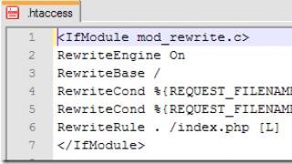
What are CASE-tools CASE-tools (from English Computer-Aided Software
Engineering) are tools
IC design automation.
CASE-TOOLS are software engineering techniques for
designing software, which
allow to provide high quality programs,
error-free and easy to maintain
software products.
CASE is also understood as a set of funds
information systems design with
using CASE tools.
Case funds
Case means include any software thatautomates different stages Life cycle
Software and has the following characteristics:
1. There is a powerful graphical tool for
description of the IP, which provides usability
user,
2. There is integration individual components
Case- means,
3. Centralized storage is used
Design Data Repository.
Design functions that are most often automated within the framework of CASE tools:
-analysis and formulation of IP requirements;
database and application design;
generation program code;
testing;
software quality assurance;
IC configuration management;
project management, etc.
The result of using CASE-tools:
optimization of the IS structure;reduction in development costs;
increasing the efficiency of IP;
reducing the likelihood of errors when
designing IP.
Typical Case Tool Architecture
Repository
The core of any software design system is the repository.The repository is a specialized database,
which is used to display the state of the system at any time
time and contains information about all objects of the project IP:
The names of the designers and their access rights,
Organized structures,
Components of charts and charts in general,
Data structures,
Relationships between charts,
Program modules, procedures and module libraries.
Classification of Modern Case Tools:
1. Classification of Case funds bysupported methodologies:
-
functional or structure-oriented;
-
object oriented;
-
complex-oriented.
2. Classification of Modern Case funds by types:
Reflects the functional orientation of funds forprocesses life cycle software development
providing:
analysis tools - designed to build and
analysis of the domain model;
database design tools;
application development tools;
Process reengineering tools;
planning and project management tools;
testing tools;
documentation tools.
Examples of case tools of various types:
Analysis tools (Design, BpWin);Analysis and design tools (Designer - Oracle);
Database design tools (ErWin, Designer - Oracle);
Application development tools (Developer - Oracle,
Delphi);
Reengineering tools (ErWin, Rational Rose).
3. Classification of Modern Case funds into categories:
Defines the functions performed by tools and includes:separate local funds decisive small autonomous
tasks, a set of partially integrated tools covering
most stages of the life cycle and fully integrated
means covering the entire life cycle of information
systems and linked by a common repository.
Typical CASE tools are:
configuration management tools;
data modeling tools;
analysis and design tools;
model transformation tools;
code editing tools;
code generators;
tools for building UML diagrams.
Other types of classification of Case-funds:
4.Case-funds classification by support
graphic notations;
5.
Classification of Case-funds by degree
the integration of individual instruments;
6.
Classification of Case-tools by type and architecture
used computer technology;
7.
Classification of Case-funds by the type of collective
development;
8.
Classification of Case-funds by the type of used
operating environment.
When choosing Case funds, the following aspects should be considered:
The presence of a database, archive or dictionary;Availability of interfaces with other Case systems;
Information export and import capabilities;
Open architecture;
Availability of required methodologies;
Availability of graphic tools to support the project;
Possibility of automatic generation of program code;
Ability to plan and manage a project.
Case Tool Universal Modeling Language UML
The UML was created with the following goals:provide developers with a unified visual language
modeling;
provide mechanisms for the expansion and specialization of the language;
ensure language independence from programming languages, and
development processes.
Relationship of UML Diagrams
Variant diagramuse of
Diagram
sequences
Diagram
classes
Diagram
cooperation
Diagram
components
Diagram
states
Diagram
deployment
Diagram
activities
IBM Rational Rose Case Tool
Rational Rose is a modern and powerful analysis tool,modeling and development of software systems,
covering the entire software life cycle
from business process analysis to code generation on
a given programming language.
Such an arsenal allows not only to design a new
information system, but also to modify the old one,
by performing a reverse engineering process.
Key features of the Rational Rose package:
forward and reverse engineering in languages: ADA,Java, С, C ++, Basic;
support for COM, DDL, XML technologies;
the ability to generate database schemas Oracle and SQL.
Rational Rose product versions:
Rational Rose Modeler allows you to analyze business processes anddesign the system. But does not support code generation.
Rational Rose Professional version Depending on the selected programming language
allows for forward and reverse engineering. Can only be ordered in
specific configuration (e.g. Rose Professional C ++ or Rose Professional C ++
DataModeler). Doesn't generate 100% executable code. As a result, the developer receives
framework code of the information system in a specific (ordered) language
programming, which later still needs to be finalized.
Rational Rose RealTime is specifically designed to provide 100% executable
code in real time, allows for forward and backward
design in C or C ++ languages. At the output, the model is automatically compiled
and is compiled into an executable file.
Rational Rose Enterprise version this version of the product covers the entire range of tasks for
design, analysis and code generation. All functions of others are supported
editions, except for the possibility of 100% code generation.
The Rational Rose DataModeler version of the database design product.
DataModeler functionality is included with Rose Enterprise or Professional.
Into MS package Visual studio 6.0 embedded Visual Modeler is a stripped-down version of Rational Rose 98.
More information on the Rational Rose package:
The free version of Rational Rose does notexists;
for educational institutions all software
IBM software is available free of charge;
free use in educational purposes maybe
as part of the IBM Academic Initiative.
Hierarchical CASE-models correspond much better to the large dimension of the problem. CASE (Computer-Aided Software / System Engineering) stands for computer-aided software or system design.
CASE-technology is an actual and intensively developing direction of CAD development in the field of software products and information processing systems. Almost no major foreign software product is currently being created without the use of CASE-tools.
Among the domestic systems created using CASE-tools, the BOSS-CORPORATION system of IT Co. should be noted. At all stages of the creation of this system, development tools related to the Oracle 2000 family (Designer / 2000, Developer / 200, Programmer / 2000) were used.
The area of application of CASE-technologies refers to the creation, first of all, of economic information systems, which is explained by the mass character of these systems.
It should be noted that CASE-technologies are used not only to create automated control systems, but also to develop models of systems that help in making decisions in the field of strategic planning, company financial management, personnel training, etc. This area of application of CASE technologies has received its own name - business analysis.
CASE-technologies are also used where the problematic of the subject area is very complex, for example, in the development of system software.
Let's consider the methodological foundations of CASE technologies.
The basis of the CASE methodology is modeling. CASE-technology is a model method of system design automation.
CASE technology is based on the paradigm: methodology - method - notation - means
The methodology defines general approaches to the assessment and selection of a system option, the sequence of stages and design stages, and approaches to the selection of methods.
The method specifies the order of design of individual components of the system (for example, methods for designing data flows in the system, setting specifications (descriptions) of processes, representing data structures in the storage, etc. are known).
Notations are graphical notations and rules used to describe the structure of a system, stages of information processing, data structure, and so on. Notations include graphs, diagrams, tables, flowcharts, formal and natural languages.
Finally, the tools are toolkits, design automation tools in the form of software products for providing an interactive design mode (creating and editing a graphical project of an information system) and code generation of programs (automatically generating system program codes).
The design methodology based on computer support, obviously, requires the construction of a formalized description of the information system in the form of an information model. The construction of a CASE-model of the system provides for the decomposition of the system and the hierarchical ordering of the decomposed subsystems.
The system model should reflect:
The functional part of the system;
Relationships between data;
System state transitions when working in real time. To model the information system in the three indicated aspects, three types of graphic tools with certain notations are used.
1. Diagrams of data flows - DFD (Data Flow Diagrams). They are used in conjunction with data dictionaries and process specifications.
2. Diagrams "entity-relationship" - ERD (Entity Relationship Diagrams), showing the relationship between data.
3. State Transitign Diagrams - STD (State Transitign Diagrams) to reflect the time-dependent behavior of the system (in real time).
DFD plays a leading role in modeling.
DFD is designed to reflect the relationship between sources and receivers of data (so-called external entities in relation to the information system), data streams, processing processes (computational processes corresponding to the functions of the system), data storages (storage).
The graphical presentation of the data flow diagram on the display screen provides visualization of the simulation and the convenience of correcting the main components of the model online.
Since graphical representation is not enough to accurately define DFD components, textual descriptions and other means of concretizing processing processes and data structures are used.
Thus, data streams are concretized in terms of their structure in data dictionaries. Each process (system function) can be detailed using a lower-level DFD, where it is split into several processes with the simultaneous granularity of data streams.
Process detailing ends when the description of each detailed process can be done using the chosen process algorithm writing method. The process specification contains the process number and name, lists of input and output data names from the data dictionary, and a process algorithm that transforms the input data streams into input ones. The CASE technology uses such methods of setting process algorithms as:
Text description;
Natural structured language;
Decision tables;
Decision trees;
Visual languages;
Programming languages.
Programming languages (C, Cobol, etc.) cause difficulties in writing algorithms in relation to DFD, since they require the use of data dictionaries, in addition to data streams, and require synchronous correction of process specifications when correcting DFD.
A structured natural language is easily understood not only by designers and programmers, but also by end users. This is his dignity. However, it does not provide automatic code generation due to the presence of ambiguities.
Tables and decision trees, clearly reflecting the relationship of a combination of conditions with the necessary actions, do not have procedural capabilities for code generation of programs.
Visual languages provide automatic code generation, but the process specifications presented with their help are difficult to correct.
The content of each data warehouse represented in a data flow diagram is described by a data dictionary and ERD data model. In the case of real-time system operation, DFD is supplemented by STD.
The hierarchical structure of the CASE model is shown in Fig. 11.9.
An important methodological principle of the CASE technology for creating an information system is a clear division of the process of creating a system into 4 stages:
Pre-design (stage of analysis, prototyping, and building a model of the system requirements);
Design, assuming logical design of the system (without programming);
Programming stage (including designing a physical database);
Post-project, including commissioning, operation and maintenance of the system.
At the pre-design stage, a model of requirements for the system is built, that is, a detailed description of what it should do, without specifying ways to implement the requirements.
At the design stage, the requirements model is refined (the development of a detailed hierarchical model based on DFD and process specifications) and its extension to the implementation model at the logical level. At the end of this stage, the project is closely monitored at the level of the logical implementation model.
The next stage (programming) is the physical design of the system. This stage provides for automatic code generation according to the specifications of the system software processes and the physical design of the database.
The final post-design stage begins with acceptance tests. This is followed by the commissioning, maintenance and development of the system.
The sequence of operations for creating an information system based on CASE technology is shown in Fig. 11.10.
Let's consider the factors of CASE-technology efficiency.
1. It should be noted that the CASE-technology creates an opportunity and provides for the transfer of the center of gravity in the complexity of creating a system at the pre-design and design stages. Careful elaboration of these stages interactively with computer support reduces the number of possible mistakes in design, which are difficult to correct at subsequent stages.
2. The graphical form of the model presentation, which is understandable for non-programmers, makes it possible to implement the principle of user design, which provides for the participation of users in the creation of the system. The CASE model allows you to achieve mutual understanding between all participants in the creation of the system (customers, users, designers, programmers).
3. The presence of a formalized model of the system at the pre-design stage creates an opportunity for multivariate analysis with prototyping and an approximate assessment of the effectiveness of options. Analysis of the prototype system allows you to adjust the future system before it is physically implemented. This approach speeds up and reduces the cost of creating a system.
4. Consolidation of the system requirements in a formalized form relieves designers from the need for numerous adjustments for new user requirements.
5. The separation of system design from programming creates the stability of design solutions for implementation on different software and hardware platforms.
6. The presence of a formalized model for the implementation of the system and the appropriate automation tools allows for automatic code generation of the system software and create a rational database structure.
7. At the stage of system operation, it becomes possible to make changes at the model level without referring to the program texts, possibly by the efforts of the company's automation department specialists.
8. The system model can be used not only as a basis for its creation, but also for the purpose of automated training of personnel using diagrams.
9. Based on the model of the operating system, business analysis can be performed to support management decisions and business reengineering when changing the direction of the firm.
Consider the software that provides the CASE-technology. Depending on their functional purpose, they are subdivided into the following classification groups, which provide:
Analysis and design of an information system;
Database design;
Programming;
Maintenance and reengineering;
Management of the design process.
Analysis and design tools are used to build a CASE-model of both the current and the implemented control system. They support the graphical construction and control of a hierarchical model of data flow diagrams and the description of its components. These tools allow analysts and designers to access the designed system database (repository).
These funds include: domestic CASE package. Analyst, Design / IDEF (Meta Software), The Developer (ASYST Technologies), etc.
To accommodate user requirements, prototypes of user interfaces are created, including menus, displays and reports in the form of tables or graphs. An example of a software tool for creating a user interface is Developer / 2000 (Oracle).
Database design tools provide logical data modeling, automatic conversion of data models to third normal form, and generation of database schemas. Examples of such tools are Designer / 2000 by Oracle, ERWin (Logic Works), etc.
The programming tools support automatic code generation from process specifications, testing and documenting the program. These include Programmer / 2000 (Oracle), DECASE (DEC), APS (Sage Software), etc.
Maintenance and reengineering tools allow you to make changes to the system at the model level under changing business conditions (Adpac CASE Tools from Adpac, etc.).
Design process management tools support the planning and control of the implementation of a complex of design work, as well as the interaction of analysts, designers and programmers based on a common project database (for example, the Project Workbench of Applied Business Technology). The urgency of creating an integrated package of CASE-technology support tools at all stages of the information system life cycle is obvious.
Federal Agency for Education
Federal state educational institution Higher professional education "Chuvash State University named after IN Ulyanova "
Financial and Economic Institute
Faculty of Economics
Abstract on the topic: CASE-technologies for designing automated information systems
Completed by a student
EK 22-06 groups
Evgrafova I.A.
Checked by: Pavlova S.Yu.
Cheboksary 2007
· Introduction ………………………………………………………… ..3
· Life cycle of information system software …………………………………………………………… .5
· RAD technologies for prototyping applications ………… ... 7
· Structural method of software development …… 10
· Used literature ……………………………………… ..17
Introduction
Over the past decade, a new direction in software engineering has been formed - CASE (Computer-Aided Software / System Engineering) - literally translated - the development of software for information systems with the support (with the help) of a computer. Currently, there is no generally accepted definition of CASE; the term CASE is used in a very broad sense. The original meaning of the term CASE, limited to issues of automation of the development of only software, has now acquired a new meaning, covering the process of developing complex automated information systems as a whole. Now, the term CASE tools means software tools that support the processes of creating and maintaining IS, including the analysis and formulation of requirements, design of application software (applications) and databases, code generation, testing, documentation, quality assurance, configuration management and project management, and also other processes. CASE tools together with system software and hardware form a complete AIS development environment.
CASE tools allow you not only to create the "right" products, but also to provide the "right" process for their creation. The main goal of CASE is to separate software design from its coding and subsequent development stages, as well as to hide all details of the development environment and software functioning from the developers. When using CASE technologies, all stages of the software life cycle (more on this will be discussed below) of the information system change, while the greatest changes relate to the stages of analysis and design. Most of the existing CASE tools are based on structural (mainly) or object-oriented analysis and design methodologies that use specifications in the form of diagrams or texts to describe external requirements, relationships between system models, dynamics of system behavior, and software architecture. Such methodologies provide a rigorous and visual description of the designed system, which begins with its general overview and then is detailed, acquiring a hierarchical structure with all a large number levels. CASE technologies are successfully used to build almost all types of software systems, however, they occupy a stable position in the following areas:
♦ ensuring the development of business and commercial software, the widespread use of CASE-technologies are due to the massiveness of this applied field, in which CASE is used not only for software development, but also for creating systems models that help solve the problems of strategic planning, financial management, determining the policy of firms, training personnel, etc. (this area received its own name - business analysis);
♦ development of system and control software. The active use of CASE-technologies is associated with the great complexity of this issue and with the desire to increase the efficiency of work.
CASE is not a revolution in software engineering, but the result of the natural evolutionary development of the entire industry of tools previously called instrumental or technological. From the beginning, CASE technologies have evolved to overcome the limitations of structural design methodologies in the 1960s and 1970s. XX century (complexity of understanding, high labor intensity and cost of use, difficulties in making changes to design specifications, etc.) due to their automation and the integration of supporting tools. Thus, CASE technologies cannot be considered independent methodologies; they only develop structural methodologies and make their application more efficient through automation.
In addition to automating structural methodologies and, as a consequence, the possibility of using modern methods of system and software engineering, CASE tools have the following main advantages:
♦ improve the quality of the software being created by means of automatic control (first of all, project control);
♦ allow for a short time to create a prototype of a future system, which allows you to assess the expected result at an early stage;
♦ speed up the design and development process;
♦ free the developer from routine work, allowing him to concentrate entirely on the creative part of the development;
♦ support the development and maintenance of development;
♦ Support development component reuse technologies.
The emergence of CASE-technology and CASE-tools was preceded by research in the field of programming methodology. Programming has acquired the features of a systems approach with the development and implementation of high-level languages, methods of structural and modular programming, design languages and means of their support, formal and informal description languages system requirements and specifications, etc. In the 70-80s. a structural methodology began to be applied in practice, providing developers with strict formalized methods for describing AIS and the accepted technical solutions... It is based on a visual graphic technique: schemes and diagrams are used to describe various types of AIS models. The clarity and rigor of the structural analysis tools allowed the developers and future users of the system from the very beginning to informally participate in its creation, discuss and consolidate the understanding of the main technical solutions. However, the widespread use of this methodology and adherence to its recommendations in the development of contact AIS was quite rare, since with manual (manual) development it is almost impossible. This contributed to the emergence of a special class of software and hardware tools - CASE-tools that implement the CASE-technology for creating and maintaining AIS.
It should be understood that the successful use of CASE tools is impossible without understanding the underlying technology on which these tools are based. By themselves, CASE software tools are tools for automating the design processes and maintenance of information systems. It is impossible to use CASE-tools without understanding the methodology of designing IS.
1. Life cycle of information system software
One of the basic concepts of the AIS design methodology is the concept of the life cycle of its software (LC software). The life cycle of software is an ongoing process that begins from the moment a decision is made on the need to create it and ends at the moment of its complete withdrawal from service.
The structure of software lifecycle is based on three groups of processes:
♦ main processes of software lifecycle (purchase, delivery, development, operation, maintenance);
♦ supporting processes that ensure the execution of the main processes (documentation, configuration management, quality assurance, verification, validation, assessment, audit, problem solving);
♦ organizational processes (project management, creation of project infrastructure, definition, assessment and improvement of the life cycle itself, training).
Development includes all work on the creation of software and its components in accordance with the specified requirements, including the preparation of design and operational documentation, preparation of materials necessary to check the operability and appropriate quality of software products, materials necessary for organizing personnel training, etc. Software development usually includes analysis, design and implementation (programming).
Operation includes work on the implementation of software components into operation, including configuring the database and user workstations, providing operational documentation, training personnel, etc. and direct operation, including localizing problems and eliminating the causes of their occurrence, modification of software within the established regulations, preparation of proposals for improvement, development and modernization of the system.
Project management is related to the planning and organization of work, the creation of teams of developers and control over the timing and quality of work performed.
The technical and organizational support of the project includes the choice of methods and tools for the implementation of the project, the definition of methods for describing the intermediate states of development, the development of methods and tools for software testing, personnel training, etc. Project quality assurance is associated with the problems of software verification, verification and testing. Verification is the process of determining whether the current state of development achieved at a given stage meets the requirements of that stage. Verification allows you to assess the compliance of development parameters with the original requirements. Verification overlaps with testing, which is concerned with identifying the differences between actual and expected results and assessing the conformity of the software characteristics to the original requirements. In the process of project implementation, an important place is occupied by issues of identification, description and control of the configuration of individual components and the entire system as a whole.
Configuration management is one of the auxiliary processes that support the main processes of the software life cycle, primarily the processes of software development and maintenance. When creating projects of complex IS, consisting of many components, each of which may have varieties or versions, the problem arises of taking into account their connections and functions, creating a unified structure and ensuring the development of the entire system. Configuration management allows you to organize, systematically take into account and control software changes at all stages of the life cycle. General principles and recommendations for configuration accounting, planning and software configuration management are reflected in the draft ISO 12207-2 standard.
Each process is characterized by certain tasks and methods of their solution, initial data obtained at the previous stage, results. The analysis results, in particular, are functional models, information models and their corresponding diagrams. The life cycle of software is iterative in nature: the results of the next stage often cause changes in design solutions developed at earlier stages.
The existing life cycle models determine the order of execution of stages during development, as well as the criteria for the transition from stage to stage. In accordance with this, the most widespread are the following three life cycle models:
♦ cascade model (1970-1980) - offers the transition to the next stage after the complete completion of the work on the previous stage;
♦ phased model with intermediate control (1980-1985) - an iterative model of software development with feedback loops between the stages. The advantage of this model is that inter-stage adjustments provide less labor intensity compared to the cascade model, but the lifetime of each stage is stretched over the entire development period;
♦ Spiral model (1986-1990) - focuses on the initial stages of the life cycle: requirements analysis, specification design, preliminary and detailed design. At these stages, the feasibility of technical solutions is checked and justified by creating prototypes. Each turn of the spiral corresponds to a step-by-step model for creating a fragment or version of a software product, on it the goals and characteristics of the project are specified, its quality is determined, and the work of the next turn of the spiral is planned. Thus, the details of the project are deepened and consistently specified, and as a result, a reasonable option is selected, which is brought to implementation.
Experts note the following advantages of the spiral model:
♦ accumulation and reuse software tools, models and prototypes;
♦ focus on the development and modification of software in the process of its design;
♦ analysis of risk and costs in the design process.
main feature the software development industry consists in the concentration of complexity at the initial stages of the life cycle (analysis, design) with a relatively low complexity and laboriousness of the subsequent stages. Moreover, unresolved issues and mistakes made during the analysis and design stages give rise to difficult, often unsolvable problems in subsequent stages and, ultimately, lead to the failure of the entire project.
2. RAD -technologies for prototyping applications
One of the possible approaches to software development within the framework of the spiral life cycle model is the recently widespread methodology of rapid application development RAD (Rapid Application Development). This term usually refers to a software development process that contains three elements:
♦ a small team of programmers (from 2 to 10 people);
♦ short, but carefully worked out production schedule (from 2 to 6 months);
♦ a repetitive cycle in which developers, as the application begins to take shape, request and implement in the product the requirements obtained through interactions with the customer.
The development team should be a group of professionals with experience in analysis, design, code generation, and software testing using CASE tools. Team members must also have end-user proposals translated into working prototypes.
The software life cycle according to the RAD methodology consists of four phases:
♦ phases of analysis and planning of requirements;
♦ design phases;
♦ construction phases;
♦ implementation phases.
At the stage of analysis and planning of requirements, users of the system determine the functions that it must perform, highlight the most priority ones that require elaboration in the first place, describe information needs. Requirements definition is carried out mainly by users under the guidance of development specialists. The scope of the project is limited, the time frame for each of the subsequent phases is determined. In addition, the very possibility of implementing this project within the established funding framework, on these hardware, etc., is determined. The result of this phase should be a list and priority of the functions of the future AIS, preliminary functional and information models of the IS.
During the design phase, some users take part in the technical design of the system under the guidance of development specialists. CASE tools are used to quickly get working prototypes of applications. Users, directly interacting with them, clarify and supplement the system requirements that were not identified in the previous phase. The processes of the system are discussed in more detail. The functional model is analyzed and, if necessary, corrected. Each process is reviewed in detail. If necessary, a partial prototype is created for each elementary process: a screen, a dialog, a report, eliminating ambiguities or ambiguities. The requirements for the differentiation of access to data are determined. In the same phase, a set of necessary documentation is determined.
After a detailed determination of the composition of the processes, the number of functional elements the system being developed and a decision is made to divide the AIS into subsystems that can be implemented by one development team in a time acceptable for RAD projects - about 60-90 days. Using CASE-tools, the project is distributed among different teams (the functional model is divided). The result of this phase should be:
♦ general information model of the system;
♦ functional models of the system as a whole and subsystems implemented by individual development teams;
♦ interfaces between autonomously developed subsystems, precisely defined using a CASE-tool;
♦ built prototypes of screens, reports, dialogues.
All models and prototypes should be obtained using those CASE-tools that will be used in the future when building the system. This requirement is caused by the fact that in the traditional approach, when transferring information about a project from stage to stage, virtually uncontrolled data distortion can occur. The use of a unified environment for storing information about the project avoids this danger.
Unlike the traditional approach, which used specific prototyping tools that were not intended to build real applications, and prototypes were discarded after completing the task of eliminating ambiguities in the project, in the RAD approach, each prototype develops into a part future system... Thus, more complete and useful information is transferred to the next phase.
In the build phase, the rapid development of the application itself is performed. At this phase, developers iteratively build a real system based on the models obtained in the previous phase, as well as non-functional requirements. The program code is partially generated using automatic generators that receive information directly from the repository of CASE tools. End-users in this phase evaluate the results obtained and make adjustments if during the development process the system no longer meets the previously defined requirements. System testing is carried out directly during the development process.
After the end of the work of each individual development team, this part of the system is gradually integrated with the rest, a complete program code is formed, testing is performed working together this part of the application with the rest, and then testing the system as a whole. The physical design of the system is being completed:
♦ the need for data distribution is determined;
♦ analyzes the use of the data;
♦ the physical design of the database is carried out;
♦ requirements for hardware resources are determined;
♦ ways of increasing productivity are identified;
♦ development of the project documentation is nearing completion. The result of the phase is a complete system that meets all agreed requirements.
During the implementation phase, user training, organizational changes are carried out, and in parallel with the introduction of the new system, work is carried out with the existing system (until the complete implementation of the new one). Since the build phase is relatively short, planning and preparation for implementation should begin early, usually during the system design phase.
The given scheme of AIS development is not absolute. Possible different options depending, for example, on initial conditions in which development is in progress: is a completely new system being developed; whether an information survey of the organization was carried out and whether there is a model for its activities; whether there is some AIS in the organization that can be used as an initial prototype or should be integrated with the one being developed, etc.
It should be noted, however, that the RAD methodology, like any other, cannot claim universality; it is good primarily for relatively small projects developed for a specific customer. If a typical system is being developed, which is not a complete product, but is a complex of standard components, centrally maintained, adaptable to software and hardware platforms, DBMS, telecommunications, organizational and economic features of the implementation objects and integrated with existing developments, come to the fore project indicators such as manageability and quality, which can conflict with the simplicity and speed of development. Such projects require a high level of planning and strict design discipline, strict adherence to pre-developed protocols and interfaces, which reduces the speed of development.
The RAD methodology is not applicable to the construction of complex computational programs, operating systems or control programs. spaceships, that is, programs that require writing a large amount (hundreds of thousands of lines) of unique code.
Applications that lack a pronounced interface part that clearly defines the logic of the system operation (for example, real-time applications), and applications on which the safety of people depends (for example, control of an aircraft or a nuclear power plant) are not suitable for development using the RAD methodology, since an iterative approach assumes that the first few versions will most likely not be fully functional, which in in this case excluded. Basic principles of the RAD methodology:
♦ development of applications by iterations;
♦ optional complete completion of work at each stage of the life cycle;
♦ mandatory involvement of users in the AIS development process;
♦ the necessary use of CASE-tools to ensure the integrity of the project;
♦ the use of configuration management tools to facilitate the introduction of changes in the project and maintenance of the finished system;
♦ necessary use of code generators;
♦ the use of prototyping, which makes it possible to more fully clarify and satisfy the needs of the end user;
♦ testing and development of the project, carried out simultaneously with the development;
♦ development by a small well-managed team of professionals;
♦ competent management of the development of the system, clear planning and control of work performance.
3. Structural software development method
The essence structural approach to the development of AIS consists in its decomposition (division) into automated functions: the system is divided into functional subsystems, which, in turn, are divided into subfunctions, subdivided into tasks, and so on. The partitioning process continues down to specific procedures. At the same time, the automated system retains a holistic view, in which all the constituent components are interconnected. When developing a system "from the bottom up", from individual tasks to the entire system, the integrity is lost, problems arise in the informational docking of individual components.
All structural analysis methodologies are based on a number of general principles, some of which regulate the organization of work at the initial stages of the life cycle, and some are used to develop recommendations for the organization of work. As two basic principles the following are used: the principle of "divide and conquer" and the principle of hierarchical ordering. The first is the principle of solving difficult problems by breaking them down into many smaller, independent problems that are easier to understand and solve. The second principle declares that the arrangement of these parts is also essential for understanding. The level of understanding of the problem rises sharply when its parts are presented in the form of tree-like hierarchical structures, that is, the system can be understood and built in levels, each of which adds new details.
Highlighting two basic principles of software engineering does not mean that the rest of the principles are secondary, ignoring any of them can lead to unpredictable consequences (including the failure of the entire project). Let us note the main of these principles.
1. The principle of abstraction - is to highlight the essential from some positions aspects of the system and abstraction from the insignificant in order to present the problem in a simple general form.
2. The principle of formalization - is the need for a rigorous methodological approach to solving the problem.
3. The principle of "hiding" - consists in hiding information that is irrelevant at a particular stage: each part "knows" only the information it needs.
4. The principle of conceptual commonality - is to follow a single philosophy at all stages of the life cycle (structural analysis - structural design - structural programming - structural testing).
5. The principle of completeness - is to control the presence of unnecessary elements.
6. The principle of consistency - lies in the validity and consistency of elements.
7. The principle of logical independence - is to focus on logical design to ensure independence from physical design.
8. The principle of data independence - lies in the fact that data models must be analyzed and designed independently of the processes of their logical processing, as well as of their physical structure and distribution.
9. The principle of data structuring - is that data should be structured and hierarchically organized.
10. The principle of end-user access - is that the user must have access to the database that he can use directly (without programming).
Compliance with these principles is necessary when organizing work at the initial stages of the life cycle, regardless of the type of software being developed and the methodologies used in this case. Guided by all the principles in a complex, it is possible at earlier stages of development to understand what will be the system being created, to detect mistakes and shortcomings, which, in turn, will facilitate the work at the subsequent stages of the life cycle and reduce the development cost.
In structural analysis, there are mainly two groups of tools that illustrate the functions performed by the system and the relationships between data. Each group of funds corresponds to certain types of models (diagrams), the most common among which are the following:
♦ SADT (Structured Analysis and Design Technique) - models and corresponding functional diagrams;
♦ DFD (Data Flow Diagrams) - data flow diagrams;
♦ ERD (Entity-Relationship Diagrams) - entity-relationship diagrams;
♦ STD (State Trasition Diagrams) - state transition diagrams.
At the design stage of the IS, the models are expanded, refined and supplemented with diagrams that reflect the structure of the software: software architecture, program block diagrams and screen diagrams.
Listed models collectively provide a complete description of AIS, whether it is existing or newly developed. The composition of the diagrams in each specific case depends on the required completeness of the description of the system.
Methodology SADT
The SADT methodology was developed by Douglas Ross, on its basis, in particular, the well-known IDEFO (Icam Definition) methodology was developed, which is the main part of the Icam (Integration of Computer and Industrial Technologies) program, initiated by the United States. The SADT methodology is a set of methods, rules and procedures designed to build a functional model of an object of any subject area. The SADT functional model reflects the functional structure of an object, that is, the actions it performs and the connections between these actions. The main elements of this methodology are based on the following concepts:
♦ graphical representation block modeling. SADT block and arc graphics display a function as a block, and I / O interfaces are represented by arcs entering and exiting the block, respectively. The interaction of blocks with each other is described by means of interface arcs expressing "constraints", which, in turn, determine when and how functions are performed and controlled;
♦ rigor and accuracy. Compliance with the SADT rules requires sufficient rigor and precision without imposing undue constraints on the analyst's actions.
SADT rules include:
♦ limiting the number of blocks at each level of decomposition (rule 3-b blocks);
♦ connectivity of diagrams (block numbers);
♦ uniqueness of labels and names (no duplicate names);
♦ syntactic rules for graphics (blocks and arcs);
♦ separation of inputs and controls (rule for defining the role of data);
♦ separation of the organization from the function, ie, the elimination of the influence of the organizational structure on the functional model.
The SADT methodology can be used to model a wide range of systems and define requirements and functions, and then to design a system that satisfies those requirements and implements those functions. For already existing systems SADT can be used to analyze the functions performed by the system, as well as to indicate the mechanisms by which they are carried out.
The result of applying the SADT methodology is a model that consists of diagrams, text fragments and a glossary that are linked to each other. Diagrams are the main components of the model, all IC functions and interfaces on them are represented as blocks and arcs. The connection between the arc and the block determines the type of interface. The control information enters the block from the top, while the information that is being processed is shown on the left side of the block, and the output results are shown on the right side. The mechanism (a person or an automated system) that performs the operation is represented by an arc entering the block from below (Fig. 1.6.1).
One of the most important features of the SADT methodology is the gradual introduction of higher levels of detail as the charts that represent the model are generated.
Building a SADT model begins with representing the entire system as a simple component — a single block and arcs representing interfaces with functions outside the system. Since a single block represents the entire system as a whole, the name given in the block is common. The same is true for interface arcs - they also represent the complete set of external interfaces of the system as a whole.
Then the block, which represents the system as a single unit, is detailed in another diagram using several blocks connected by interface arcs. These blocks represent the main sub-functions of the original function. This decomposition reveals a complete set of subfunctions, each of which is represented as a block, the boundaries of which are defined by interface arcs. Each of these sub-functions can be similarly decomposed for more detailed presentation.
In all cases, each subfunction can contain only those elements that are included in original function... In addition, the model cannot omit any elements, that is, as already noted, the so-called parent block and its interfaces provide context. Nothing can be added to it, and nothing can be removed from it.
The SADT model is a series of accompanying diagrams that break down complex object into component parts, which are presented in the form of blocks. The details of each of the main blocks are shown as blocks in the other diagrams. At each step of the decomposition, the more general diagram is called the parent diagram for the more detailed diagram.
The arcs entering and leaving the block in the top-level diagram are exactly the same as the arcs entering the diagram lower level and out of it, because the block and the diagram represent the same part of the system.
Some arcs are attached to the blocks of the diagram by both ends, while others have one end unattached. Unconnected arcs correspond to the inputs, controls and outputs of the parent block. The source or destination of these boundary arcs can only be found in the parent diagram. The unconnected ends must match the arcs on original diagram... All boundary arcs must continue on the parent diagram for it to be complete and consistent.
SADT diagrams do not explicitly indicate sequence or time. Feedbacks, iterations, ongoing processes and overlapping (in time) functions can be depicted using arcs. Feedback can be in the form of comments, remarks, corrections, etc.
As noted, mechanisms (arcs on the underside) show the means by which functions are performed. The mechanism can be a person, a computer, or any other device that helps perform this function.
Each block in the diagram is numbered. A block of any diagram can be further described by a lower level diagram, which, in turn, can be further detailed using the required number of diagrams. Thus, a hierarchy of diagrams is formed. To indicate the position of any chart or block in the hierarchy, chart numbers are used.
Modeling data flows (processes)
The main modeling tool functional requirements AIS are Data Flow Diagrams (DFD: - Data Flow Diagrams). With their help, these requirements are broken down into functional components (processes) and presented as a network connected by data streams. the main objective such means - to demonstrate how each process transforms its inputs into outputs, as well as to reveal the relationship between these processes.
In accordance with the methodology, the system model is defined as a hierarchy of data flow diagrams (DFD, or DFD), describing the asynchronous process of transforming information from its input into the system to its issuance to the user. Diagrams of the upper levels of the hierarchy (context diagrams) define the main processes or subsystems of the IS with external inputs and outputs. They are detailed using low-level diagrams. This decomposition continues, creating a multilevel hierarchy of diagrams, until such a level of decomposition is reached at which the processes become elementary and it is impossible to detail them further.
Sources of information (external entities) generate information flows (data flows) that carry information to subsystems or processes. These, in turn, transform information and generate new flows that transfer information to other processes or subsystems, data storage devices or external entities - information consumers. Thus, the main components of data flow diagrams are:
♦ external entities;
♦ systems / subsystems;
♦ processes;
♦ data storage devices;
♦ data streams.
An external entity is a material object or individual, which is a source or receiver of information, for example, customers, personnel, suppliers, customers, warehouse. The definition of some object or system as an external entity indicates that it is outside the boundaries of the analyzed AIS.
The process is the transformation of input data streams into output in accordance with a certain algorithm. Physically, a process can be implemented in different ways: it can be a department of an organization (department) that processes input documents and issuing reports, a program, a hardware-implemented logical device, etc. In different notations, the process can be depicted in diagrams in different ways. The process number is used to identify it. In the name field, enter the name of the process in the form of a sentence with an active unambiguous verb in an indefinite form (calculate, calculate, check, define, create, get), followed by nouns in the accusative case, for example:
♦ "Enter information about clients";
♦ “Issue information on current expenses”;
♦ “Check the creditworthiness of the client”.
The use of verbs such as "process", "modernize" or "edit" usually means that there is not enough deep understanding of this process and requires further analysis.
V Lately it is also customary to use the field of physical implementation, the information in which shows which department of the organization, program or hardware device performs this process.
A storage (data drive) is an abstract device for storing information that can be placed into a drive at any time and after a while can be retrieved, and there can be any method of placing and retrieving.
The data storage device can be implemented physically in the form of a microfiche, a box in a filing cabinet, a table in RAM, a file on magnetic carrier etc. The data storage device is identified by the letter "D" and an arbitrary number. The name of the drive is chosen for the most informative reasons for the designer.
In general, the data store is a prototype of the future database, and the description of the data stored in it should be linked to the information model. Data flow defines the information transmitted over a connection from a source to a sink. The actual data stream can be information transmitted over a cable between two devices, letters sent by mail, magnetic tapes or floppy disks transferred from one computer to another, etc.
The flow of data in a chart is represented by a line ending with an arrow that indicates the direction. Each data stream has a name that reflects its content.
The first step in building a DFD hierarchy is to build context diagrams. Usually, when projecting relatively simple AIS, a single context diagram with a star-shaped topology is built, in the center of which is the so-called main process, connected to the receivers and sources of information through which users and others interact with the system. external systems... For complex AIS, a hierarchy of context diagrams is built. At the same time, the top-level context diagram contains not a single main process, but a set of subsystems connected by data streams. Next-level context diagrams detail the context and structure of the subsystems.
The context diagram hierarchy defines the interaction of the main functional subsystems designed AIS both among themselves and with external input and output data streams and external objects (sources and receivers of information) with which the AIS interacts.
The development of context diagrams solves the problem of strictly defining the functional structure of the AIS at the earliest stage of its design, which is especially important for complex multifunctional systems in the development of which different organizations and development teams.
After constructing context diagrams, the resulting model should be checked for the completeness of the initial data about the objects of the system and the isolation of the objects (the absence of information links with other objects). For each subsystem present in the context diagrams, it is drilled using DFD. Each process on DFD, in turn, can be detailed using DFD or minispec. When detailing, the following rules must be followed:
♦ balancing rule - means that when detailing a subsystem or process, a detailing diagram as external sources / receivers of data can have only those components (subsystems, processes, external entities, data stores) with which the detailing subsystem or process on the parent diagram has an informational connection ;
♦ numbering rule - means that when detailing processes, their hierarchical numbering should be supported. For example, processes detailing process number 12 are numbered 12.1, 12.2, 12.3, and so on.
The minispecification (description of the logic of the process) should formulate its main functions in such a way that in the future the specialist carrying out the implementation of the project could perform them or develop an appropriate program.
The minispec is the final top of the DFD hierarchy. The decision to complete the detailing of the process and use the minispec is made by the analyst, based on the following criteria:
♦ the process has a relatively small number of input and output data streams (2-3 streams);
♦ the possibility of describing the transformation of data by the process in the form sequential algorithm;
♦ execution by the process of a single logical function of converting input information into output;
♦ the ability to describe the logic of the process using a small minispecification (no more than 20-30 lines).
When building a DFD hierarchy, one should proceed to detailing processes only after defining the content of all streams and data storage devices, which is described using data structures. Data structures are constructed from data items and can contain alternatives, conditionals, and iterations. Conditional entry means that this component may not be present in the structure. Alternative means that the structure can include one of the listed elements. Iteration means going through any number of elements in the specified range. For each data element, its type (continuous or discrete data) can be indicated. For continuous data, the unit of measurement (kg, cm, etc.), the range of values, the precision of representation and the form of physical coding can be indicated. For discrete data, a table can be specified acceptable values.
After building a complete model of the system, it must be verified. In a complete model, all of its objects (subsystems, processes, data streams) must be described and detailed. Revealed non-detailed objects should be detailed by returning to the previous development steps. In the consistent model, for all data streams and data storage devices, the information preservation rule must be fulfilled: all data arriving somewhere must be read, and all read data must be written.
Data modeling
The purpose of data modeling is to provide the AIS developer with a conceptual database schema in the form of one model or several. local models that are relatively easy to map to any database system.
The most common data modeling tool is entity-relationship diagrams (ERDs). With their help, objects (entities) important for the subject area are determined, their properties (attributes) and relations with each other (connections). ERDs are directly used to design relational databases (see Section 2.2).
The ERD notation was first introduced by P. Chen and was further developed in the works of Barker.
Methodology IDEF 1
The IDEF1 method, developed by T. Ramey, is also based on P. Chen's approach and allows you to build a data model equivalent to a relational model in third normal form. Currently, based on the improvement of the IDEF1 methodology, it has been created. a new version- IDEF1X methodology. IDEF1X is designed with ease of learning and automation in mind. IDEF IX diagrams are used by a number of common CASE tools (in particular, ERWin, Design / IDEF).
References
Fedotova D.E. CASE - technologies: textbook - M: Hotline - Telecom, 2007
Trofimov V.E., Lobacheva I.N. Information systems in economics - M: Unity-Dana, 2008
Baldin N.V., Utkin V.B. Information systems and technologies in economics - M: Unity, 2007
Titorenko T.A. Automated information technologies in economics - M: Unity, 2006
Baranovskaya T.P., Loiko V.I., Semenov M.I., Trubilin I.T. Automated information technologies in economics - M: Finance and statistics, 2006
1.3.1. General requirements for methodology and technology
Methodologies, technologies and design tools (CASE-tools) form the basis of the design of any IS. The methodology is implemented through specific technologies and their supporting standards, methodologies and tools that ensure the implementation of life cycle processes.
Design technology is defined as a combination of three components:
- a step-by-step procedure that determines the sequence of technological design operations (Fig. 1.4);
- criteria and rules used to assess the results of technological operations;
- notations (graphic and text tools) used to describe the designed system.
Rice. 1.4. Representation of the technological design operation
Technological instructions, which constitute the main content of the technology, should consist of a description of the sequence of technological operations, conditions, depending on which one or another operation is performed, and descriptions of the operations themselves.
Technology design, development and maintenance of IS must meet the following general requirements:
- the technology must support the complete life cycle of the software;
- the technology should ensure the guaranteed achievement of the goals of the development of IS with a given quality and within a specified time;
- the technology should provide the ability to carry out large projects in the form of subsystems (i.e., the ability to decompose the project into its component parts, developed by groups of performers of a limited number with the subsequent integration of the component parts). The experience of developing large IS shows that in order to improve the efficiency of work, it is necessary to split the project into separate subsystems that are weakly connected in terms of data and functions. The implementation of the subsystems should be performed by separate teams of specialists. At the same time, it is necessary to ensure the coordination of the maintenance of a common project and to exclude duplication of the results of the work of each project group, which may arise due to the presence of common data and functions;
- the technology should provide the ability to conduct work on the design of individual subsystems in small groups (3-7 people). This is due to the principles of managing the team and increasing productivity by minimizing the number of external relations;
- the technology should provide a minimum time for obtaining a workable IC. We are not talking about the timing of the readiness of the entire IS, but about the timing of the implementation of individual subsystems. Implementation of IP in general in a short time may require the involvement of a large number developers, while the effect may be lower than when individual subsystems are implemented in a shorter time frame by a smaller number of developers. Practice shows that even in the presence of a fully completed project, implementation proceeds sequentially through individual subsystems;
- the technology should provide for the ability to manage the configuration of the project, maintain versions of the project and its components, the ability to automatically release project documentation and synchronize its versions with the versions of the project;
- the technology must ensure the independence of the design decisions being made from the means of implementing the IS (database management systems (DBMS), operating systems, languages and programming systems);
- the technology should be supported by a set of coordinated CASE-tools that ensure the automation of processes performed at all stages of the life cycle. General approach to the assessment and selection of CASE-tools is described in section 4, examples of complexes of CASE-tools - in subsection 5.7.
The real application of any technology for the design, development and maintenance of IS in a specific organization and a specific project is impossible without the development of a number of standards (rules, agreements) that must be observed by all project participants. These standards include the following:
- design standard;
- design standard for design documentation;
- user interface standard.
The design standard should establish:
- kit required models(diagrams) at each design stage and the degree of their detail;
- rules for fixing design decisions on diagrams, including: rules for naming objects (including conventions on terminology), a set of attributes for all objects and rules for filling them out at each stage, rules for designing diagrams, including requirements for the shape and size of objects, etc. .;
- requirements for the configuration of developer workplaces, including settings operating system, CASE-tools settings, General settings project, etc .;
- a mechanism for ensuring joint work on a project, including: rules for integrating project subsystems, rules for maintaining a project in the same state for all developers (rules for the exchange of design information, a mechanism for fixing common objects, etc.), rules for checking design solutions for consistency, etc. .d.
The design standard for design documentation should establish:
- completeness, composition and structure of documentation at each stage of design;
- requirements for its design (including requirements for the content of sections, subsections, paragraphs, tables, etc.),
- rules for the preparation, consideration, coordination and approval of documentation, indicating the deadlines for each stage;
- requirements for setting up a publishing system used as a built-in document preparation tool;
- requirements for setting up CASE-tools to ensure the preparation of documentation in accordance with the established requirements.
The user interface standard should state:
- screen design rules (fonts and color palette), composition and arrangement of windows and controls;
- rules for using the keyboard and mouse;
- rules for formatting help texts;
- list of standard messages;
- rules for handling user reactions.
CASE-tools for designing information systems
In modern conditions, the complexity of creating information systems is very high. Therefore, in the design of ICs, the CASE technology has now become widely used.
CASE technology Is a software package that automates the entire technological process of analysis, design, development and maintenance of complex software tools.
Modern CASE tools cover a wide area of support for numerous IC design technologies: from simple means analysis and documentation to full-scale automation tools that cover the entire software lifecycle.
The most time-consuming stages of IS development are the stages of analysis and design, during which CASE-tools ensure high quality of technical solutions and preparation of project documentation. At the same time, graphical tools for modeling the subject area play an important role, which allow developers to visually study the existing IS, rebuild it in accordance with the goals and existing constraints.
Integrated CASE tools have the following characteristic features :
· Ensuring the management of the IS development process;
· Use of a specially organized storage of project metadata (repository).
The integrated CASE tools contain the following components:
· Graphic analysis and design tools used to describe and document IS;
· Application development tools, including programming languages and code generators;
· A repository that provides storage of versions of the project being developed and its individual components, synchronization of information flow from various developers during group development, control of metadata for completeness and consistency;
· Tools for managing the IS development process;
· Means of documentation;
· Testing tools;
Reengineering tools that provide the analysis of program codes and database schemes and the formation on their basis different models and design specifications.
All modern CASE tools are divided into two groups. First group organize means built into the implementation system, in which all design and implementation decisions are tied to the selected database management system. Second group organize means independent of the implementation system, in which all design decisions are focused on unification initial stages life cycle and means of their documentation. These tools provide great flexibility in the choice of implementation tools.
The main dignity CASE-technologies - support for collective work on a project due to the ability to work in local network, export and import of individual project fragments between developers, organized project management.
As stages creation of software products for information systems, the following can be distinguished:
1. The operating environment is determined. At this stage, a set of processes of the IP life cycle is determined, the scope of the IP is determined, the size of the supported applications is determined, i.e. limits are set on such values as the number of lines of program code, the size of the database, the number of data items, the number of control objects, etc.
2. The construction of diagrams is performed and graphical analysis... At this stage, diagrams are built that establish a connection with information sources and consumers, determine the processes of data transformation and where they are stored.
3. Specification and requirements for the system are determined (interface type, data type, system structure, quality, performance, technical means, total costs, etc.).
4. Data modeling is in progress; information is entered that describes the data elements of the system and their relationships.
5. The processes are being modeled, i.e. information is introduced that describes the processes of the system and their relationships.