As the name implies, the main purpose of this device is to find out the current time and date. But it has many other useful features. The idea of its creation appeared after I came across a half-broken watch with a relatively large (for a wrist) metal case. I thought that I could insert a home-made watch there, the possibilities of which are limited only by my own imagination and skill. As a result, a device appeared with the following functions:
1. Clock - calendar:
- Leap years are taken into account
Countdown and display on the indicator of hours, minutes, seconds, day of the week, day, month, year.
Availability of automatic correction of the current time, which is performed every hour (maximum values +/- 9999 units, 1 unit = 3.90625 ms.)
Calculating the day of the week by date (for the current century)
Automatic changeover to summer and winter time (switchable)
2. Two independent alarms (a melody sounds when triggered)
3. Timer with a discreteness of 1 sec. (Maximum countdown time 99h 59m 59s)
4. A two-channel stopwatch with a count rate of 0.01 sec. (maximum counting time 99h 59m 59s)
5. Stopwatch with 1 second count rate. (maximum counting time 99 days)
6. Thermometer in the range of -5 ° С. up to 55 ° С (limited by the temperature range of normal operation of the device) in increments of 0.1 ° С.
7. Reader and emulator of electronic keys - tablets of the DS1990 type using the Dallas 1-Wire protocol (memory for 50 pieces, in which there are already several universal "all-terrain keys") with the ability to view the key code byte.
8. IR remote control (only the command "Take a picture" is implemented) for digital cameras "Pentax", "Nikon", "Canon"
9. LED flashlight
10.7 melodies
11. Sound signal at the beginning of every hour (switchable)
12. Sound confirmation of pressing buttons (switchable)
13. Battery voltage monitoring with calibration function
14. Digital adjustment of indicator brightness
Maybe this functionality is redundant, but I like universal things, well, plus the moral satisfaction that this watch will be made by hand.
Schematic diagram of the clock
The device is based on the ATmega168PA-AU microcontroller. The clock is ticking according to the T2 timer, which operates in asynchronous mode from the clock quartz at 32768 Hz. The microcontroller is in sleep mode almost all the time (the indicator is off), waking up once a second to add this very second to the current time and falling asleep again. In the active mode, the MC is clocked from the internal RC oscillator at 8 MHz, but the internal prescaler divides it by 2, as a result, the core is clocked from 4 MHz. For indication, four single-digit LED digital seven-segment indicators with a common anode and decimal point are used. There are also 7 status LEDs, the purpose of which is as follows:
D1- Sign of negative value (minus)
D2- Sign of a running stopwatch (flashing)
D3- Sign of the included first alarm clock
D4- Sign of the included second alarm clock
D5- Sign of sound signaling at the beginning of every hour
D6- Sign of a running timer (blinking)
D7- Sign of low battery voltage
R1-R8 - current-limiting resistors of segments of digital indicators HG1-HG4 and LEDs D1-D7. R12, R13 - divider for battery voltage control. Since the clock supply voltage is 3V, and the white LED D9 needs about 3.4-3.8V at the rated current consumption, it does not glow at full power (but it is enough not to stumble in the dark) and therefore is connected without a current-limiting resistor. Elements R14, Q1, R10 are designed to control the D8 infrared LED (implementation of remote control for digital cameras). R19, R20, R21 are used for interfacing when communicating with devices that have a 1-Wire interface. Control is carried out by three buttons, which I conditionally named: MODE (mode), UP (up), DOWN (down). The first of them is also designed to wake up the MC by an external interrupt (while the indication turns on), so it is connected separately to the PD3 input. Pressing the rest of the buttons is determined using the ADC and resistors R16, R18. If the buttons are not pressed within 16 seconds, then the MK falls asleep and the indicator goes out. When in mode "Remote control for cameras" this interval is 32 seconds, and with the flashlight on, 1 minute. Also MK can be put to sleep manually using the control buttons. When the stopwatch is running with a count rate of 0.01 sec. the device does not enter sleep mode.
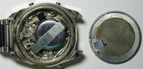
Printed circuit board
The device is assembled on a double-sided round-shaped printed circuit board to fit the inner diameter of a wristwatch case. But in the manufacture I used two single-sided boards with a thickness of 0.35 mm. This thickness was again obtained by peeling it from a double-sided fiberglass with a thickness of 1.5 mm. Then he glued the boards. All this was done because I did not have a thin double-sided fiberglass, and each saved millimeter of thickness in the limited internal space of the watch case is very valuable, and there was no need to combine it in the manufacture of printed conductors using the LUT method. The PCB drawing and the location of the parts are in the attached files. On one side there are indicators and current-limiting resistors R1-R8. On the back - all the other details. There are two through holes for white and infrared LEDs.
The contacts of the buttons and the battery holder are made of flexible, springy sheet steel with a thickness of 0.2 ... 0.3 mm. and tinned. Below are photos of the board from both sides:


Construction, parts and their possible replacement
Microcontroller ATmega168PA-AU can be replaced with ATmega168P-AU, ATmega168V-10AU ATmega168-20AU. Digital indicators - 4 pieces KPSA02-105 super bright red color with a height of 5.08 mm. Can be supplied from the same series KPSA02-xxx or KCSA02-xxx. (just not green - they will glow faintly) I do not know of other analogs of similar sizes with decent brightness. In HG1, HG3, the cathode connection of the segments differs from HG2, HG4, because it was more convenient for me to lay out the printed circuit board. In this regard, a different character generator table is used for them in the program. Used resistors and capacitors SMD for surface mounting of standard sizes 0805 and 1206, LEDs D1-D7 of standard size 0805. White and infrared LEDs with a diameter of 3mm. The board has 13 through holes where you need to install jumpers. A DS18B20 with a 1-Wire interface was used as a temperature sensor. LS1 is a conventional piezoelectric sounder that fits into the lid. With one contact, it connects to the board with the help of a spring installed on it, with the other it connects to the watch case by the lid itself. Quartz resonator from a wristwatch.
Programming, firmware, fuses
For in-circuit programming, the board has only 6 round contact pins (J1), since a full-fledged connector does not fit in height. I connected them to the programmer using a contact device made of a PLD2x3 pin plug and soldered onto them with springs, pressing them with one hand to the spots. Below is a photo of the device.
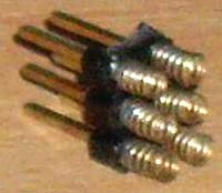
I used it because during the debugging process I had to reflash the MK many times. With a one-time firmware, it is easier to solder thin wires connected to the programmer to the patches, and then unsolder again. It is more convenient to flash the MK without a battery, but so that the power comes either from an external + 3V source, or from a programmer with the same supply voltage. The program is written in assembler in the VMLAB 3.15 environment. Source codes, firmware for FLASH and EEPROM in the application.
FUSE bits of microcontroller DD1 must be programmed as follows:
CKSEL3 ... 0 = 0010 - clocking from the internal RC oscillator 8 MHz;
SUT1 ... 0 = 10 - Start-up time: 6 CK + 64 ms;
CKDIV8 = 1 - frequency divider by 8 is disabled;
CKOUT = 1 - Output Clock on CKOUT is disabled;
BODLEVEL2… 0 = 111 - supply voltage control is disabled;
EESAVE = 0 - erasing the EEPROM during chip programming is prohibited;
WDTON = 1 - No constant activation of Watchdog Timer;
It is better not to touch the rest of the FUSE bits. FUSE – bit is programmed if set to “0”.
EEPROM flashing with the dump enclosed in the archive is required.
The first EEPROM cells contain the initial parameters of the device. The table below describes the purpose of some of them, which can be changed within reasonable limits.
|
Cell address |
Appointment |
Parameter |
Note |
|
|
The amount of battery voltage at which a low battery signal occurs |
260 ($ 104) (2.6V) |
|||
|
coefficient for correcting the value of the measured battery voltage |
||||
|
time interval for transition to sleep mode |
1 unit = 1 sec |
|||
|
time interval for switching to sleep mode when the flashlight is on |
1 unit = 1 sec |
|||
|
time interval for switching to sleep mode when in remote control mode for cameras |
1 unit = 1 sec |
|||
|
This is where the IButton key numbers are stored. |
Small explanations for the points:
1 point. The value of the voltage on the battery is indicated here, at which the LED will light up, signaling its low value. I set it to 2.6V (parameter - 260). If you need something else, for example 2.4V, then you need to write 240 ($ 00F0). The low byte is entered into the cell at $ 0000, and the high byte, respectively, in $ 0001.
2 point. Since I did not install a variable resistor on the board to adjust the accuracy of the battery voltage measurement due to lack of space, I introduced software calibration. The calibration procedure for accurate measurement is as follows: initially, a factor of 1024 ($ 400) is written in this EEPROM cell, you need to put the device in active mode and look at the voltage on the indicator, and immediately measure the real voltage on the battery with a voltmeter. The correction factor (K), which must be set, is calculated by the formula: K = Uр / Ui * 1024 where Uр is the real voltage measured by a voltmeter, Ui is the voltage measured by the device itself. After calculating the "K" factor, it is entered into the device (as described in the operating instructions). After calibration, my error did not exceed 3%.
3 pips Here you can set the time after which the device goes into sleep mode if no buttons are pressed. It costs me 16 seconds. If you need to fall asleep after 30 seconds, then you need to write down 30 ($ 26).
The 4 and 5 points are the same.
6 pips The address $ 0030 stores the zero key family code (dallas 1-Wire), then its 48-bit number and CRC. And so 50 keys in series.
Setting, work features
Setting up the device comes down to calibrating the battery voltage measurement as described above. It is also necessary to detect the deviation of the clock in 1 hour, calculate and enter the corresponding correction value (the procedure is described in the operating instructions).
The device is powered by a CR2032 (3V) lithium battery and consumes about 4 μA in sleep mode, and 5 ... 20 mA in active mode, depending on the brightness of the indicator. With a daily five-minute use of the active mode, the battery should be enough for about 2 ... .8 months, depending on the brightness. The watch case is connected to the minus of the battery.
Key reading was checked on DS1990. Emulation is tested on METAKOM intercoms. Serial numbers from 46 to 49 (last 4) are stitched (all keys are stored in EEPROM, they can be changed before flashing) universal keys for intercoms. The key registered at number 49 opened all METAKOM intercoms that I came across, the rest of the universal keys could not be tested, I took their codes from the network.
Remote control for cameras tested on Pentax optio L20, Nikon D3000. Canon could not get it to check.
The user manual is 13 pages long, so I did not include it in the article, but put it in the attachment in PDF format.

The archive contains:
Scheme in and GIF;
Drawing of the printed circuit board and the arrangement of elements in the format;
Firmware and sources in assembler;
List of radioelements
| Designation | A type | Denomination | Quantity | Note | Score | My notebook |
|---|---|---|---|---|---|---|
| DD1 | MK AVR 8-bit | ATmega168PA | 1 | PA-AU | Into notepad | |
| U2 | temperature sensor | DS18B20 | 1 | Into notepad | ||
| Q1 | MOSFET transistor | 2N7002 | 1 | Into notepad | ||
| C1, C2 | Capacitor | 30 pF | 2 | Into notepad | ||
| C3, C4 | Capacitor | 0.1 uF | 2 | Into notepad | ||
| C5 | Electrolytic capacitor | 47 uF | 1 | Into notepad | ||
| R1-R8, R17 | Resistor | 100 ohm | 9 | Into notepad | ||
| R9 | Resistor | 10 kΩ | 1 | Into notepad | ||
| R10 | Resistor | 8.2 Ohm | 1 | Into notepad | ||
| R11 | Resistor | 300 Ohm | 1 | Into notepad | ||
| R12 | Resistor | 2 MOhm | 1 | Into notepad | ||
| R13 | Resistor | 220 kΩ | 1 | Into notepad | ||
| R14 | Resistor | 30 kΩ | 1 | Into notepad | ||
| R15, R19 | Resistor | 4.7 k Ohm | 2 | Into notepad | ||
| R16 | Resistor | 20 kΩ | 1 |
Homemade electronic clock, element base - part 1, measuring time
- DIY or do it yourself
Probably every geek who is fond of homemade electronics sooner or later comes up with the idea of making his own, unique, watch. The idea is quite good, let's figure out how and on what it is better to make them. As a starting point, we will assume that a person knows how to program microcontrollers, understands how to send 2 bytes via an i2c or serial port, and can solder several wires together. In principle, this is enough.
It is clear that the key function of the watch is the measurement of time (who would have thought, huh?). And it is desirable to do this as accurately as possible, there are several options and pitfalls.
So, what methods of time measurement available in hardware can we use?
Built-in RC generator of the processor
The simplest idea that can come to mind is to simply set up a software timer and count down the seconds with it. Now, this idea is no good. The clock, of course, will work, only the accuracy of the built-in generator is not regulated in any way, and can "float" within 10% of the nominal value. Hardly anyone needs a watch that takes 15 minutes a month.DS1307 Real Time Module
A more correct option, which is also used in most "folk" products, is a real-time clock. The microcircuit communicates with the microcontroller via I2C, requires a minimum of strapping (quartz and a pair of resistors). The price of the issue is about 100 rubles for a microcircuit, or about $ 1 for an ebee for a ready-made board with a microcircuit, a memory module and a battery connector.Scheme from the datasheet:
Equally important, the microcircuit is available in a DIP package, which means that any novice radio amateur can solder it. The built-in battery keeps the watch running even when the power has been turned off.
It would seem that everything is fine if it were not for one problem - low accuracy. The approximate accuracy of watch quartz is 20-30ppm. Ppm - parts per million, shows the number of parts per million. It would seem that 20 millionth is super, but for a frequency of 32768Hz it turns out 20 * 32768/1000000 = ± 0.65536Hz, i.e. already half a hertz. By simple calculations, it can be seen that the generator with such a difference per day "hits" extra (or missing) 56 thousand cycles, which corresponds to 2 seconds a day. Quartzs are different, some users wrote about an error of 5 seconds a day. Somehow not very accurate - in a month such hours will go away at least for a minute. This is already a decent difference, noticeable with the naked eye (when the grandmother's favorite TV series starts at 11.00, and the clock shows 11.05, the developer of such a watch in front of relatives will be uncomfortable).
However, since the room temperature is more or less stable, and the quartz frequency will not change much, you can add software correction. Another advice given on the forums is to use watch quartz from old motherboards, according to reviews, they are quite accurate there.
DS3231 Real Time Module
We are not the first to ask the question of accuracy, and the Dallas company has met the wishes and released a more advanced module - DS3231. It is called "Extremely Accurate Real Time Clock" and has a built-in temperature compensated generator. The accuracy is 10 times higher at 2ppm. The price of the issue is slightly higher, but the microcircuit case is designed for SMD-mounting, it is not so convenient to solder, but you can buy a ready-made board on ebee.
(photo from the seller's website)
Accuracy of 6 seconds per month is already a good result. But let's go further - ideally, the clock in the 21st century does not need to be adjusted at all.
DCF-77 radio module
The method is rather exotic, but for the sake of completeness, it should be mentioned. Few people know, but exact time signals have been transmitted by radio since the 70s. The DCF-77 transmitter is located in Germany near Frankfurt, and precise time stamps are transmitted on the VLF frequency of 77.5KHz (yes, they had wall and table clocks already 20 years ago, which do not need to be adjusted).The method is good in that the circuit has low power consumption, so now even wristwatches with this technology are being produced. A ready-made DCF-77 reception board can be bought on ebay, the issue price is $ 20.

Many clocks and weather stations have the ability to receive DCF-77, the only problem is that the signal practically does not reach Russia. Coverage map from Wikipedia:

As you can see, only Moscow and St. Petersburg are on the border of the reception area. According to the owners, only sometimes the signal can be received, which, of course, is not suitable for practical use.
GPS module
If the clock will stand near the window, then a very real method of obtaining the exact time is a GPS module. These modules can be bought inexpensively on ebay (issue price 10-15 $). For example, Ublox NEO-6M connects directly to the processor serial pins and outputs NMEA strings at 9600.
The data comes in approximately the following format "$ GPRMC, 040302.663, A, 3939.7, N, 10506.6, W, 0.27,358.86,200804, * 1A", and it is not difficult to parse it even for a weak Arduino. Patriots, by the way, can purchase the more expensive Ublox NEO-7N module, which supports (according to reviews) both GPS and Glonass.
Obviously, the GPS-module does not know anything about different time zones, so the developer will have to think over their calculation and change of summer / winter time. Another disadvantage of using GPS is relatively high power consumption (however, some modules can be put into "sleep mode" by separate commands).
Wi-Fi
And finally, the last (and most obvious at the moment) way to get the exact time is to take it from the Internet. There are two approaches here. The first, and most simple, is to use something like a Raspberry PI with Linux as a clock board, then you don't need to do anything, everything will work out of the box. If you want something exotic, the esp8266 module is the most interesting option.
This is an inexpensive (the issue price is about 200 rubles on ebay), the WiFi module can exchange with the server via the serial port of the processor, if desired, it can also be reflashed (there are quite a lot of third-party firmware), and some of the logic (for example, polling the time server) can be done in the module itself. A lot of everything is supported by third-party firmware, from Lua to C ++, so there are quite enough options to "stretch your brains".
On this topic, the measurement of time can probably be closed. In the next part, we will take a closer look at processors and ways to display time.
Self-made wristwatch on a vacuum indicator, made in steampunk style. Material taken from www.johngineer.com. This wristwatch is based on the IVL-2 display. Initially I bought several of these indicators to create a standard table clock, but after reflection I realized that you can build a stylish wristwatch too. The indicator has a number of features that make it more suitable for this purpose than most other Soviet displays. Here are the parameters:
- The nominal filament current is 60mA 2.4V, but works with 35mA 1.2V.
- Small size - only 1.25 x 2.25 "
- Can work with relatively low grid voltage 12V (up to 24)
- Only consumes 2.5mA / segment at 12.5V
All pictures can be made larger by clicking on them. The biggest obstacle to the successful completion of the project was food. Since this watch was conceived as part of a suit, it doesn't matter that the battery lasts only 10 hours. Stopped for AA and AAA.

The circuit is pretty simple. Atmel AVR ATMega88 microcontroller, and real-time clock - DS3231. But there are other ICs, much cheaper, that will work just as well in a generator.
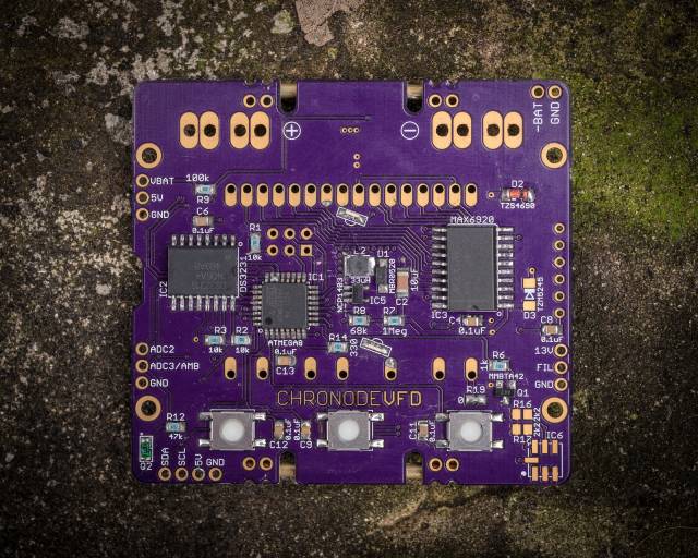
The VFD is driven by the MAX6920 - 12-bit shift register with high voltage (up to 70V) outputs. It is easy to use, very reliable and compact. It is also possible for the display driver to solder a bunch of discrete components together, but this was impractical due to space constraints.

The battery voltage also powers the 5V boost converter (MCP1640 SOT23-6), which is required for the AVR, DS3231, and MAX6920 to operate properly, and also acts as an input voltage for the second boost converter (NCP1403 SOT23-5), which produces 13V for grid voltage of the vacuum indicator.

The watch has three sensors: one analog and two digital. The analog sensor is a phototransistor and is used to detect the light level (Q2). Digital sensors: BMP180 - pressure and temperature, and MMA8653 - accelerometer for motion detection. Both digital sensors are connected via the I2C bus to the DS3231.

Brass tubes are soldered to beauty and protect the glass display of the wristwatch, and 2mm thick copper wires are used to attach the leather strap. The complete schematic diagram is not given in the original article - see the connection via datasheets to the indicated microcircuits.
Even in my youth, I wanted to collect an electronic clock. It seemed to me that assembling the watch was the pinnacle of skill. As a result, I assembled a watch with a calendar and an alarm clock on the K176 series. Now they are already morally outdated and I wanted to collect something more modern. After a long search on the Internet (I never thought it was so hard for me to please;)) I liked this scheme. The difference from the above diagram is that a rare microcircuit is not used. TRIC6B595, and its composite and more powerful analogue on microcircuits 74HC595 and ULN2003... The fixes to the circuit are shown below.
Diagram of electronic LED clock creeping line
The author of the scheme dear OLED, the firmware is also his. The clock displays the current time, year, month and day of the week, as well as the temperature outside and inside the house with scrolling text. They have 9 independent alarms. It is possible to adjust (correct) the stroke + - a minute per day, select the speed of the line, change the brightness of the LEDs, depending on the time of day.

In the event of a power outage, the clock is powered either from an ultracapacitor (1 Farad capacity is enough for 4 days of power), or from a battery. Anyone who likes it, the board is designed to install both. They have a very convenient and intuitive control menu (all control is done with just two buttons). The following parts are used in the watch (all parts are in SMD cases):
Microcontroller AtMEGA 16A
-
Shift register 74HC595
-
Chip ULN2803(eight Darlington keys)
-
Temperature sensors DS18B20(installed as an option)
-
25 resistors 75 Ohm (standard 0805)
-
3 resistors 4.7kOhm
-
2 resistors 1.5 kOhm
-
1 resistor 3.6 kOhm
-
6 SMD capacitors with a capacity of 0.1 μF
-
1 capacitor 220 uF
-
Watch quartz for a frequency of 32768 hertz.
-
Matrices 3 pieces of brand 23088-ASR 60x60 mm - common cathode
-
Any boozer for 5 volts.


Printed circuit board for electronic LED clock creeping line
For residents of Ukraine, I will tell you, the matrices are in the store of the Lugansk radio market. The advantages of watches over other similar devices are the minimum of parts and high repeatability. The LED clock starts working immediately after the firmware, unless of course there are no jambs in the installation. The microcontroller is flashed in-circuit; for this, special pins are provided on the board. I was flashing with the Ponyprog program. Fuses screens for programs ponyprog and AVR are given below, the firmware files in Ukrainian and Russian are also posted, who is more familiar with what.

If you do not need temperature sensors, then they can be omitted. The watch automatically recognizes the connection of sensors, and if one or both sensors are missing, then the device simply stops displaying the temperature (if one sensor is missing, then the outside temperature is not displayed, if both, then the temperature is not displayed at all).
Homemade LED watch case


To demonstrate the work of the clock, a video is given, it is not of high quality, since it was filmed with a camera, but what is there.
Watch video
Four copies of these watches have already been collected, I present each one to relatives for their birthday. And everyone liked them very much. If you also wanted to collect this watch and have any questions, you are welcome to our forum. Respectfully yours, Sergei Voitovich ( Sergey-78 ).
Discuss the article LED ELECTRONIC CLOCK
Hello geektimes! In the first part of the article, the principles of obtaining the exact time on a homemade watch were considered. Let's go further and consider how and on what it is better to display this time.
1. Output devices
So, we have a certain platform (Arduino, Raspberry, PIC / AVR / STM controller, etc), and the task is to connect some indication to it. There are many options that we will consider.Segment display
Everything is simple here. The segment indicator consists of ordinary LEDs, which are banally connected to the microcontroller through damping resistors.Watch out for traffic!
Pros: simplicity of design, good viewing angles, low price.
Minus: the amount of information displayed is limited.
There are two types of indicator designs, with a common cathode and a common anode, inside it looks something like this (diagram from the manufacturer's website). 
There are 1001 articles on how to connect an LED to a microcontroller, google for help. Difficulties begin when we want to make a large clock - after all, looking at a small indicator is not particularly convenient. Then we need indicators like this (photo from eBay): 
They are powered by 12V, and simply will not work directly from the microcontroller. Here the microcircuit comes to the rescue CD4511, just for this purpose. It not only converts the data from the 4-bit line into the desired digits, but also contains a built-in transistor switch to supply voltage to the indicator. Thus, in the circuit we will need to have a "power" voltage of 9-12V, and a separate step-down converter (for example, L7805) to power the "logic" of the circuit.
Matrix indicators
In fact, these are the same LEDs, only in the form of an 8x8 matrix. Photos from eBay:
Sold on eBay as single modules or ready-made blocks, for example, 4 pieces. Their control is very simple - a microcircuit is already soldered on the modules MAX7219, ensuring their operation and connection to the microcontroller with just 5 wires. There are many libraries for Arduino, those interested can look at the code.
Pros: low price, good viewing angles and brightness.
Minus: low resolution. But for the task of outputting the time is quite enough.
LCD indicators
LCD indicators are graphical and textual.
Graphics are more expensive, but they allow you to display more varied information (for example, a graph of atmospheric pressure). Text messages are cheaper and easier to work with, they also allow you to display pseudo-graphics - you can load custom symbols into the display.
It is not difficult to work with the LCD indicator from the code, but there is a certain disadvantage - the indicator requires many control lines (from 7 to 12) from the microcontroller, which is inconvenient. Therefore, the Chinese came up with the idea of combining the LCD indicator with the i2c controller, it turned out in the end it is very convenient - only 4 wires are enough to connect (photo from eBay). 
LCD indicators are quite cheap (if taken on eBay), large, easy to connect, and you can display a variety of information. The only drawback is not very large viewing angles.
OLED indicators
They are an improved continuation of the previous version. They range from small and cheap 1.1 "to large and expensive. Photo from eBay.
Actually, they are good for everyone except the price. As for small indicators, 0.9-1.1 "in size, it is difficult to find any practical application for them (except for studying working with i2c).
Gas discharge indicators (IN-14, IN-18)
These indicators are now very popular, apparently due to the "warm lamp sound of light" and the originality of the design.
(photo from the site nocrotec.com)
Their wiring diagram is somewhat more complicated, since these indicators use 170V for ignition. Converter from 12V => 180V can be made on a microcircuit MAX771... To supply voltage to the indicators, a Soviet microcircuit is used K155ID1, which was specially created for this. The price of the issue for self-production: about 500 rubles for each indicator and 100 rubles for the K155ID1, all other details, as they wrote in old magazines, "are not in short supply." The main difficulty here is that both IN-xx and K155ID1 have long been out of production, and you can buy them only on radio markets or in a few specialized stores.
2. Choice of platform
We have more or less figured out the indication, it remains to decide which hardware platform is better to use. There are several options (I do not consider homemade ones, because those who know how to wire a board and solder a processor do not need this article).Arduino
The easiest option for beginners. The ready-made board is inexpensive (about $ 10 on eBay with free shipping), has all the necessary connectors for programming. Photos from eBay:
There are a huge number of different libraries for Arduino (for example, for the same LCD screens, real-time modules), Arduino is hardware compatible with various additional modules.
The main disadvantage: the complexity of debugging (only through the serial port console) and a rather weak processor by modern standards (2KB of RAM and 16MHz).
The main plus: you can do a lot of things, practically without bothering with soldering, buying a programmer and wiring boards, the modules just need to be connected to each other.
32-bit STM processors
For those who want something more powerful, there are ready-made boards with STM processors, for example, a board with an STM32F103RBT6 and a TFT screen. Photos from eBay:
Here we already have full debugging in a full-fledged IDE (out of all the different ones I liked Coocox IDE more), however, we need a separate ST-LINK debugger-programmer with a JTAG connector (the issue price is $ 20-40 on eBay). Alternatively, you can buy an STM32F4Discovery debug board, which already has this programmer built-in, and can be used separately.
Raspberry PI
And finally, for those who want full integration with the modern world, there are single-board computers with Linux, everyone probably already knows Raspberry PI. Photos from eBay:
This is a full-fledged computer with Linux, a gigabyte of RAM and a 4-core processor on board. On the edge of the board, there is a panel of 40 pins, which allows you to connect various peripherals (pins are available from the code, for example, in Python, not to mention C / C ++), there is also a standard USB in the form of 4 connectors (you can connect WiFi). There is also standard HDMI.
The power of the board will be enough, for example, not only to display the time, but also to keep an HTTP server for setting parameters via the web interface, load the weather forecast via the Internet, and so on. In general, there is a lot of room for a flight of imagination.
With the Raspberry (and STM32 processors), there is only one difficulty - its pins use 3-volt logic, and most external devices (for example, LCD screens) work the old-fashioned way from 5V. You can, of course, connect and so, in principle, it will work, but this is not quite the correct method, and it’s a pity to spoil the $ 50 payment. The correct way is to use a "logic level converter", which costs only $ 1-2 on eBay.
Photos from eBay: 
Now it is enough to connect our device through such a module, and all parameters will be coordinated.
ESP8266
The method is rather exotic, but rather promising due to the compactness and low cost of the solution. For very little money (about $ 4-5 on eBay), you can buy an ESP8266 module containing a processor and WiFi on board.Photos from eBay:

Initially, such modules were intended as a WiFi bridge for exchange via a serial port, but enthusiasts have written many alternative firmwares that allow working with sensors, i2c devices, PWM, etc. Hypothetically, it is quite possible to receive time from an NTP server and output it via i2c on the display. For those who want to connect a lot of different peripherals, there are special NodeMCU boards with a large number of pins, the issue price is about 500 rubles (of course on eBay): 
The only drawback is that the ESP8266 has very little RAM memory (depending on the firmware, from 1 to 32KB), but this makes the task even more interesting. The ESP8266 modules use 3-volt logic, so the above level converter comes in handy here as well.
On this, the introductory excursion into homemade electronics can be completed, the author wishes everyone successful experiments.
Instead of a conclusion
In the end, I settled on using a Raspberry PI with a text indicator configured to work with pseudo-graphics (which turned out to be cheaper than a graphical screen of the same diagonal). I took a picture of the desktop clock screen while writing this article.
The clock displays the exact time taken from the Internet, and the weather that is updated from Yandex, all this is written in Python, and has been working for several months already. In parallel, an FTP server is launched on the watch, which allows (together with port forwarding on the router) to update the firmware on them not only from home, but also from anywhere where there is Internet. As a bonus, Raspberry's resources are, in principle, enough to connect a camera and / or microphone with the ability to remotely monitor an apartment, or to control various modules / relays / sensors. You can add all sorts of "goodies", such as LED indication of incoming mail, and so on.
PS: Why eBay?
As you can see, prices or photos from ebay were given for all devices. Why is that? Unfortunately, our stores often live according to the principle "I bought for 1 $, sold for 3, and I live on this 2 percent." As a simple example, the Arduino Uno R3 costs (at the time of this writing) 3600r in St. Petersburg, and 350r on eBay with free shipping from China. The difference is really an order of magnitude, without any literary exaggeration. Yes, you will have to wait a month to pick up the parcel at the post office, but I think such a difference in price is worth it. But however, if someone needs it right now and urgently, then probably there is a choice in local stores, here everyone decides for himself.