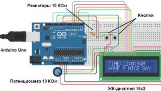
How to create a robot?


When it comes to robots, we imagine a giant machine with artificial intelligence, as in the films about RoboCop, etc. However, a robot does not have to be a large and technically complex device. In this article we will tell you how to create a robot at home. Having created your own mini-robot, you will be convinced that no special knowledge or tools are required for this.
Materials for work
So, we create a robot with our own hands, having prepared the following materials for construction:
- 2 small pieces of wire.
- 1 small toy motor 3 Volt.
- 1 AA battery.
- 2 beads.
- 2 small square pieces of polystyrene foam of different sizes.
- Glue gun.
- Material for the legs (paper clips, toothbrush head, etc.).
Instructions for creating a robot
Now let's move on to a step-by-step description of how to create a robot:
- Glue the larger piece of styrofoam to the toy motor to the side with the metal contacts on top. This is necessary to protect the contacts from moisture.
- Glue a battery on top of a piece of polystyrene foam.
- Glue a second piece of polystyrene foam to the back of the engine to create a slight weight imbalance. It is thanks to this imbalance that the robot will be able to move. Let the glue dry.
- Glue the legs to the engine. In order for the legs to hold as firmly as possible, you will first need to glue small pieces of polystyrene foam to the engine, and then glue the legs to them.
- The wire to the motor can either be taped or soldered. The second option is more preferable - this way the robot will last much longer. Both pieces of wire must be soldered to the metal contacts on the motor as tightly as possible.
- Next, you will need to attach any of the pieces of wire to one of the sides of the battery, to the “plus” or to the “minus”. It can be attached to the battery either with electrical tape or with a glue gun. Fastening with glue is more reliable, but you need to be as careful as possible when applying it, since if you use too much glue, the contact between the wire and the battery will be lost.
- Glue beads to the battery to simulate eyes.
- Connect the second piece of wire to the other end of the battery to power the robot. IN in this case It is better to use electrical tape rather than glue. This way you can easily open the contact and stop the robot when you get tired of it.
Such a robot will last exactly as long as the battery charge lasts. As you can see, creating robots at home is a rather exciting process in which there is nothing complicated. Of course, you can later try to create more complex, programmable models. However, to create them you will need certain knowledge and Additional materials, which are sold in an electrical store. The same toy mini-robot can be easily made together with your child in a matter of minutes.
Today we will tell you how to make a robot from available materials. The resulting “high-tech android,” although it will be small size and is unlikely to be able to help you with housework, but will certainly amuse both children and adults.
Necessary materials
In order to make a robot with your own hands, you do not need knowledge of nuclear physics. This can be done at home from ordinary materials that you always have on hand. So what we need:- 2 pieces of wire
- 1 motor
- 1 AA battery
- 3 push pins
- 2 pieces of foam board or similar material
- 2-3 heads of old toothbrushes or a few paper clips

1. Attach the battery to the motor
Using a glue gun, attach a piece of foam cardboard to the motor housing. Then we glue the battery to it.


At the very end of the destabilizer, drop a couple of drops of glue, or attach some decorative element - this will add individuality to our creation and increase the amplitude of its movements.

3. Legs
Now you need to equip the robot with lower limbs. If you use toothbrush heads for this, glue them to the bottom of the motor. You can use the same foam board as a layer.


5. Battery connection
Using a heat gun, glue the wire to one end of the battery. You can choose any of the two wires and either side of the battery - polarity does not matter in this case. If you're good at soldering, you can also use soldering instead of glue for this step.

6. Eyes
A pair of beads, which we attach with hot glue to one end of the battery, are quite suitable as the robot’s eyes. At this step, you can show your imagination and come up with appearance eye at your discretion.
7. Launch
Now let's bring our homemade product to life. Take the free end of the wire and attach it to the unoccupied battery terminal using adhesive tape. You shouldn't use hot glue for this step because it will prevent you from turning off the motor if necessary.Make a robot very simple Let's figure out what it takes to create a robot at home, in order to understand the basics of robotics.
Surely, after watching enough movies about robots, you have often wanted to build your own comrade in battle, but you didn’t know where to start. Of course, you won't be able to build a bipedal Terminator, but that's not what we're trying to achieve. Collect simple robot anyone who knows how to hold a soldering iron correctly in their hands can do it and this does not require deep knowledge, although it will not hurt. Amateur robotics is not much different from circuit design, only much more interesting, because it also involves areas such as mechanics and programming. All components are easily available and are not that expensive. So progress does not stand still, and we will use it to our advantage.
Introduction
So. What is a robot? In most cases this automatic device, which reacts to any actions environment. Robots can be controlled by humans or perform pre-programmed actions. Typically, the robot is equipped with a variety of sensors (distance, rotation angle, acceleration), video cameras, and manipulators. Electronic part The robot consists of a microcontroller (MC) - a microcircuit that contains a processor, a clock generator, various peripherals, RAM and permanent memory. There is a world great amount a variety of microcontrollers for different applications and on their basis you can assemble powerful robots. They are widely used for amateur buildings. AVR microcontrollers. They are by far the most accessible and on the Internet you can find many examples based on these MKs. To work with microcontrollers you need to be able to program in assembler or C and have basic knowledge in digital and analog electronics. In our project we will use C. Programming for MK is not much different from programming on a computer, the syntax of the language is the same, most functions are practically no different, and new ones are quite easy to learn and convenient to use.
What do we need
To begin with, our robot will be able to simply avoid obstacles, that is, repeat the normal behavior of most animals in nature. Everything we need to build such a robot can be found in radio stores. Let's decide how our robot will move. I consider the most successful tracks to be those used in tanks; these are the most convenient solution, because the tracks have greater maneuverability than the wheels of the car and are more convenient to control (to turn, it is enough to rotate the tracks in different sides). Therefore, you will need any toy tank whose caterpillars rotate independently of each other, this can be bought at any toy store for reasonable price. From this tank you only need a platform with tracks and motors with gearboxes, the rest you can safely unscrew and throw away. We also need a microcontroller, my choice fell on ATmega16 - it has enough ports for connecting sensors and peripherals and in general it is quite convenient. You will also need to purchase some radio components, a soldering iron, and a multimeter.
Making a board with MK
In our case, the microcontroller will perform the functions of the brain, but we will not start with it, but with powering the robot’s brain. Proper nutrition- a guarantee of health, so we will start with how to properly feed our robot, because this is where novice robot builders usually make mistakes. And in order for our robot to work normally, we need to use a voltage stabilizer. I prefer the L7805 chip - it is designed to produce a stable 5V output voltage, which is what our microcontroller needs. But due to the fact that the voltage drop on this microcircuit is about 2.5V, a minimum of 7.5V must be supplied to it. Used together with this stabilizer electrolytic capacitors to smooth out voltage ripples, a diode must be included in the circuit to protect against polarity reversal.
Now we can move on to our microcontroller. The case of the MK is DIP (it’s more convenient to solder) and has forty pins. On board there is an ADC, PWM, USART and much more that we will not use for now. Let's look at a few important nodes. The RESET pin (9th leg of the MK) is pulled up by resistor R1 to the “plus” of the power source - this must be done! Otherwise, your MK may unintentionally reset or, more simply put, glitch. Also a desirable measure, but not mandatory, is to connect RESET via ceramic capacitor C1 to ground. In the diagram you can also see a 1000 uF electrolyte; it saves you from voltage dips when the engines are running, which will also have a beneficial effect on the operation of the microcontroller. Quartz resonator X1 and capacitors C2, C3 should be located as close as possible to pins XTAL1 and XTAL2.
I won’t talk about how to flash MK, since you can read about it on the Internet. We will write the program in C; I chose CodeVisionAVR as the programming environment. This is a fairly user-friendly environment and is useful for beginners because it has a built-in code creation wizard.

Motor control
No less an important component Our robot has a motor driver that makes it easier for us to control it. Never and under no circumstances should motors be connected directly to the MK! At all powerful loads You cannot control it from the microcontroller directly, otherwise it will burn out. Use key transistors. For our case, there is a special chip - L293D. In such simple projects, always try to use this particular chip with the “D” index, as it has built-in diodes for overload protection. This microcircuit is very easy to control and is easy to get in radio stores. It is available in two packages: DIP and SOIC. We will use DIP in the package due to the ease of mounting on the board. L293D has separate power supply for motors and logic. Therefore, we will power the microcircuit itself from the stabilizer (VSS input), and the motors directly from the batteries (VS input). L293D can withstand a load of 600 mA per channel, and it has two of these channels, that is, two motors can be connected to one chip. But to be on the safe side, we will combine the channels, and then we will need one micra for each engine. It follows that the L293D will be able to withstand 1.2 A. To achieve this, you need to combine the micra legs, as shown in the diagram. The microcircuit works as follows: when a logical “0” is applied to IN1 and IN2, and a logical one is applied to IN3 and IN4, the motor rotates in one direction, and if the signals are inverted - a logical zero is applied, then the motor will begin to rotate in the other direction. Pins EN1 and EN2 are responsible for turning on each channel. We connect them and connect them to the “plus” of the power supply from the stabilizer. Since the microcircuit heats up during operation, and installing radiators on this type of case is problematic, heat removal is ensured by GND legs - it is better to solder them on a wide contact pad. That's all you need to know about engine drivers for the first time.
Obstacle sensors
So that our robot can navigate and not crash into everything, we will install two infrared sensor. Most the simplest sensor consists of an IR diode that emits in the infrared spectrum and a phototransistor that will receive the signal from the IR diode. The principle is this: when there is no obstacle in front of the sensor, the IR rays do not hit the phototransistor and it does not open. If there is an obstacle in front of the sensor, then the rays are reflected from it and hit the transistor - it opens and current begins to flow. The disadvantage of such sensors is that they can react differently to different surfaces and are not protected from interference - the sensor may accidentally be triggered by extraneous signals from other devices. Modulating the signal can protect you from interference, but we won’t bother with that for now. For starters, that's enough.

Robot firmware
To bring the robot to life, you need to write firmware for it, that is, a program that would take readings from sensors and control the motors. My program is the simplest, it does not contain complex structures and will be understandable to everyone. The next two lines connect header files for our microcontroller and command for generating delays:
#include
#include
The following lines are conditional because the PORTC values depend on how you connected the motor driver to your microcontroller:
PORTC.0 = 1; PORTC.1 = 0; PORTC.2 = 1; PORTC.3 = 0; The value 0xFF means that the output will be log. "1", and 0x00 is log. "0". With the following construction we check whether there is an obstacle in front of the robot and on which side it is: if (!(PINB & (1< If light from an IR diode hits the phototransistor, then a log is installed on the microcontroller leg. “0” and the robot starts moving backward to move away from the obstacle, then turns around so as not to collide with the obstacle again and then moves forward again. Since we have two sensors, we check for the presence of an obstacle twice - on the right and on the left, and therefore we can find out which side the obstacle is on. The command "delay_ms(1000)" indicates that one second will pass before the next command begins to execute. I've covered most of the aspects that will help you build your first robot. But robotics doesn't end there. If you assemble this robot, you will have a lot of opportunities to expand it. You can improve the robot's algorithm, such as what to do if the obstacle is not on some side, but right in front of the robot. It also wouldn’t hurt to install an encoder - a simple device that will help you accurately position and know the location of your robot in space. For clarity, it is possible to install a color or monochrome display that can show useful information - battery charge level, distance to obstacles, various debugging information. It wouldn't hurt to improve the sensors - installing TSOPs (these are IR receivers that perceive a signal only of a certain frequency) instead of conventional phototransistors. In addition to infrared sensors, there are ultrasonic sensors, which are more expensive and also have their drawbacks, but have recently been gaining popularity among robot builders. In order for the robot to respond to sound, it would be a good idea to install microphones with an amplifier. But what I think is really interesting is installing the camera and programming machine vision based on it. There is a set of special OpenCV libraries with which you can program facial recognition, movement according to colored beacons and many other interesting things. It all depends only on your imagination and skills. List of components: ATmega16 in DIP-40 package> L7805 in TO-220 package L293D in DIP-16 housing x2 pcs. resistors with a power of 0.25 W with ratings: 10 kOhm x 1 pc., 220 Ohm x 4 pcs. ceramic capacitors: 0.1 µF, 1 µF, 22 pF electrolytic capacitors: 1000 µF x 16 V, 220 µF x 16 V x 2 pcs. diode 1N4001 or 1N4004 16 MHz quartz resonator IR diodes: any two of them will do. phototransistors, also any, but responding only to the wavelength of infrared rays Firmware code: At the moment my robot is almost complete. It is equipped with a wireless camera, a distance sensor (both the camera and this sensor are installed on a rotating tower), an obstacle sensor, an encoder, a signal receiver from the remote control and an RS-232 interface for connecting to a computer. It operates in two modes: autonomous and manual (receives control signals from the remote control), the camera can also be turned on/off remotely or by the robot itself to save battery power. I am writing firmware for apartment security (transferring images to a computer, detecting movements, walking around the premises). Surely, after watching enough movies about robots, you have often wanted to build your own comrade in battle, but you didn’t know where to start. Of course, you won't be able to build a bipedal Terminator, but that's not what we're trying to achieve. Anyone who knows how to hold a soldering iron correctly in their hands can assemble a simple robot and this does not require deep knowledge, although it will not hurt. Amateur robotics is not much different from circuit design, only much more interesting, because it also involves areas such as mechanics and programming. All components are easily available and are not that expensive. So progress does not stand still, and we will use it to our advantage. In our case, the microcontroller will perform the functions of the brain, but we will not start with it, but with powering the robot’s brain. Proper nutrition is the key to health, so we will start with how to properly feed our robot, because this is where novice robot builders usually make mistakes. And in order for our robot to work normally, we need to use a voltage stabilizer. I prefer the L7805 chip - it is designed to produce a stable 5V output voltage, which is what our microcontroller needs. But due to the fact that the voltage drop on this microcircuit is about 2.5V, a minimum of 7.5V must be supplied to it. Together with this stabilizer, electrolytic capacitors are used to smooth out voltage ripples and a diode is necessarily included in the circuit to protect against polarity reversal. #include The following lines are conditional because the PORTC values depend on how you connected the motor driver to your microcontroller: PORTC.0 = 1; The value 0xFF means that the output will be log. “1”, and 0x00 is log. "0". With the following construction we check whether there is an obstacle in front of the robot and on which side it is: If (!(PINB & (1< If light from an IR diode hits the phototransistor, then a log is installed on the microcontroller leg. “0” and the robot starts moving backward to move away from the obstacle, then turns around so as not to collide with the obstacle again and then moves forward again. Since we have two sensors, we check for the presence of an obstacle twice – on the right and on the left, and therefore we can find out which side the obstacle is on. The command "delay_ms(1000)" indicates that one second will pass before the next command begins to execute. MK type: ATmega16 #include Void main(void) //Configure output ports //Main loop of the program. Here we read the values from the sensors According to your wishes, I am posting a video: UPD. I re-uploaded the photos and made some minor corrections to the text. Now there are a great many opportunities that allow you to start creating robots without having any super-duper special knowledge. And it's great! Because it launches an avalanche of knowledge. And you don’t need to start with knowledge. Knowledge should not be the locomotive. Knowledge is the luggage that travels on this train. What then is the locomotive? And a locomotive is precisely the ignorance of how to do it so that something happens by itself. Building a robot is precisely the acquisition of such knowledge. In order not to get bogged down in examples, let's take just one example. The most trivial example. Let the robot move around the room without hitting the walls. What you need to know: 1. What will be the mechanics of movement. (Most robots have mechanics, but there are also incorporeal robots, for example, stock exchange robots.) If you do not have knowledge in this area, then immediately start acquiring it. What mechanisms are there for moving, on a flat surface, on an uneven surface, walking, on wheels... If you can’t make such a mechanism, find a ready-made one. Disassemble and reassemble it if possible. 2. How the robot will interact with the outside world. Here it would be good to have knowledge in radio electronics and/or information technology in order to understand how to read audio, optical, mechanical signals, how to receive information from the network (the latter is especially important for disembodied robots). The minimum knowledge is already sufficient; the missing knowledge must be filled in immediately. Fortunately, you can use a huge number of modular elements and sensors interfaced with ready-made controllers that turn the signals of these sensors simply into numbers. (if interested, you can discuss/exchange links/addresses in the comments where all this is purchased) 3. (most important) How the robot will think. It is necessary to decide what his “mental” activity consists of. For the selected example, this is just the ability to turn on and off N electric motors at the right times depending on the measured distance to the wall in front (at least). For mental activity, the robot needs a programmable unit with a microprocessor. There are many ready-made platforms for constructing robots (Arduino, Matryoshka, Strawberry Pi, Iskra, Troyka, etc. Again, I invite you to comment: share links, ask) The question immediately arises: does this mean you need to know programming? Strictly speaking yes. But among the listed platforms there are those in which programming is carried out in a visual environment without using any specific programming language. (That is, attention! You don’t need to know programming to start. But of course you need to know to continue) Here are the three main bones on which one must have the sinews of initial knowledge and skills, accessible even to a child, and on which to then build up the meat of higher engineering knowledge: Well, and finally, for inspiration, look (and this is not an advertisement, I have nothing to do with this manufacturer (share other examples)) what children's tools are for creating robotsConclusion

Introduction
So. What is a robot? In most cases, this is an automatic device that responds to any environmental actions. Robots can be controlled by humans or perform pre-programmed actions. Typically, the robot is equipped with a variety of sensors (distance, rotation angle, acceleration), video cameras, and manipulators. The electronic part of the robot consists of a microcontroller (MC) - a microcircuit that contains a processor, a clock generator, various peripherals, RAM and permanent memory. There are a huge number of different microcontrollers in the world for different applications, and on their basis you can assemble powerful robots. AVR microcontrollers are widely used for amateur buildings. They are by far the most accessible and on the Internet you can find many examples based on these MKs. To work with microcontrollers, you need to be able to program in assembler or C and have basic knowledge of digital and analog electronics. In our project we will use C. Programming for MK is not much different from programming on a computer, the syntax of the language is the same, most functions are practically no different, and new ones are quite easy to learn and convenient to use. What do we need
To begin with, our robot will be able to simply avoid obstacles, that is, repeat the normal behavior of most animals in nature. Everything we need to build such a robot can be found in radio stores. Let's decide how our robot will move. I think the most successful are the tracks that are used in tanks; this is the most convenient solution, because the tracks have greater maneuverability than the wheels of a vehicle and are more convenient to control (to turn, it is enough to rotate the tracks in different directions). Therefore, you will need any toy tank whose tracks rotate independently of each other, you can buy one at any toy store at a reasonable price. From this tank you only need a platform with tracks and motors with gearboxes, the rest you can safely unscrew and throw away. We also need a microcontroller, my choice fell on ATmega16 - it has enough ports for connecting sensors and peripherals and in general it is quite convenient. You will also need to purchase some radio components, a soldering iron, and a multimeter. Making a board with MK

Robot diagram
Now we can move on to our microcontroller. The case of the MK is DIP (it’s more convenient to solder) and has forty pins. On board there is an ADC, PWM, USART and much more that we will not use for now. Let's look at a few important nodes. The RESET pin (9th leg of the MK) is pulled up by resistor R1 to the “plus” of the power source - this must be done! Otherwise, your MK may unintentionally reset or, more simply put, glitch. Another desirable measure, but not mandatory, is to connect RESET through the ceramic capacitor C1 to ground. In the diagram you can also see a 1000 uF electrolyte; it saves you from voltage dips when the engines are running, which will also have a beneficial effect on the operation of the microcontroller. Quartz resonator X1 and capacitors C2, C3 should be located as close as possible to pins XTAL1 and XTAL2.
I won’t talk about how to flash MK, since you can read about it on the Internet. We will write the program in C; I chose CodeVisionAVR as the programming environment. This is a fairly user-friendly environment and is useful for beginners because it has a built-in code creation wizard.
My robot boardMotor control
An equally important component in our robot is the motor driver, which makes it easier for us to control it. Never and under no circumstances should motors be connected directly to the MK! In general, powerful loads cannot be controlled directly from the microcontroller, otherwise it will burn out. Use key transistors. For our case, there is a special chip - L293D. In such simple projects, always try to use this particular chip with the “D” index, as it has built-in diodes for overload protection. This microcircuit is very easy to control and is easy to get in radio stores. It is available in two packages: DIP and SOIC. We will use DIP in the package due to the ease of mounting on the board. L293D has separate power supply for motors and logic. Therefore, we will power the microcircuit itself from the stabilizer (VSS input), and the motors directly from the batteries (VS input). L293D can withstand a load of 600 mA per channel, and it has two of these channels, that is, two motors can be connected to one chip. But to be on the safe side, we will combine the channels, and then we will need one micra for each engine. It follows that the L293D will be able to withstand 1.2 A. To achieve this, you need to combine the micra legs, as shown in the diagram. The microcircuit works as follows: when a logical “0” is applied to IN1 and IN2, and a logical one is applied to IN3 and IN4, the motor rotates in one direction, and if the signals are inverted and a logical zero is applied, then the motor will begin to rotate in the other direction. Pins EN1 and EN2 are responsible for turning on each channel. We connect them and connect them to the “plus” of the power supply from the stabilizer. Since the microcircuit heats up during operation, and installing radiators on this type of case is problematic, heat removal is ensured by GND legs - it is better to solder them on a wide contact pad. That's all you need to know about engine drivers for the first time. Obstacle sensors
So that our robot can navigate and not crash into everything, we will install two infrared sensors on it. The simplest sensor consists of an IR diode that emits in the infrared spectrum and a phototransistor that will receive the signal from the IR diode. The principle is this: when there is no obstacle in front of the sensor, the IR rays do not hit the phototransistor and it does not open. If there is an obstacle in front of the sensor, then the rays are reflected from it and hit the transistor - it opens and current begins to flow. The disadvantage of such sensors is that they can react differently to different surfaces and are not protected from interference - the sensor may accidentally be triggered by extraneous signals from other devices. Modulating the signal can protect you from interference, but we won’t bother with that for now. For starters, that's enough. 
The first version of my robot's sensorsRobot firmware
To bring the robot to life, you need to write firmware for it, that is, a program that would take readings from sensors and control the motors. My program is the simplest, it does not contain complex structures and will be understandable to everyone. The next two lines include header files for our microcontroller and commands for generating delays:
#include
PORTC.1 = 0;
PORTC.2 = 1;
PORTC.3 = 0;
...
} Conclusion
I've covered most of the aspects that will help you build your first robot. But robotics doesn't end there. If you assemble this robot, you will have a lot of opportunities to expand it. You can improve the robot's algorithm, such as what to do if the obstacle is not on some side, but right in front of the robot. It also wouldn’t hurt to install an encoder - a simple device that will help you accurately position and know the location of your robot in space. For clarity, it is possible to install a color or monochrome display that can show useful information - battery charge level, distance to obstacles, various debugging information. It wouldn't hurt to improve the sensors - installing TSOPs (these are IR receivers that perceive a signal only of a certain frequency) instead of conventional phototransistors. In addition to infrared sensors, there are ultrasonic sensors, which are more expensive and also have their drawbacks, but have recently been gaining popularity among robot builders. In order for the robot to respond to sound, it would be a good idea to install microphones with an amplifier. But what I think is really interesting is installing the camera and programming machine vision based on it. There is a set of special OpenCV libraries with which you can program facial recognition, movement according to colored beacons and many other interesting things. It all depends only on your imagination and skills. List of components:
Firmware code:
/*****************************************************
Firmware for the robot
Clock frequency: 16.000000 MHz
If your quartz frequency is different, then you need to specify this in the environment settings:
Project -> Configure -> "C Compiler" Tab
*****************************************************/
#include
{
//Configure input ports
//Through these ports we receive signals from sensors
DDRB=0x00;
//Turn on pull-up resistors
PORTB=0xFF;
//Through these ports we control the motors
DDRC=0xFF;
//and control the engines
while (1)
{
//Let's go forward
PORTC.0 = 1;
PORTC.1 = 0;
PORTC.2 = 1;
PORTC.3 = 0;
if (!(PINB & (1<
//Go backwards 1 second
PORTC.0 = 0;
PORTC.1 = 1;
PORTC.2 = 0;
PORTC.3 = 1;
delay_ms(1000);
//Wrap it up
PORTC.0 = 1;
PORTC.1 = 0;
PORTC.2 = 0;
PORTC.3 = 1;
delay_ms(1000);
}
if (!(PINB & (1<
//Go backwards 1 second
PORTC.0 = 0;
PORTC.1 = 1;
PORTC.2 = 0;
PORTC.3 = 1;
delay_ms(1000);
//Wrap it up
PORTC.0 = 0;
PORTC.1 = 1;
PORTC.2 = 1;
PORTC.3 = 0;
delay_ms(1000);
}
};
} About my robot
At the moment my robot is almost complete. 
It is equipped with a wireless camera, a distance sensor (both the camera and this sensor are installed on a rotating tower), an obstacle sensor, an encoder, a signal receiver from the remote control and an RS-232 interface for connecting to a computer. It operates in two modes: autonomous and manual (receives control signals from the remote control), the camera can also be turned on/off remotely or by the robot itself to save battery power. I am writing firmware for apartment security (transferring images to a computer, detecting movements, walking around the premises).