Remote control history
One of the earliest examples of remote control devices was invented and patented by Nikola Tesla in 1893.
The first TV remote control was developed by an American company Zenith Radio Corporation in the early 1950s. It was connected to the TV with a cable. In 1955, a wireless remote control was developed Flashmatic, based on sending a beam of light in the direction of the photocell. Unfortunately, the photocell could not distinguish the light from the remote control from the light from other sources. In addition, it was required to direct the remote control exactly at the receiver.

Remote control Zenith Space Commander 600
Universal remote Harmony 670
Warfare
- In World War I, the German fleet used special boats to combat the coastal fleet. They were propelled by internal combustion engines and controlled remotely from a coastal station.
over a cable several miles long tied to a reel on the ship. The aircraft was used to guide them accurately. These boats carried a large explosive charge in the bow and sailed at a speed of 30 knots.
- The Workers 'and Peasants' Red Army used remotely controlled tanks in the Soviet-Finnish War of 1939-1940 and at the beginning of the Great Patriotic War. The teletank was controlled by radio communication from a control tank at a distance of 500-1500 m, thus a telemechanical group was obtained. The Red Army deployed at least two teletank battalions at the beginning of the Second World War. The Red Army also had remote-controlled boats and experimental aircraft. Meanwhile, the German tank battalions were completely radio-equipped, each tank had a radio on its board, which speaks of the enormous superiority of German technology and industry by the beginning of the war.
- Detailed information on the use of remote controls for special purpose equipment in our time is mostly of a closed nature.
Aviation
Almost all avionics and other on-board aircraft equipment are controlled using remote controls in the cockpit, remote controls are also available in ground equipment
Water transport
A significant part of the ship's equipment is controlled by a remote control
Railroad and metro
RCUs are used to control train equipment, track equipment, station equipment (escalator, lighting, etc.)
Industrial production and construction
Some types of production and construction equipment can be controlled by remote control
Research and production technical laboratories
Some types of laboratory equipment are controlled by a remote control
Space
- Remote control technology has also been used in space exploration. The Soviet Lunokhod was remotely controlled from Earth. Direct remote control of spacecraft at greater distances is impractical due to the increasing signal delay.
- To control the equipment and engines of the spacecraft, there are remote controls in the astronauts' cabin
Communications and other information technology systems
Remote control can have repeaters, radio beacons, as well as communication radios, radars and other systems
Power engineering
In the electric power industry, remote controls are used to control power system objects and control energy consumption.
Hello everyone! Here we will talk about how to make the simplest IR control (). You can even operate this circuit with a regular TV remote control. I warn you right away, the distance is not great - about 15 centimeters, but even this result will please a beginner in work. With a home-made transmitter, the range is doubled, that is, it approximately increases by another 15 centimeters. The remote control unit is made simple. We connect the IR LED to the 9-volt "crown" through a resistor of 100-150 ohms, while we put the usual button without fixing, we glue it to the battery with electrical tape, while the electrical tape should not interfere with the infrared radiation of the IR LED.The photo shows all the elements that we need to assemble the circuit.
2. Resistor for 1 kOhm, and for 300-500 ohms (For clarity, in the photo I put resistors for 300 and 500 ohms)
3. Trimmer resistor 47 kΩ.
4. Transistor KT972A or similar in current and structure.
5. Any low-voltage LED can be used.
Schematic diagram of the IR control receiver on one transistor:

Let's start making a photodetector. His diagram was taken from one reference book. First, draw the board with a permanent marker. But you can even do it by hanging installation, but it is advisable to do it on a PCB. My board looks like this:

Well, now, of course, we start soldering the elements. We solder the transistor:


We solder a 1 kOhm resistor (Kilo-ohm) and a trim resistor.

And finally, we solder the last element - this is a 300 - 500 Ohm resistor, I put 300 Ohm. I placed it on the back of the printed circuit board, because he did not allow me to pry it on the front side, because of his mutational paws =)

We clean the whole thing with a toothbrush and alcohol in order to wash off the remnants of rosin. If everything is assembled without errors and the photodiode is serviceable, it will work immediately. A video of the work of this design can be seen below:
In the video, the distance is small, since it was necessary to look simultaneously at the camera and at the remote control. Therefore, I could not focus the directions of the remote control. If you put a photoresistor instead of a photodiode, then it will react to light, personally verified, the sensitivity is even better than in the original photoresistor circuits. I applied 12V to the circuit, it works fine - the LED is on brightly, the brightness and sensitivity of the photoresistor are adjusted. Currently, using this scheme, I select elements so that I can power the IR receiver from 220 volts, and the output to the light bulb was also 220V. Special thanks for the diagram provided: thehunteronghosts ... Material provided by:
Remember how in the cartoon "Three from Prostokvashino", Uncle Fedor's mother said: "I'm so tired at work that I can't even watch TV!" Apparently, this phrase is the answer to the question why all modern household equipment has infrared remote controls (RCUs)... But, if you look at it, then it all started much earlier.
Remote control with wires
The first works on remote control were carried out by the Germans in the late 30s of the twentieth century, even before the outbreak of World War II. The object of automation was a tube receiver. The control panel was a separate metal panel with buttons. Pressing the button triggered the actuator - a relay, an electromagnet or a motor. The connection between such a remote control and the receiver was made with a multicore cable, which still tied the listener to a certain place.
Similar remotes were used by Soviet first-class tube TVs. It was a small plastic box with a volume control connected to the TV with a wire. In addition to the volume, such a remote control could not control anything. But such a remote control undoubtedly created certain conveniences. After all, then there were no annoying advertisements and the film had to be watched from beginning to end.
Ultrasonic remote controls
The first wireless remote control owes its birth to the American Hasso Plattner. In 1972, after leaving IBM, he organized his own company and in order to establish business contacts and connections, he often and traveled widely around the world. At one of the meetings with the management of the JVC company, an embarrassing incident occurred.
When discussing a problem, Plattner got up and moved to the TV to show some detail on the screen with his finger. But, I did not reach the screen, tripping over the remote control cable. I spilled a cocktail on my suit and said in my hearts: “Wasn't it possible to switch channels over the radio wave?”, Which drove the Japanese companions into paint. And exactly a year later, the first remote control on ultrasonic beams appeared.
Its principle of operation was to supply its own frequency when each button was pressed. Ultrasound was captured by a microphone and amplified by an amplifier that used several parallel channels with resonant circuits. Control voltages appeared at the outputs of these channels. With this method of channel coding, not very much was obtained.
Further development of electronics, in particular the appearance of INTEL microcircuits, made it possible to abandon such multifrequency coding. At one ultrasonic frequency, due to different modulation methods, it became possible to transmit much more commands than with multi-frequency coding. One of the first devices equipped with an ultrasonic remote control was an RCA TV. Command coding was carried out using pulse width modulation (PWM).
These remotes had a number of disadvantages. First of all, large dimensions and power consumption. This was due to the fact that ultrasonic radiation is readily absorbed by household items - clothes, upholstered furniture, carpets. Therefore, the radiation power had to be increased, which shortened the battery life.


Rice. 1. The first remote controls
Specialized microcircuits for remote control
Things got better after INTEL developed their first microprocessor, the 8080. This new development was based on GRUNDIG and MAGNAVOX, who made the first dedicated microprocessor. In this case, the processor generates the required digital command code under the influence of the pressed button. Thus, a specialized microcircuit for the remote control is nothing more than a program already flashed. These remote controls were called TELEPILOT.
IR remote control
The first color TV set with microprocessor control and an IR remote control was released jointly by GRUNDIG and MAGNAVOX already in 1974. Already in this model, the number of the switching channel (OSD system) was shown in the corner of the screen. This command system is called ITT. It was the first-born of the GRUNDIG company.
Further research in the field of remote control was undertaken by PHILIPS, which developed the RC-5 command system. The new system made it possible to encode 2048 commands, which was 4 times the number of commands in the ITT system. The carrier frequency was chosen to be 36KHz, which did not interfere with the transmissions of European broadcasting stations and the operation of consoles with ultrasonic transmitters with a frequency of 30 and 40KHz, and also ensured a sufficient reception range.
But the electronic equipment did not stand still, but as one movie hero said, it was moving forward with leaps and bounds. Televisions were improved, video recorders and music centers, satellite tuners, CD and DVD players, and much more appeared.
To control new equipment, new remote controls were also required, and, accordingly, new microcircuits had to be developed. Such microcircuits were developed by SIEMENS and THOMSON. The carrier frequency of the new remote controls was also 36KHz, but a different signal modulation method was used - two-phase modulation. With this modulation, the carrier frequency was more stable, which provided an increase in range, an increase in noise immunity and operational reliability.
A further contribution to the development of remote control systems was again made by PHILIPS. In the early 90s of the last century, she combined all the best that was in the RC-5 and SIEMENS systems. The resulting product was named Unified Command System. Its essence is as follows. The remote controls of such a system have the functions "MENU 1" and "MENU 2". In each of these functions, the same button performs different commands, and it turns out that fewer buttons can execute more commands.
Subsequently, control panels have penetrated many other areas of household appliances. Infrared radiation is currently controlled by air conditioners, fans, wall heaters,. Even some models of car radios and digital cameras have a remote control.
With all the variety of remotes and devices controlled by them, they all work almost the same: when the buttons are pressed, the infrared LED on the remote control emits packs of infrared impulses (flashes), which are received by the photodetector ("eye") of a TV or other device. A modern integrated photodetector is a rather complicated device, although this cannot be said by its appearance. The external view of the photodetector is shown in Figure 2.

Figure 2. Photodetector
The receiver is configured to receive pulses with a carrier frequency of 36KHz, which corresponds to the RC-5 protocol. If near the photodetector just turn on, for example, from a battery, the IR LED, then its unblinking glow on the "eye" will not have any effect, even if this LED is brought close to the photodetector. Also unaffected by daylight and artificial light. This selectivity is due to the fact that there is a bandpass filter in the signal amplification circuit of the photodetector. The block diagram of the photodetector is shown in Figure 3.
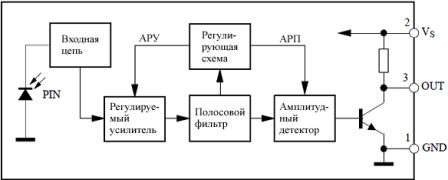
Figure 3. Block diagram of the photodetector
The RC-5 protocol will not be explained in detail here, since this ignorance will not affect the further story, and indeed the repair of the remote control. Those wishing to get acquainted with the RC-5 protocol in more detail can find its description on the Internet. This is already a topic for a separate article.
Remote control device
With all the variety of modern remote controls, all models are arranged almost the same. The main difference is most often in the appearance, in the design of the device. As mentioned in the first part of the article, the basis of a modern remote control is a specialized microcontroller. The program in the MC is recorded during the manufacturing process at the factory and cannot be changed in the future. When included in the circuit for such an MC, a minimum number of attachments is required. A diagram of a modern remote control is shown in Figure 4.

Figure 4. Scheme of a modern remote control
The basis of the whole device is a U1 chip of the SAA3010P type. Although the letters may be different, which speaks of a different manufacturer of the microcircuit. But the numbers still remain 3010.
As mentioned above, there are practically no hinged parts. First of all, it is, although it is not entirely accurate. Its purpose is to synchronize the internal generator of the microcircuit, which provides the required time characteristics of the output signal.
The KEY MATRIX is shown in the lower right corner of the diagram. Its lines are connected to pins DR0 ... DR7, and columns, respectively, to pins X0 ... X7. When you press any button, one column-row pair is closed, and a pulse sequence appears at the output of the microcircuit corresponding to the pressed button. Each button gives out its own sequence and no other! In total, it is possible to connect 8 * 8 = 64 buttons, although in practice it can be less.
The output signal in the form of voltage pulses is fed to the gate of the field-effect transistor VT1, which in turn controls the operation of the IR LED VD1. The control algorithm in this case is very simple: the transistor is open - the LED is on, the transistor is closed, - the LED is off. In this case, they say that the transistor operates in a key mode. As a result of such flashes, pulse packets are formed that correspond to the RC-5 control protocol.
The circuit is powered by two AA-type galvanic cells, the energy of which lasts for at least a year. In parallel to the batteries, there is an electrolytic capacitor C1, which, by shunting the internal resistance of the batteries, prolongs their service life and ensures the normal operation of the remote control when the batteries are a little “dead”. The LED in the pulsed mode can consume current up to 1A.
After considering the remote control scheme, it seems that we can say that there is absolutely nothing to break with such a simple device, but this is not so. It is the remote control that most often causes trouble for the owner of the TV. How to repair the remote control, what are its main "diseases", as well as how and how to cure them will be discussed in the second part of the article.
15:45 20.03.2002
Three ways to control a computer through any IR remote control This material contains mainly theoretical information on the use of infrared remotes from televisions and other household appliances to control a computer. It is not so difficult to find a real use for such a possibility. You can control the launch of programs; by moving the mouse cursor and simulate pressing its buttons; simulate keystrokes on the keyboard; manage WinAmp; shutdown and restart the computer.
Three methods will be discussed. All of them assume the presence of an IR receiver connected to the computer. The last two methods contain primitive circuits, which will not be difficult to solder on their own.
Let's start with the simplest option - work through conventional infrared adapters, which are sold in many stores for $ 15 to $ 40. They are connected via USB bus or RS-232 serial port (regular COM port). The last option for our venture looks preferable, because the reviewed software will most likely not work with USB versions adapters. They are also cheaper. In our case, we used a TEKRAM IRmate IR-210B adapter connected via a COM port. Immediately you need to warn that the programs found and described by us do not require the installation of drivers for any adapters. The programs themselves work directly with the COM port. Installed drivers will interfere with normal operation. If you use USB versions of adapters, then the situation is the opposite - drivers are needed, but, as mentioned earlier, support for devices of this kind was not listed in the settings of all programs.
The program is distributed under the terms of Shareware. In demo mode, only four remote control commands can be used. Supports various adapters, including those working through WinLirc (this will be discussed separately). AVerMedia TV-tuner remotes are supported directly. A complete list of supported devices can be found on the developer site.

The program turned out to be quite easy to use. There is support for the Russian language. Let's start the description of working with the program with the settings.

They are located in the "File" menu. Initially, you need to specify which port the adapter is connected to. For our IRMate 210 there was a remark in the program description: it works only at a port speed of 2400 bps. We obey the instructions, otherwise, all settings are quite optimal. The logic of working with this program, however, and with the others too, implies that you must first enter the source in the program - the control panel. In our example, we named it "Samsung". Then commands are added to the source, they are located under the name of the console. When adding them, the program assigns signals from the remote control to their values. To assign an action to a button on the remote control, just drag the required command into the "Triggered commands" window and specify everything you need in the "List of actions" tab. An unregistered version of the program will not allow you to create more than four actions on one diagram.
 Let's start the description of working with this program by setting it up. When you start the program for the first time, you will find yourself in the "General Config" section of the main menu. In it, you must select the type of adapter used. In our case, this is the Generic Serial IR Receiver. Next, we move to the "Hardware Setup" item.

Similarly to the previous program, right-click in an empty field and select "New Remote Control" from the menu. We named it Samsung. Next, using the right mouse button, we begin to add keys from the IR remote control ("New remote Button"). In the process of identifying the remote control buttons, a problem arose - the program seemed to have all the button codes the same. The button code is displayed on the right in the "Signature" window and is a simple set of data read from the COM port. Everything was solved simply: in the screenshot next to the port indication there is a "Setup" button. It calls the settings window, where you need to select the second tab with the name "Device Settings". In it, in the value of the "IR code length" parameter, put a larger value, for example, 32 bytes.
To assign actions to the already defined buttons on the remote control, you need to go to the third section "Actions". Add our remote and add the buttons that we defined in the previous section, only now the selection will be from the drop-down menu invoked by the right mouse button. Actions for commands are added in the right window.

By putting a check mark in the "Disable OSD" item, you will get rid of the window that will pop up on the screen when you press this button on the remote control.
Subjectively, I like uICE more than PCRemote. But it's better to try both, because they have several differences. In addition, if you are going to use unregistered versions, then uICE will completely lose its functionality after 30 days, while PCRemote will work with the aforementioned restrictions.
Working with homemade IR receivers
The above method is suitable for those who already have an IR adapter or the purchase of one does not cause any difficulties. Otherwise, the simplest IR receiver connected via a standard RS-232 port is not at all difficult to build yourself. Moreover, there are many more programs that work with homemade IR receivers. The most popular such program is WinLirc. It would be more correct to call it not a program, but an interface for working with a COM port. This interface is used by all other programs that will be described below.
 This is the interface for the devices described above. It runs under Windows 95/98 / ME / NT / 2000. It was originally created for Unix, so fans of this operating system will find everything they need at this site www.lirc.org. By itself, this program is only capable of receiving and processing signals received from the COM port from our device. In order to use the remote control to perform any actions on the computer, other programs are needed, which in turn will receive all data from WinLIRC. All the programs described above are capable of working with WinLIRC.
 Version 2.0 was released just the other day. The program is distributed on the terms of Shareware, but there is a free registration for citizens of the former USSR. The program has a wide range of possibilities: from keyboard emulation and WinAmp control to control of external devices. All these features appear only after installing the corresponding plugins. All of them are located on the author's website.
In our case, we will have to work with this program through WinLIRC. Plugins for working with conventional IR adapters, according to the author, are just being developed. Frankly, I myself did not solder this circuit, so these and further statements are better attributed to the theoretical part. Therefore, it is wiser to continue without further ado to provide a few annotated links.
The considered schemes are intended for remote control of loads via a telephone wire line, via mobile and radio communication channels, as well as control of various devices using an infrared channel.
The infrared control device consists of two units - a transmitter and a receiver with a possible range of up to seven meters. The remote control circuit is built using the PIC12F629 microcontroller, the firmware of which you can download from the green arrow just above.

The basis of the IR transmitter circuit is the PIC12F629 microcontroller for its correct operation according to the RC5 protocol, a stable carrier frequency of 36 kHz is needed, therefore, an external generator is used in the design on the radio components Q1, C1, C2.

The modulated IR signal from the transmitter is fed to the TSOP4836 receiving module and processed by the PIC12F629 in accordance with the firmware. Depending on the pressed button in the transmitter circuit, the desired channel in the receiver is triggered. The relays carry out load switching on each of the channels. To flash microcontrollers use.

For almost any radio call, it is quite easy to make a set-top box to control any household appliances. The refinement allows you to remotely turn on and off a household appliance, into the power circuit of which relay contacts are inserted
On this page, I have collected simple and repeatable schemes for remote control of a load on microcontrollers, for example, lighting or any household appliances. You can find firmware and other additional files for projects here.
The considered circuits carry out remote control of the load. Both designs have a programming function that makes it possible to turn on or off different loads at a distance by pressing the programmed button
The schematic diagram of the transmitter is shown in Figure 1. SW1 is a module of eight DIP switches. It is installed on the board and allows you to set an individual code - an eight-bit binary number. The receiver must have exactly the same code, otherwise it will not respond to commands from this transmitter. Instead of a block of DIP switches, you can unsolder ordinary wire jumpers, but, again, the x wiring must match the wiring of the jumpers on the receiving unit
The circuit is powered by a 5V power supply. The digital microassembly CD4017 is a typical counter divider by 10. The received signal from the sensor goes to the microcircuit, in accordance with the signal at the outputs Q0-Q9, a high state is set, in our circuit example, a relay is connected to the output of Q1 through a bipolar transistor T2. Almost any load can be connected to a high-voltage circuit - from an ordinary iron or microwave to a refrigerator or air conditioner

The illuminated Status LED indicates that the signal has been received and the relay has triggered. It can even use any TV remote control as a remote control. Appearance of the assembled device on the breadboard:

In this article, we'll talk about how to assemble an IR load control with your own hands. The control circuit can control various loads connected to it: light, fan, household appliances. IR control is carried out using any remote control, including television.
In the first considered scheme, a fan or a cooler is controlled by a signal from a thermistor during a specified time interval. The amateur radio design is very simple, because it is assembled on only three bipolar transistors. Such control systems can be used in a wide variety of areas where cooling with a fan is required, for example, cooling the computer's motherboard, in powerful sound amplifiers and power supplies, and similar devices that can overheat during their operation.


