It has always been difficult to get high-quality antennas - the Soviet industry practically did not produce them, so people themselves made them from improvised means. Today, the situation has not changed much - in stores you can only find lightweight aluminum Chinese crafts that do not show good results and rarely live more than a year. What to do if you like to watch TV as well good reception No? The answer is simple -With free time and a pair of skillful hands, anyone can handle this.
More recently, Russia has analog television, but now almost the entire country has switched to digital broadcasting. Its main difference is that it works in the decimeter range.
Create a homemade antenna for digital range possible at home
This was done for reasons of economy and safety - care for transmitting antenna-feeder stations is actually not required, their maintenance is minimized, and harm from contact with powerful transmitters for masters is minimal. But such stations have one serious drawback - low power. And if in a big city the signal can often be caught even for a segment copper wire reception may be difficult when away from the transmitter. If you live outside the city, in remote areas or villages, you will have to assemble your own antenna and take it outside to catch the desired signal.
Attention:signal problems can occur even in the city center. Decimeter waves are practically not muffled by other sources, but are reflected from thick reinforced concrete walls. In modern high-rise buildings there are many places where they are completely attenuated, not reaching the TV receiver.
It is also worth noting that DVB-T2 ( new standard television) offers a fairly constant but weak signal. With a noise level one and a half to two units above the norm, the TV reproduces the air quite clearly, but as soon as the noise exceeds 2 dB, the signal disappears completely. Digital television is not sensitive to electromagnetic interference- it is not knocked down by a working refrigerator or microwave. But if there is a mismatch anywhere in the system, then the picture stops or falls apart. qualitysolve this problem, but in some cases, it will have to be taken out onto the street or onto the roof.
Basic requirements for antennas
The television standards in force in the USSR do not fit modern realities - the protective and directional coefficients today have practically no effect on signals. The air in the cities is clogged and contains a lot of dirt, so you should not pay attention to these coefficients. You are guaranteed to receive interference on any antenna, so you do not need to achieve a reduction in DRR AND NPV. It is better to improve the gain of the antenna so that it receives a large range of air and selects the desired stream, rather than focusing on a specific signal. The processor of the set-top box or TV itself will isolate the necessary signals and create a normal picture.
 Classic Polish antenna with amplifier
 So, Experienced engineers recommend building band antennas. They must be correctly timed by taking signals the classic way, and not due to engineering "optimizations" and traps. Perfect option— the device fully complies with theoretical calculations and geometry. Also, the constructed antenna must be consistent with the cable at operating ranges without the use of matching devices. In this case, it is best to create a frequency response smooth and even, since phase distortions appear when the amplitude-frequency characteristic fails or jumps.
Attention: analog antennas with ferrite USS, which provide full-fledged reception of the old signal, practically do not work with DVB. It is necessary to build a “digital” antenna.
In the article we will analyze modern types antennas working with new digital broadcasting.
Antenna types
What do-it-yourself digital TV antennas can be collected at home? There are three most common options:
- All-wave, or as radio amateurs call it, is frequency independent. It assembles very quickly, does not require high knowledge or specialized tools. Well suited for the private sector, villages, summer cottages - where the air is not littered with garbage, but not far from the transmitter.
- log-periodic range. It has a simple design, well receives a signal at a close and medium distance from the transmitter. It can be used as a remote if the transmitter is located far away, or as a home wall antenna.
- Z-antenna and its variations. Many radio amateurs are familiar with meter-long "zashkas" - they are quite large and require a lot of effort to assemble. But in the decimeter range, they are quite compact and do their job well.
The nuances of construction
If you want to build a quality antenna, you must master the art of soldering. You can not twist the contacts and guides - during operation they are oxidized, the signal is lost, the picture quality deteriorates. Therefore, all connections are soldered.
 Such connections are not allowed - be sure to solder them
 You also need to deal with zero-potential points where currents occur even when there is no voltage. Experts recommend making them from a single piece of metal, without using welding at all. Even high-quality welded pieces can make noise at the boundary values, while a solid strip will “pull out” the signal.
Also when creating homemade antenna for digital TV you need to deal with soldering cables. Today, copper is practically not used for braiding, since it is expensive and quickly oxidizes. Modern braid is made of steel, which is not afraid of corrosion, but it is very poorly soldered. It must not be overheated or squeezed. Use 36-40 watt soldering irons, flux and light solder to connect. Dip the winding well in the flux and apply solder - it is perfectly taken with this method of application.
All Wave Antenna
The all-wave antenna has a fairly simple design. It consists of triangles, copper wire and wooden slats. You can study the design in more detail in the picture - it does not represent something supernatural.
The thickness of the wire can be any, the distance between adjacent wires is 25-30 mm, the distance between the plates is no more than 10 mm. The design can be improved by abandoning the plates and using textolite. It needs to be given the appropriate shape or just remove the copper foil in the shape of a triangle.
The remaining proportions are standard - the height of the device must match the width, the plates diverge at a right angle. Zero potential is on the extreme line home tv antenna , just at the intersection of the cable with the vertical guide. To avoid quality losses, the cable must be pulled to it with a tie - this is enough for coordination. Such an antenna, hung out on the street or directed at a window, receives virtually the entire frequency range, but has a small dip, so you need to set the correct angle when fixing the antenna.
By the way, this design can be upgraded with ordinary aluminum cans from beer and cola. The principle of its operation is as follows: with an increase in the span of the shoulders, the working band expands, although the rest of the indicators remain within the original limits. The Nadenenko dipole, often used in military developments, works on the same principle. Aluminum cans fit perfectly in shape and size, creating vibrator arms in the decimeter range.
 Double Can Antenna for TV
 You can create a simple canned antenna by simply soldering two cans to a cable. This do-it-yourself indoor TV antenna suitable for viewing channels at a small to medium distance from transmitters. Nothing needs to be coordinated in this scheme, especially if the cable length is less than 2 meters.
You can complicate the design by assembling a full-fledged lattice from eight cans and using an amplifier from an ordinary Polish antenna. This design is great for hanging outdoors in areas remote from the transmitter. To enhance the signal, a metal mesh can be placed behind the structure.
Z antenna
There are complex Z-antenna designs with multiple loops, but in most cases they are not needed. You can easily assemble a structure from ordinary copper wire 3 mm thick. If you don’t have one, then just buy a single-core copper wire 3 mm long, 120 mm long - this will be enough for you to work. This design consists of two segments. We bend the wire according to the following scheme:
- The starting section is 14 centimeters long. Its edge is bent into a loop to connect with the last one (loop 1 cm, total length of the first piece - 13 cm).
- The second piece is bent at 90 degrees (it is better to bend with pliers to keep the angles). Its length is 14 cm.
- The third piece is bent at 90 degrees parallel to the first, length 14 cm.
- The fourth and fifth pieces are 13 cm each, the bend does not reach the loop by 2 cm.
- The sixth and seventh pieces are 14 cm each, bent at 90 degrees.
- Eighth - returns to the loop, length 14.1 cm goes to a new loop.
Next, you need to clean the two loops well and solder them. The opposite corner is also cleared. The cable contacts are soldered to them - to one central, to the second - a braid. There is no difference to which contact to solder.. It is advisable to insulate the soldered places, for this you can use sealants or hot melt adhesive. The ends of the cable are soldered to the plug and also insulated with cambric.
 You can assemble such an antenna in half an hour
 To avoid displacement of the segments, the edges can be reinforced. To do this, take an ordinary plastic cap from a five-liter bottle, cut 4 slots in it so that the wire sinks to the base. Cut the fifth hole for the cable. Then put the antenna into the cover (after checking the quality and reliability of the soldering), and fill it with hot glue. The resulting design will be almost eternal - it is able to take steady signal up to 10 km from the source.
So you already know what can be used instead of a TV antenna. In fact, the designs are much larger than those that we have described, but even these will be enough for you. If you live far from the signal source, then you will need amplifying antennas - you can get by with the classic “polka” with gain. Well, if everything is bad with the ether, then use satellites.
Good afternoon, V.Yu.
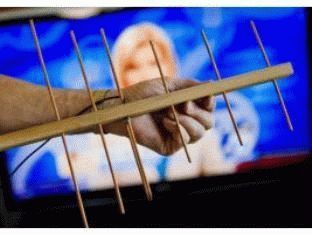
The visitor in the last posts with experience in FM radio antennas is me. The antenna turned out to be easy to manufacture and I decided to repeat it for FM reception and compare it with those previously made, by ear, according to instruments, ease of use. The goal was to obtain a signal with a minimum of interference for high-quality sound radio in stereo. Made two antennas. The first of the wire is 3 mm thick. The second is made of metal. From the metal-layer, it turned out to be slightly better in terms of the level of received signals. Sounds less low frequencies, more highs and distinctness of each instrument in the orchestra.
Measurement method - there is a receiver with a signal level indicator in decibels. We number the stations of the FM band and look at the level of the received signal from the station in dB, then we summarize all the values. We get numerical value antennas according to the received signal level parameter. All antennas were placed under the same conditions in direction. Wire on a window 303 cm long in the form of a rectangle with a gap along larger side in 2 cm (51 cm x 102 cm) - has a value of 491 dB, a directional loop phased loop antenna from a wire - 459 dB, the same from a metal-plastic - 485 dB. As can be seen from the presented values, the metal-plastic antenna is comparable to a full-size frame equal to the length waves in the middle of the FM band.
Now for the manufacturing technology. it is somewhat different from yours and is made without soldering. The base is a rail (30 x 6 x 3 cm). Remained from the repair (2 pcs). Wire antenna - circumference 75 cm (four-wave mid-FM range). Two circles of the same length. We take a light self-tapping screw (not dark - it has a cone head) with a flat head for a Phillips screwdriver. We make a hole in the rail with a drill or in another way so that the wire enters the hole with little resistance. You can slightly bend the ends of the wire for this purpose. We put the two ends of the loop into the hole of the rail and do not connect them together (leave 5 mm between the ends of the loop). We do the same with the second loop at the other end of the rail. The distance from the end of the rail is 1 cm. We screw the screws on top of the rail so that the end of the screw enters the loop wire at the end. This ensures the contact of the coax with the frame. Under the screws we wind the central core of the coax and the braid with different sides framework. For example, the central core is on the left, and the braid is on the right in the direction from the beginning of the rail to its end. Between the frames we lay the coaxial and fasten it to the screws (we wind it under the screw head). The second loop is also fastened and the ends of the coax are fastened under the screws for fastening the second loop. The descent in the form of a coaxial - I got a length of 7.5 meters, we fasten it under the screws of one of the frames (the central core is on the left, and the braid is on the right. self-tapping screws - 2 cm We connect the other end of the coax to the receiver through the connector you need.That's it - the antenna is ready.
Metal-plastic differs in manufacturability. Pipe 20 mm, also after repair. It bent into a ring without problems. Loop length 75 - 1.5 cm (as recommended in the article) = 73.5 cm. Fastening the loop to the rail is also a self-tapping screw, but bigger size so that it passes through the metal-layer and is well fixed to the tree, by 10-15 mm. There is a distance of 1 cm between the ends of one loop. The screws are still at a distance of 0.5 cm from the end of the loop. We get a distance of 2 cm between the screws of one loop. We lay a piece of metal-plastic between the loops and fasten it with screws to the rail, so that coax can be inserted inside. We connect the coaxial in the same way as in the first case to the ends of the loop, the central core and the braid. We ground the tube between the loops of the antenna (we connect it with a braid). We put a piece of coax into the pipe between the loops, connect the c.zh. and braid. We also connect the reduction coaxial with the screws of one of the loops (c.zh. and braid). We pre-clean the ends of the loops from vinyl to aluminum so that the screw head presses the wires to the aluminum and at the same time fastens the loop to the wooden rail.
With all respect, Andrew
Television is in every home today. With the development of technology, the quality of television signals and the methods of their transmission are changing. And if yesterday the antediluvian was used analogue broadcasting, today exclusively digital is being persistently discussed.
On the territory of Russia, the state-owned company RTRS is engaged in television and radio broadcasting. Since 2012, the government decree has been recognized single standard digital terrestrial television DVB-T2, multiplex standard digital broadcasting. RTRS, as the only broadcast operator, offers two multiplex packages at once (RTRS-1 and RTRS-2) to free viewing. All you need is a modern receiver-antenna, one of the options for which we propose to do with your own hands today.
This homemade product is based on the development of engineer Kharchenko K.P., who proposed similar antennas for the decimeter range (DCV), popular in the 90s of the last century. This is a similarity of aperture antennas, based on which the feed is in the form of a zigzag shape. The signal is accumulated by a flat reflector, which is at least 20% larger than the vibrator.
TV signal transmitted in waves from horizontal polarization. In a simplified form, such an antenna consists of two horizontal loop vibrator, interconnected in parallel, but disconnected at the connection point of the feeder (cable). dimensions are given on the basis of Kharchenko's article “Antenna of the DTSV range”, and are calculated according to the proposed formulas. According to this technology, such antennas can be calculated even for weak signal about 500 MHz.


What you need to assemble the antenna
Materials:- Barbecue grill;
- Aerosol paint for cars;
- Solvent or acetone;
- A set of drills for a conventional drill;
- Coaxial TV cable - no more than 10 m;
- Half a meter of PVC pipes XV, diameter - 20 mm;
- Metal dowels for drywall;
- Copper wire for the antenna vibrator, core diameter - 2-3.5 mm;
- Two thin metal plates.
- Soldering iron powerful 100 W;
- Screwdriver with nozzles;
- hot glue gun;
- Pliers, hammer, wire cutters;
- Paint knife, tape measure, pencil.

Let's start making an antenna
Making a frame vibrator
We measure the required length copper wire with a margin of about 1 cm. You can also use a copper or aluminum tube with a diameter of up to 12 mm.

We clean the copper core from insulation, and level it with a hammer on a hard surface. Mark the middle and make a 90 degree bend. The most accurate way to do this is in a vise, slightly pressing the copper core and leveling it with a hammer.


According to our calculations, the sides of the squares will be 125 mm. We mark them with a tape measure, and make bends.


From one end we bite off a small fragment with side cutters, making the tip pointed at 45o. After bending the second square, we carry out the same procedure, biting off the final end of the core. Squares for this can be slightly straightened.


On the middle bends of the squares, we achieve a distance of 10-12 mm. At the ends we make shallow cuts with a needle file. This will help us pull both free ends together and secure them with thin copper wire.


Using liquid rosin or flux, we tin the middle bends with a soldering iron. This must be done on all sides of the copper core of the vibrator.


We clean the coaxial cable by 4-5 cm. Braid or outer conductor twist into a single wire, wrap it around one of the bends. We solder it to the copper core with a soldering iron.


We clean the insulation of the inner conductor, and also wrap it around the next bend of the frame. You need to solder it carefully while holding the insulation with pliers, because it can simply shift from the center due to temperature. We first heat the frame in the soldering zone, and only then the conductor itself.


We fix the eyeliner coaxial cable with a nylon screed, degrease with a solvent and isolate the soldering points with hot glue using a gun. You can correct the defects of the resulting cast form of glue with a hairdryer.


Cooking reflector
We use an inexpensive barbecue net as a reflector or reflective screen. This is a good material, since even steel samples of such products are covered with a corrosion-resistant anodized coating, not to mention stainless steel. A heat exchanger is also suitable modern refrigerator or a drying rack for dishes. The main thing is that this element, if possible, does not rust in the air.The reflector grid should be larger than the vibrator frame, but need not be symmetrical. We cut off the handles from the lattice, they will be superfluous in our design.


We place the antenna frame in the middle of the reflector, and mark the places of its fastening. For fastening, you can use two plates of any metal. We bend them along the grid, and drill holes with a diameter of 5 mm.


Assembling the antenna
We cut off two pieces of PVC pipes 75 mm long, and screw them into the end of each with a self-tapping screw, cutting off the protruding parts. At drywall dowels, we break off the pointed tips, and screw them into the opposite end of the tubes.


We fasten both PVC racks to the slats on the reflector with self-tapping screws. We tin the frame at the ends that fit the racks for better heat transfer.


On the racks we mark the height of 68 mm, and put at risk. We heat the ends of the frame with a soldering iron, and solder them into the racks to the desired marks.
Learn those who want to tune the antenna to television: digital gizmos are not created by nature. There are analog signals in the Universe, the power varies according to the quantum states of electrons. The transitions are so small that they seem continuous to a person. The signal can be represented by a certain number multiplied by elementary energy. We want to make it clear: nature digital signal in the understanding of mankind is deprived, a digital antenna is not independently constructed. It is possible to make an antenna for receiving analog signal carrying digital information.
Antennas for receiving a digital signal
Today it is exclusively digital television. However! Multiplexes, where programs are stamped with frames, contain radio broadcasts. We would like to clarify: in the current state of affairs, radio broadcasting has gone up, capturing the frequencies of the FM band, television has been completely replaced in the UHF. Explained by features modern life. The driver wants to listen to the radio, watch TV on the road. seen long antennas walkie-talkies? 34 MHz. Compare: USSR Channel I broadcast 50 MHz. Should everyone on the roof have an antenna two meters long to watch the center channel?
It's just ridiculous. In contrast to sticks, FM-UHF antennas are relatively small. Easily fit on the roof. Relieving the suffering of moviegoers, the channels carry one frequency. The picture is broken up by frames, it turns out that a lot of programs are available with a single antenna setting. Comfortable. Tons of benefits technical solution we will see from the phenomenon called today the digital multiplex. It becomes possible to accurately aim the antenna at the receiving frequency (which is a trivial UHF channel) in order to watch broadcasts, listen to the radio.
To solve the problem, a device that appears to be a "home-made digital antenna" is constructed by some. The antenna is ordinary, - we will add if we are interested in the type - linear. The design was chosen due to its small dimensions. Highlighted in digital transmission one problem…
Television is used to using horizontal polarization. fate befell digital multiplex. It turns out that the signal is caught then amazingly when the antenna line is perpendicular to the beam of the incoming signal. If we break the rule, power starts to be lost, reception worsens.
Reception of a digital signal by an antenna
Those wishing to receive a digital signal must understand the type of polarization electromagnetic radiation. discard satellite television broadcasting in frames, the polarization, as Vladimir Volfovich says, is unequivocally horizontal. It is customary to catch the type of signal by television on a half-wave vibrator, there are two types of signal:
- Symmetric.
- Asymmetrical.
Let's explain. The first is formed by identical arms equal to a quarter of the wavelength. In total, half the wavelength is obtained. The signal core of the cable is connected to one shoulder, the shield is connected to the opposite. Shoulders in a row form a line, separated by a gap of 20 mm. To match, equalize the resistance of the antenna and cable, take the trouble to symmetrical. The first condition is ideally fulfilled, the second at UHF frequencies with decreasing wavelength plays a smaller value.

To make a digital antenna on your own, it is enough to equip the mast with a carrier plate, attach horizontally symmetrically two wire arms 3 mm thick, each quarter-wave long.
The resulting device is soldered onto a coaxial with a wave impedance of 75 ohms, as indicated above, the length of the drop cable is taken as low as possible, each meter eats up part of the useful power with losses. Only the length to the first amplifying stage plays a role. Supplying the roof with food by placing a purchased block desired frequency, a bay in the corner, rolled up behind the TV, we make it impossible to spoil the reception. The effect of overamplification sometimes introduces unpleasant visual effects, the most famous is considered ghosting.
Another negative is possible. First, you should try the antenna without an amplifier. Reception will not be distorted by excess power. If unpleasant side effects are observed, it is worth trying to fight for quality improvement. It is important to direct the antenna more precisely. In the city, due to the multipath effect, in the village, due to the deviation of the direction of the wave from a straight line, the beam exit point is not where the compass points (according to the map). You should slightly move the antenna, setting the right direction, finding the best position.
Antenna reception
The half-wave vibrator of the design described above forms two main lobes in the radiation pattern. Spread 180 degrees. The radiation pattern is symmetrical in the horizontal plane. Therefore, we will improve the performance by installing a screen. The obvious solution, we rarely see for a simple reason: the antenna must catch wide range difficult to find the correct distance. For a half-wave vibrator, the screen will not be a piece of conductive material - a pair of pieces of wire from which the arms are made. The distance between them is not so important, it should not be large. It is quite enough 5 centimeters up and down from the plane where the shoulders are. The length of the screen exceeds the span of both, electrically located on the cable sheath.
The distance between the screen and the half-wave vibrator becomes important. Difficulty with the correct answer, what abyss separates the details, for zigzag loop antennas the value is 0.175 of the wavelength of the signal. We believe that amateurs have the right to try to experimentally select desired distance, professionals have a chance to simulate the MMANA system. The former will get an acceptable result faster, the latter will be able to predict the final alignment of an arbitrary wavelength, which is preferable. Antenna modeling is not within the scope of the authors' interests, enthusiastic people are able to lay out finished file, flavoring the comments with the fruit of technical thought. We believe the alignment will reduce the amount of interference.

Unbalanced digital antenna
As for the asymmetrical half-wave vibrator, it represents one shoulder. The second is replaced by "earth" (an infinite plane of zero potential), in practice there is simply nothing in this place. The manufacture of a half-wave asymmetric vibrator has been repeatedly shown by forums, the VashTechnik portal, and the network. Usually the antenna serves as a room addition digital receiver who is afraid of catching on his own. To make the adjustment, the wavelength of the channel is calculated, divided by four. The cable screen is cleaned along the segment, the internal insulation is preserved - it will not interfere with reception.
An F-connector is screwed onto the end bent by 90 degrees, which is inserted into the receiver, TV socket (contain the receiving part of the terrestrial digital television desired chip generation). Almost all modern plasma panels right inside. Tuning will take time, the channel frequency is known. You need to find out the number - visit the site http://rtrs.rf, look at the region, call desired phone. E-mail inquiries are accepted. Of course, if the region is deprived of digital television, no information can be found.
The given site is the official resource of the state unitary enterprise, which is entrusted with the task of digitizing the space of the Russian Federation. Ask, is a log-periodic digital antenna made by yourself? The answer is no need. The log-periodic antenna covers a large range, if you want to watch three Moscow multiplexes, take it. Rejecting fear, use a wave channel type antenna, which differs from a log-periodic one in slightly worse range characteristics, simpler design. The manufacturing technique was discussed, the provinces did not make much sense to waste time.
Readers understand: the device of a digital antenna is identical to the usual one. Polarization is linear horizontal, the frequency is determined by the channel. The principle of operation of a digital antenna is similar. transformation electromagnetic wave into the current inside the conductor. A feature of digital antennas is that they are precisely tuned to one frequency. The design is simple and efficient. Promising quality viewing (no visual or audio interference). Naturally, the TV, set-top box must decode the signal.
It remains to say goodbye to the readers. Today the amateur radio industry is a thing of the past, who will predict the awaiting humanity of tomorrow...
So, imagine this situation: in the evening you decided to watch your favorite TV program, and suddenly the TV stopped showing. Or another case: you arrived at the dacha, already prepared for the rest, and again the same situation - not a single channel works. How to proceed in such a case? The answer is simple - you need to make an antenna for the TV with your own hands, because most likely the cause of the breakdown is in this device. Next, we will look at the most simple options creations that require a minimum of improvised means and time.
Idea #1 - Beer cans in action!
This version of homemade television antenna is the easiest and fastest to manufacture. Maximum amount channels, which will be provided at your disposal - 7, but this figure may vary slightly depending on the region.
To make a beer can TV antenna, you will need the following materials:
- 2 small self-tapping screws, also called "bugs";
- 2 prepared beer cans (empty, washed and dried)
- from 3 to 5 meters television cable(can be taken from a failed device);
- soldering iron and tin (for better fixation contacts), availability is optional;
- screwdriver;
- wooden trempel;
- tape or tape.
Finding all the materials in the house will not be a problem, so having prepared them, we immediately get down to business.
In order to make a homemade antenna from cans, you need to perform the following steps:
- We prepare the cable. First, at a distance of 10 cm from the edge, you need to make an incision and remove part of the top layer of insulation. Having opened access to the screen, we turn it into one coil. After that, we cut off the middle insulating layer, exposing the thin copper core of the cable. As for the second end of the conductor, there should be a regular plug.
- Preparing banks. With containers that will act as a signal receiver, there will also be no difficulties. First you need to choose the optimal dimensions of beer cans. It is better to use liter ones, but if there are none, they will cope well with the task of containers with a volume of 0.5 and 0.75 liters.
- Let's make contacts. At this stage, the twisted screen of the cable is fixed to one bank, and the copper core itself to another. Fixation is carried out with bedbugs using a screwdriver. In order to make the picture quality on the TV screen higher (signal transmission quality), it is recommended to fix the wire not only with bedbugs, but also with a soldering iron (grab a little). The result should look like this:

- We collect a homemade antenna for the TV. The signal receiver is ready, now we are making a supporting structure, which we have a trempel. Using electrical tape, we fix the containers to the trempel (as shown in the photo). We draw your attention to the fact that the banks must be strictly on the same straight line, otherwise the homemade product will not work as we would like.

- Setting up a TV antenna. Now you need to experiment with the optimal distance between the banks, as well as the place for hanging the device, so that the homemade product catches a lot of channels. We turn on the TV and determine exactly how the receivers should be located and where is the most suitable place to work. This is where the creation technology ends.

As you can see, the whole process is quite simple and does not present anything complicated. Optimal Distance is 75 mm between the ends of the cans, and the best place installations - near the window. In individual cases, the distance between the banks can be made more or less.
Idea number 2 - Use wire
One more no less a good option, which is advisable to use in the village - a home-made antenna made of copper wire with an amplifier.
All you need to make is:
- amplifier (suitable from an old device);
- two pieces of wire 180 cm each;
- a piece of metal (or wooden) plate 15 * 15 cm;
- electric drill with a set of drills (or a welding machine);
- small bolts;
- hammer;
- iron pipe;
- television cable of suitable length.
So, in order to make a copper wire antenna for a TV yourself, you need to follow these steps:

Pay attention - in the photo examples, both the amplifier, and the reflector, and the wire are covered with paint. Painting protects the structure from corrosion and other adverse factors, significantly extending the life of a homemade TV antenna.
Idea #3 - Home HDTV device
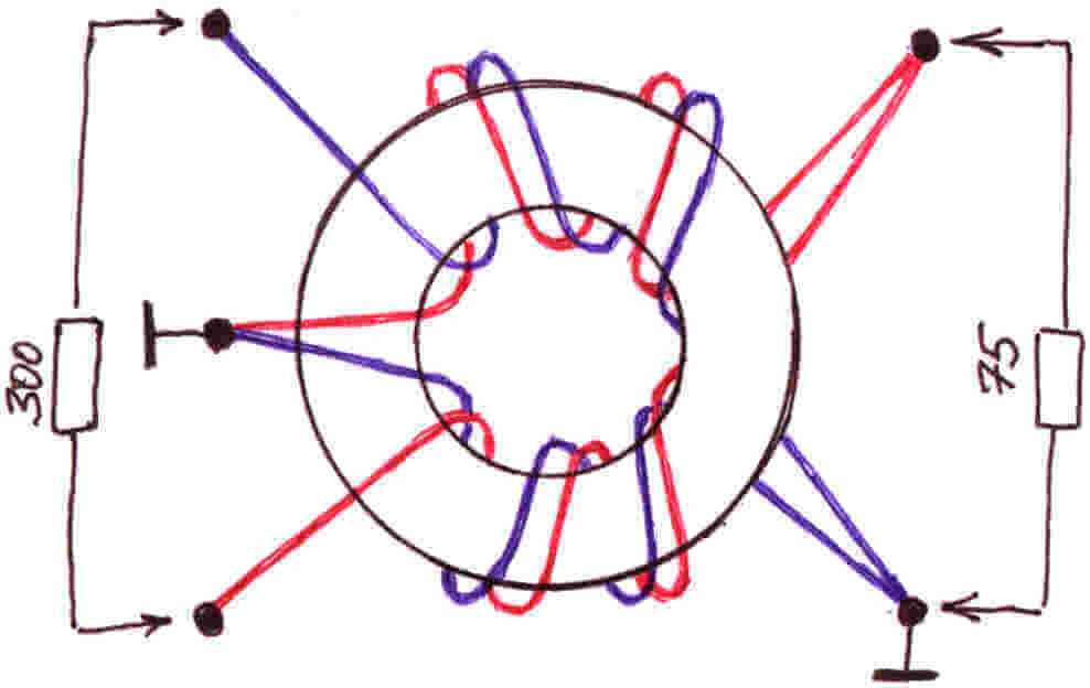
If the first 2 options worked at a frequency of no more than 270 MHz, then next way production will allow you to enjoy a better picture, because. The signal range can reach up to 490MHz. The only detail that is unlikely to be found among household trifles is a matching transformer from 300 to 75 ohms. You will need to buy it in advance if you decide to make a TV antenna yourself as an experiment and improvement of your skills. Although there is an instruction for making a homemade transformer, you can find and use it.

From the materials you will need:
- Scotch
- Cardboard
- Stationery knife
- Foil
- stapler
- Scissors
- Marker
- Roulette
Having prepared all this school set, let's get down to business!
First you need to sketch (or print on a computer) this diagram:


Now, according to the scheme, we cut out all the spare parts, including the necessary pieces of foil:


After that, you need to make a reflector with dimensions of 35 * 32.5 cm (height and width). Cover one side with foil.


In the middle we cut out two identical rectangles, which are necessary in order to fully assemble the signal catcher of a homemade antenna for the TV. The rectangle should be 3.5 cm long, its purpose is to maintain the distance between the reflector and auxiliary parts.


We glue the spare parts onto the rectangle, and when the cardboard home-made hardens, we drill holes for the TV cable.


We connect the transformer and insert the cable into the plug. A more powerful TV antenna is ready to use! It should also be noted here that this option homemade products are suitable only for indoor use, tk. paper deteriorates quickly on the street.
Another option powerful device made at home:
Idea number 4 - Apartment option
There is another way to do powerful antenna for a TV from improvised means, which is suitable for both street and apartment use.
To make the device, you will need the following materials and tools:
- 4-meter wire made of copper, with a cross section of 4 mm.kv;
- a board of arbitrary thickness, 55 cm long and 7 cm wide;
- wood screws;
- ruler or tape measure;
- simple pencil;
- screwdriver;
- soldering iron;
- plug.
So, first, according to the drawing, we drill holes in the board: 
Then we transfer the drawing data to the board and drill in the appropriate attachment points. 
Next, the copper wire must be cut into 8 pieces of 37.5 cm each. 
In the middle of each of the 37.5 cm pieces, insulation must be removed (as shown in the picture). 
We cut off 2 more copper pieces of wire 22 cm long and conditionally divide them into 3 equal parts, while at the inflection points, again, we remove the insulation. 
We bend the prepared wire in bare places. We draw your attention to the fact that for those segments that are bent in half, the distance between the ends must be made 7.5 cm ( optimal value to receive a signal from a homemade television antenna). 
Next, we attach a plug to the finished homemade product, and we already connect a television cable to it. 
 This completes the manufacturing process. We choose a suitable place and install the device.
Here we have provided the most simple instructions. We hope that now you know how to make a home TV antenna with your own hands! We draw your attention to the fact that today on the Internet you can find many other options in which the inventors do without cans and wire. Of the other improvised means, copper tubes, aluminum disks and electrodes are often used. The advantage of the options we have listed is that you can quickly make such antennas for a TV with your own hands without spending the whole evening on it.
Related content:
Visual video instruction on creating a simple antenna from cans
Assembling a digital antenna from a TV cable and a cardboard box
HDTV antenna from improvised means
Like( 0 ) I do not like( 0 )